
Aerodynamic Optimization Design System for Turbomachinery Based on Parallelized 3D Viscous Numerical Analysis
Zhirong Lina; Bo Chena; Xin Yuana[email protected] a Key laboratory for Thermal Science and Power Engineering of Ministry of Education, Tsinghua University, Beijing 100084, China
Publisher Summary
The optimization system includes three sub-systems: parametric modeling, evaluation system, and optimization strategies. In aerospace and power-generation industries, engineers are challenged to design the highest quality systems while reducing the cost and the duration of the design cycle to achieve reactivity to the market demands and business changes. In optimization course, one problem is how to choose the design variables and reduce their number while maintaining the freedom and quality of the blade representation. The most natural way to achieve parallelization for numerical simulation is by demined composition. A suitable overlapping width of the sub-grid for domain decomposition is a key point for the present method of parallelization. The code was already parallelized by demined composition technique and running on 8 CPUs for parallel computation. An optimization design system has been used for blade design optimization, which includes three modules: parametric modeling, evaluation system, and optimization strategy. The present aerodynamic-optimization design system can be an efficient and robust design tool to achieve good aerodynamic blade design optimization in a reasonable time. This optimization system can become an efficient and robust design tool to achieve better blade performance in the near future for manufactory.
This paper has developed an aerodynamic optimization design system for blade design optimization based on a parallel computation platform. The optimization system includes three sub-systems: parametric modeling, evaluation system and optimization strategies. In parametric modeling sub-system. Non-Uniform Rational B-Splines (NURBS) technique is successfully applied. In evaluation system, an in-house parallelized CFD code and an commercial code NUMECA line/turbo are both adopted. The optimization strategies sub-system is provided by a. commercial software named iSIGHT. The iSIGHT software is also the integration platform of the three sub-systems mentioned above. To reduce the time cost by optimization process, a parallel computation platform including hardware and software was used in this paper. Two kinds of parallel mode can be applied during the optimizing process, one is using parallelized CFD code, another is using parallelized optimization strategy. Both of them can obtain good parallel speed-up coefficient. Finally, three test cases were optimized to improve the aerodynamic efficiency by using the present system. High efficiency and performance were confirmed by comparing the analytic results with those of the previous designs.
1 INTRODUCTION
In aerospace and power generation industries, engineers are challenged to design the highest quality systems while reducing the cost and the duration of the design cycle in order to achieve reactivity to the market demands and business changes.
Turbomachinery blade has complex design problems[1]. A considerable amount of research has been conducted on blade design for turbomachinery. 2D/3D blade-to-blade inverse methods employing specified flow quantities have been commonly used in the past few decades [2,4]. But inverse design is lack of direct control on parameters that indicate the improvement, and the specification of the aerodynamic duty in terms of local variables to achieve global aerodynamic optimum is not clear and needs more deliberation. In the meantime, Owing to the sophistication of internal flows in turbomachinery, many flow-features are fully 3D and can not be predicted by quasi-3D approach[5]. With the development of the in-house 3D Navier-Stokes solver, full 3D blade design using optimization techniques is becoming desirable and practical.
In optimization course, one problem is how to choose the design variables and reduce their number while maintaining the freedom and quality of the blade representation. The design variables can be derived from the geometric parameterization of blade curves and surfaces. Bezier and B-Spline curves of third- or fourth-order have been chosen for 2D blade profile parameterization which ensured good continuity of the blade surface, and the parameters defining the geometry have intuitive meanings that facilitate imposing constraints on their variance and allow restricting the design space[6,7].
Another problem is optimization strategy. Because many turbomachinery design optimization are multimodal and discontinuous problems, the use of gradient based numerical optimization algorithms perform inefficiently and drop into local minimum prematurely. Hence, the exploratory algorithms such as Genetic Algorithms (GA), Adaptive Simulated Annealing (ASA) are required for global exploration[8].
2 AERODYNAMIC OPTIMIZATION PLATFORM
The optimization platform constructed in this paper can be divided into three sub-systems: Parametric Modeling, Evaluation System and Optimization Strategy. The detailed information about these sub-systems will be described in the following subsections.
2.1 Parametric Modeling Based on NURBS Technique
The geometric representation of curves in 2D space, or surfaces in 3D space, is an important part of any shape optimization procedure. Researchers always want to represent desired shape with the least possible number of parameters for a given accuracy. Turbine blades are usually highly cambered and have round leading and trailing edges, whereas compressor blades are usually thin, low cambered and have a round leading edge and a sharp trailing edge, sometimes also have a round trailing edge. Therefore, the geometric representation of such blades with only one type of functions is quite a challenge[9],
In past decades, Bezier curves were widely used in representing airfoil, probably because of their case of implementation. However, they have two limitations, first they are global in nature, i.e. when a control point is moved the entire blade shape is modified, which results in less control over the local blade profile; second they cannot represent conies (e.g. leading and trailing edge of circular arc profile) exactly. To overcome the global nature of the Bezier polynomials, B-splines use the concept of control points introduced by Bezier, but with more complex interpolation functions that can capture local characteristics such that the displacement of a control point introduces a local modification of the curve near that point. However, B-splines still cannot represent conies exactly so that e.g. leading and trailing edge cannot be described exactly. To alleviate the shortcomings of Bezier curves and B-splines, i.e. to allow for local control of the curve and represent conies exactly, the NURBS technique can be introduced to represent the blade curves.
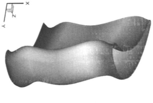
NURBS is becoming an industry standard tool for representation and design of geometry. The reasons are[10]: represent exactly conies, e.g. circles, and provide flexibility to design a large variety of shapes; be evaluated reasonably fast by numerically stable and accurate algorithms; be invariant under affine as well as perspective; be generalizations of B-splines and Bezier curves and surfaces. For turbine blade parametric modeling, there are three key points for parametric modeling process[11]: Bigger design space for all possibilities of surface transformation; Less design variables for accelerating optimization; More accurate and smooth for evaluation. Figures 1, 2 and 3 shows NURBS curve to control 2D blade profiles for turbine, compressor and fan respectively. Considering these pictures, we can say that NURBS curves are able to represent various blade profiles of turbomachinery. To form a complete 3D blade shape, 2D blade profiles must be stacked by specific stacking line. Where Figure 1 shows the stacking line represented by NURBS curve. By using this kind of stacking line, the characteristic of blade bend/lean/sweeping/torsion can be achieved. For example, supposing the meaning of x-coordinate in Figure 4 is torsion angle of blade profile, then the curve in Figure 4 can control the torsion characteristic of blade shape. By integrating 2D blade profiles and stacking lines based on NURBS technique. the complete blade can be shaped as Figure 5 shows.


2.2 Evaluation System
A 3D viscous flow analysis code proposed by one of authors, which solves the Reynolds-Averaged Navier-Stokes equations and the low-Reynolds-number q-ω two-equation turbulence model, is used to predict the effect of full 3D viscous flow through turbomaehinery. The code combines LU-SGS-GE implicit scheme and modified fourth-order MUSCL TVD scheme[12]. On the other hand, the commercial CFD software, for instance NUMECA FINE/Turbo, can also be used to evaluating the viscous flow fields.
3 PARALLEL COMPUTATION PLATFORM
The parallel computation platform consists of both software and hardware. In this paper, two kinds of network data transformation software platform are used, MPI and Windows Socket. A High Performance Computer Cluster (HPCC) were used in this paper to accomplish the heavy computation task during optimization process. The HPCC consists of 32 nodes, and each node was made up of two AMD Opteron 246 CPUs and 2 gigabytes memory. These nodes were connected through 1 gigabit/s fast ethernet.
3.1 Parallelization based on domain decomposition
The most natural way to achieve parallelization for numerical simulation is by domain decomposition. This is relatively easy for explicit schemes because the explicit schemes are defined pointwisely and are inherently parallel. In order to achieve parallelization using implicit scheme, a special interface conditions called time-lagging interface conditions with overlapping sub-grid was introduced. In previous study, the numerical results show that sometimes the grid overlapping technique will influence the numerical convergence speed and accuracy [13]. But during doing the numerical simulation of steady and unsteady cases for some turbine blade flow using overlapping multi-block grids and time-lagging interface conditions, we have found it hardly influence the convergence speed and the accuracy of the numerical results with the present LU-SGS-GE implicit scheme and higher-order, high resolution MUSCL TVD scheme[12]. A suitable overlapping width of the sub-grid for domain decomposition is a key point for the present method of parallelization. Here overlapping width is defined in terms of the number of grid points in the overlap. Figure 6 shows the decomposition scheme of blade computation domain. Figure 7 compares linear speed-up, real speed-up and idea speed-up coefficient.


3.2 Parallelization based on distributed optimization strategy
When using some of the optimization strategy, perform the different design attempts simultaneously can really accelerate the optimization course. Figure 8 shows the diagram of parallelized optimization strategy.

4 OPTIMIZATION CASES AND DISCUSSION
In this section, three test cases of optimization design system are performed. Case I and II are about a single row of turbine blade, case III is about a turbine stage. In these cases, the objective function is the total sum of the circumferential mass flow averaged loss at different radial heights at the exit plane of the cascade. The main information of them is listed in Table 1.
Table 1
Brief summary of optimization cases
| Mesh points | CPUs | Improvement | Elapsed time | |
| case I | 158,025 | 8 | 0.85% | 250 Hours |
| case II | 134,113 | 12 | 0.56% | 200 Hours |
| case III | 423,108 | 2 | 0.53% | 128 Hours |

4.1 Optimization of turbine blade based on parallelized CFD code
In this case, a single row of turbine blade was considered to be optimized. The geometry modeling techniques used in this case included NURBS blade profile and bend/lean stacking line. In more detail, the number of design parameters for 2D blade profile is 16, and the number of design parameters for bend/lean stacking line is 11. So. totally there are 27 design parameters in this case. For evaluating system, the in-house code presented by one of the authors was applied. The code was already parallelized by domain decomposition technique and running on 8 CPUs for parallel computation. ASA method was adopted as the only optimization strategy in this case. And the optimization target is maximum aerodynamic efficiency. Figure 9 shows the evolution history of this case. Figure 10 shows the original and optimized blade shape respectively.


4.2 Optimization of turbine blade using parallelized optimization strategy
This case is almost the same as the last one, a single row of turbine was optimized. The geometry modeling in this case included NURBS blade profile and bend/lean stacking line. In more detail, the number of design parameters for 2D blade profile is 16, and three sections at different position was treated as key section to control the 3D blade shape more subtly. So the total number of design parameters of profile is 16×3=48. The number of design parameters for bend/lean stacking line is 11 just as last case. So, totally there are 59 design parameters in this case. For evaluating system, the commercial software NUMECA Fine/Turbo was applied and running under single-thread mode. Multi-Island GA and Sequence Quadratic Programming method was combined as the optimization strategy, and both of them were running under parallel mode. The optimization target is also maximum aerodynamic efficiency. Figure 11 shows the evolution history of this case. Figure 12 shows the original and optimized blade shape respectively.


4.3 Optimization of a turbine stage
This case is about a stage of turbine blade. The geometry modeling techniques used in this case included NURBS blade profile and bend/lean stacking line. In more detail, the number of design parameters for 2D blade profile is 16, and 5 sections at different position was treated as key section to control the 3D blade shape for stator. So the total number of design parameters of profile is 16×5=80. The number of design parameters for bend/lean stacking line is 11 for stator and 8 for rotor. So, totally there are 99 design parameters in this case. For evaluating system, the commercial software NUMECA Fine/Turbo was applied and running under parallel mode. ASA method was adopted as the only optimization strategy in this case. The optimization target is also maximum aerodynamic efficiency. Figure 13 shows the evolution history of this case. Figure 14 shows the original and optimized blade shape respectively.


5 CONCLUSION AND PROSPECT
An optimization design system has been used for the blade design optimization, which include three modules: parametric modeling, evaluation system and optimization strategy.
The advanced NURBS technique has been successfully applied in turbomachinery blade parametric modeling system. A higher-order high resolution parallel CFD code was introduced as 3D viscous numerical evaluation system for turbomachinery. An automatic aerodynamic optimization system based on commercial software iSIGHT was also proposed in the paper.
Three cases of turbine blade were optimized to improve the efficiency by using the present system. Reasonably high efficiency and high performance were confirmed by comparing the CFD results with those of the previous designs.
The present aerodynamic optimization design system can be an efficient and robust design tool to achieve good aerodynamic blade design optimization in a reasonable time.
We expect this optimization system can become an efficient and robust design tool to achieve better blade performance in the near future for manufactory.
Acknowledgements
This work was partly supported by the Specialized Research Fund for the Doctoral Program of Higher Education (Grant No. 20050003063).