
Chapter 10. Implementing Collision Response
In this chapter, we’ll show you how to add a little excitement to the hovercraft example discussed in the preceding chapter. Specifically, we’ll add another hovercraft and show you how to add collision response so that the hovercraft can crash into each other and bounce off like a couple of bumper cars. This is an important element for many types of games, so it’s crucial that you understand the code that we’ll present here. Now would be a good time to go back and review Chapter 5 to refresh your memory on the fundamentals of rigid-body collision response since we’ll use the principles and formulas discussed there to develop the collision response algorithms for the hovercraft simulation. In Chapter 8 you saw how to implement linear collision response for particles, and now we’ll show you how to handle angular effects.
To start simply, we’ll first show you how to implement collision response as if the hovercraft were a couple of particles just like those in Chapter 8. This approach uses only linear impulse and does not include angular effects, so the results will be somewhat unrealistic for these hovercraft; however, this approach is applicable to other types of problems that you may be interested in (for example, billiard ball collisions). Plus, taking this approach allows us to show you very clearly the distinction between linear and angular effects. Including angular effects will make the simulation much more realistic; when the hovercraft crash into each other, not only will they bounce off each other, but they will also spin.
Before diving into collisions, let’s add another hovercraft to the example we started in Chapter 9. Recall in that example, we had a single craft that you could control using the keyboard. Now, we’ll add another hovercraft that simply moves under constant forward thrust. Later, when we add collision detection and response you’ll be able to run into this new hovercraft to alter its course.
Referring back to the example from Chapter 9, we need to add another craft as follows:
RigidBody2D Craft2;
We’re calling the new hovercraft, very creatively, Craft2. In the Initialize function, we must now
add the following code:
bool    Initialize(void)
{
.
.
.
    Craft2.vPosition.x = _WINWIDTH/2;
    Craft2.vPosition.y = _WINHEIGHT/2;
    Craft2.fOrientation = 90;
.
.
.
}
This new code sample positions the second hovercraft in the middle of the screen and pointing toward the bottom.
There are a few required changes to UpdateSimulation as
well. First, add Craft2.UpdateBodyEuler(dt); right after the
line Craft.UpdateBodyEuler(dt);. Then, add DrawCraft(Craft2, RGB(200, 200, 0)); after the similar line that
draws the first Craft. Craft2 will be drawn yellow to distinguish it from the first Craft. Finally, add the following lies at the end of UpdateSimulation:
    if(Craft2.vPosition.x > _WINWIDTH) Craft2.vPosition.x = 0;
    if(Craft2.vPosition.x < 0) Craft2.vPosition.x = _WINWIDTH;
    if(Craft2.vPosition.y > _WINHEIGHT) Craft2.vPosition.y = 0;
    if(Craft2.vPosition.y < 0) Craft2.vPosition.y = _WINHEIGHT;
Now, we can add the code to handle collision detection and response, allowing you to ram your hovercraft into the new one we just added.
Linear Collision Response
In this section, we’ll show you how to implement simple collision response, assuming that the two hovercraft are particles. We’re going to implement only bare-minimum collision detection in this simulation; however, regardless of the level of sophistication of your collision detection routines, there are very specific pieces of information that you must collect from your collision detection routine(s) in order for your physics-based collision response routines to work.
To revise the hovercraft example of the previous chapter to include simple collision
response, you’ll have to modify the UpdateSimulation
function and add a couple more functions: CheckForCollision
and ApplyImpulse.
Before showing you CheckForCollision, we want to
explain what your collision detection function must do. First, it must let you know whether or not
there is a collision occurring between the hovercraft. Secondly, it must let you know if the
hovercraft are penetrating each other. Thirdly, if the hovercraft are colliding, it must tell
you what the collision normal vector is and what the relative velocity is between the colliding hovercraft.
To determine whether or not there is a collision, you need to consider two factors:
Whether or not the objects are close enough, within numerical tolerances, to be considered in colliding contact
What the relative normal velocity is between the objects
If the objects aren’t close to each other, they obviously have not collided. If they are within your tolerance for contact, then they may be colliding; and if they are touching and overlapping such that they are moving inside each other, they are penetrating, as illustrated in Figure 10-1. If your collision detection routine finds that the two objects are indeed close enough to be in colliding contact, then you have to do another check on the relative normal velocity to see if they are moving away from each other or toward each other. A collision occurs when the objects are in contact and the contact points are moving toward each other.
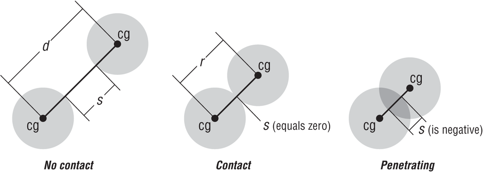
Penetration is important because if your objects overlap during the simulation, the results won’t look realistic—you’ll have one hovercraft moving inside the other. What you have to do is detect this penetration condition and then back up your simulation, reduce the time step, and try again. You keep doing this until they are no longer penetrating or they are within tolerance to be considered colliding.
You need to determine the normal velocity vector of the collision in order to calculate the collision impulse that will be used to simulate their response to the collision. For simple cases, determining this normal vector is fairly straightforward. In the case of particles or spheres, the collision normal is simply along the line that connects the centers of gravity of each colliding object; this is central impact, as discussed in Chapter 5, and is the same as that used for the particle example in Chapter 8.
Now take a look at the function we’ve prepared for this simulation to check for collisions:
int     CheckForCollision (pRigidBody2D body1, pRigidBody2D body2)
{
     Vector    d;
     float     r;
     int       retval = 0;
     float     s;
     Vector    v1, v2;
     float     Vrn;

     r = body1->ColRadius + body2->ColRadius;
     d = body1->vPosition - body2->vPosition;
     s = d.Magnitude() - r;

     d.Normalize();
     vCollisionNormal = d;

     v1 = body1->vVelocity;
     v2 = body2->vVelocity;
     vRelativeVelocity = v1 - v2;

     Vrn = vRelativeVelocity * vCollisionNormal;
     if((fabs(s) <= ctol) && (Vrn < 0.0))
     {
          retval = 1; // collision;
          CollisionBody1 = body1;
          CollisionBody2 = body2;
     } else      if(s < -ctol)
     {
          retval = −1; // interpenetrating
     } else
          retval = 0; // no collision

     return retval;
}
This function uses a simple bounding circle check to determine whether or not the hovercraft are colliding. The first thing it does
is calculate the distance, r, that represents the absolute
minimum separation between these hovercraft when they are in contact. ColRadius is the radius of the bounding circle of the hovercraft. We must compute
it for each hovercraft upon initialization as follows:
->ColRadius = SQRT(fLength*fLength + fWidth*fWidth);
Next, the distance separating the hovercraft at the time this function is called is
determined and stored in the variable d. Since we’re
assuming that these hovercraft are particles, determining d
is simply a matter of calculating the distance between the coordinates of each craft’s center
of gravity. In terms of vectors, this is simply the position vector of one craft minus the
position vector of the other.
Once the function has d and r, it needs to determine the actual amount of space, s, separating the hovercraft’s bounding circles. After this separation is
determined, the function normalizes the vector d. Since the
vector d is along the line that separates the hovercraft’s
centers of gravity, normalizing it yields the collision normal vector that we need for our
collision response calculations. The collision normal vector is saved in the global variable
vCollisionNormal.
After calculating the collision normal, this function goes on to determine the relative velocity between the hovercraft. In vector form, this is simply the
difference between the velocity vectors of each craft. Note that the velocity vectors used
here must be in global coordinates, not body-fixed (local) coordinates. Since what’s really
needed to determine if a collision is made is the relative normal velocity, the function proceeds to take the
vector dot product of the relative velocity and the collision normal vectors, saving the
result in the variable Vrn.
At this point, all of the calculations are complete, and the only thing left to do is make the appropriate checks to determine if there is a collision, penetration, or no collision at all.
The first check is to see if the hovercraft are colliding. We determine this by comparing
the absolute value of the separation between the hovercraft, s, with a distance tolerance, ctol. If the absolute value
of s is less than ctol,
a collision might be occurring. The second requirement is that the relative normal velocity be
negative, which implies that the points of impact on the hovercraft are moving toward each
other. If there is a collision, the function returns a 1 to
indicate that collision response is necessary.
If the hovercraft are found not to be colliding, then we perform a second check to see if
they’ve moved so close together that they are penetrating each other. In this case, if
s is less than –ctol,
the hovercraft are penetrating and the function returns a −1. If the hovercraft are not colliding and not penetrating, then the function
simply returns a 0, indicating that no further action is
required.
Before moving on, let’s say a word or two about ctol—the collision tolerance distance. This value is subject to tuning. There’s no
single value that works well in all cases. You must consider the overall sizes of the objects
potentially colliding, the step size you’re using, and how far the colliding objects are from
the viewer while being rendered (i.e., their scale). Basically, you should choose a value that
makes collisions look correct, so that on the one hand objects do not appear to be penetrating
each other, and on the other hand you do not report a collision when objects do not appear to
be touching at all.
Take a look now at the other new function, ApplyImpulse:
void     ApplyImpulse(pRigidBody2D body1, pRigidBody2D body2)
{
     float j;


     j =  (-(1+fCr) * (vRelativeVelocity*vCollisionNormal)) /
          ( (vCollisionNormal*vCollisionNormal) *
            (1/body1->fMass + 1/body2->fMass) );

     body1->vVelocity += (j * vCollisionNormal) / body1->fMass;
     body2->vVelocity -= (j * vCollisionNormal) / body2->fMass;
}
This is a simple but crucial function for collision response. What it does is calculate the linear collision impulse as a function of the colliding hovercraft’s relative normal velocity, masses, and coefficient of restitution, using the formula that we showed you in Chapter 5. Further, it applies this impulse to each hovercraft, effectively changing their velocities in response to the collision. Note that the impulse is applied to one hovercraft and then the negative impulse applied to the other.
With those two new functions complete, it’s now time to revise UpdateSimulation to handle collision detection and response as the simulation
steps through time. Here’s what the new UpdateSimulation
function looks like:
void     UpdateSimulation(float dt)
{
     float     dtime = dt;
     bool      tryAgain = true;
     int       check=0;
     RigidBody2D     craft1Copy, craft2Copy;
     bool      didPen = false;
     int       count = 0;


    Craft.SetThrusters(false, false);

    if (IsKeyDown(VK_UP))
        Craft.ModulateThrust(true);

    if (IsKeyDown(VK_DOWN))
        Craft.ModulateThrust(false);

    if (IsKeyDown(VK_RIGHT))
        Craft.SetThrusters(true, false);

    if (IsKeyDown(VK_LEFT))
        Craft.SetThrusters(false, true);


     while(tryAgain && dtime > tol)
     {
          tryAgain = false;
          memcpy(&craft1Copy, &Craft, sizeof(RigidBody2D));
          memcpy(&craft2Copy, &Craft2, sizeof(RigidBody2D));

          Craft.UpdateBodyEuler(dtime);
          Craft2.UpdateBodyEuler(dtime);

          CollisionBody1 = 0;
          CollisionBody2 = 0;
          check = CheckForCollision(&craft1Copy, &craft2Copy);

          if(check == PENETRATING)
          {
               dtime = dtime/2;
               tryAgain = true;
               didPen = true;
          } else if(check == COLLISION)
          {
               if(CollisionBody1 != 0 && CollisionBody2 != 0)
                    ApplyImpulse(CollisionBody1,  CollisionBody2);
          }
     }

     if(!didPen)
     {
          memcpy(&Craft, &craft1Copy, sizeof(RigidBody2D));
          memcpy(&Craft2, &craft2Copy, sizeof(RigidBody2D));
     }
}
Obviously, this version is more complicated than the original version. There’s one main reason for this: penetration could occur because the hovercraft can move far enough within a single time step to become overlapped. Visually, this situation is unappealing and unrealistic, so you should to try to prevent it.
The first thing this function does is enter a while
loop:
     while(tryAgain && dtime > tol)
     {
         .
         .
         .
     }
This loop is used to back up the simulation if penetration has occurred on the initial
time step. What happens is this: the function first tries to update the hovercraft and then
checks to see if there is a collision. If there is a collision, then it gets handled by
applying the impulse. If there is penetration, however, then you know the time step was too
big and you have to try again. When this occurs, tryAgain
is set to true, the time step is cut in half, and another
attempt is made. The function stays in this loop as long as there is penetration or until the
time step has been reduced to a size small enough to force an exit to the loop. The purpose of
this looping is to find the largest step size, less than or equal to dt, that can be taken and still avoid penetration. You either want a collision or
no collision.
You might ask yourself when does small become too small in terms of time step? Too small
is obviously when the time step approaches 0 and your entire simulation grinds to a halt.
Therefore, you may want to put in some criteria to exit this loop before things slow down too
much. This is all subject to tuning, by the way, and it also depends on the value you set for
ctol. We can’t stress enough the importance of tuning
these parameters. Basically, you must strive for visual realism while keeping your frame rates
up to required levels.
Looking inside this while loop reveals what’s going on.
First, tryAgain is set to false, optimistically assuming that there will be no penetration, and we make
copies of the hovercraft’s states, reflecting the last successful call to UpdateSimulation.
Next, we make the usual call to UpdateBody for each
copy of the hovercraft. Then a call to the collision detection function, CheckForCollision, is made to see if Craft is colliding with or penetrating Craft2.
If there is penetration, then tryAgain is set to true, dtime is cut in half,
didPen is set to true,
and the function takes another lap through the while loop.
didPen is a flag that lets us know that a penetration
condition did occur.
If there was a collision, the function handles it by applying the appropriate impulse:
     if(CollisionBody1 != 0 && CollisionBody2 != 0)
          ApplyImpulse(CollisionBody1,  CollisionBody2);
After getting through the while loop, the updated
hovercraft states are saved and UpdateSimulation is
complete.
The last bit of code you need to add includes a few new global variables and defines:
#define     LINEARDRAGCOEFFICIENT        0.25f
#define     COEFFICIENTOFRESTITUTION     0.5f
#define     COLLISIONTOLERANCE           2.0f

Vector      vCollisionNormal;
Vector      vRelativeVelocity;
float       fCr = COEFFICIENTOFRESTITUTION;
float const ctol = COLLISIONTOLERANCE;
The only one we haven’t mentioned so far, although you’ve seen it in ApplyImpulse, is fCr, the
coefficient of restitution. Here we have it set to 0.5, which means that the collisions are
halfway between perfectly elastic and perfectly inelastic (refer back to our earlier
discussions on coefficients of restitution in Chapter 5 if you’ve forgotten
these terms). This is one of those parameters that you’ll have to tune to get the desired
behavior.
While we’re on the subject of tuning, we should mention that you’ll also have to play with the linear drag coefficient used to calculate the drag force on the hovercraft. While this coefficient is used to simulate fluid dynamic drag, it also plays an important role in terms of numerical stability. You need some damping in your simulation so that your integrator does not blow up—that is, damping helps keep your simulation stable.
That’s pretty much it as far as implementing basic collision response. If you run this example, you’ll be able to drive the hovercraft into each other and bounce off accordingly. You can play around with the mass of each hovercraft and the coefficient of restitution to see how the craft behave when one is more massive than the other, or when the collision is somewhere between perfectly elastic and perfectly inelastic.
You may notice that the collision response in this example sometimes looks a little strange. Keep in mind that’s because this collision response algorithm, so far, assumes that the hovercraft are round when in fact they are rectangular. This approach will work just fine for round objects like billiard balls, but to get the level of realism required for non-round rigid bodies you need to include angular effects. We’ll show you how to do that in the next section.
Angular Effects
Including angular effects will yield more realistic collision responses for these rigid bodies, the
hovercraft. To get this to work, you’ll have to make several changes to ApplyImpulse and CheckForCollision;. UpdateSimulation will
remain unchanged. The more extensive changes are in CheckForCollision, so we’ll discuss it first.
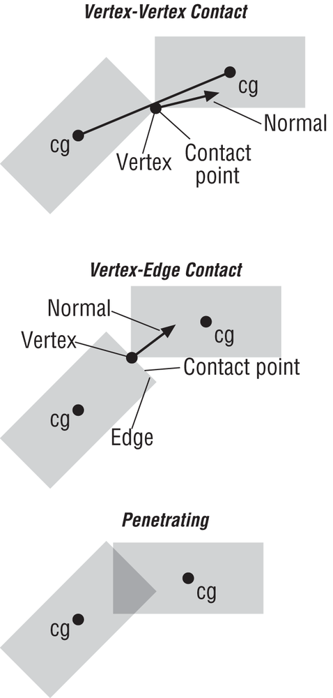
The new version of CheckForCollision will do more than
a simple bounding circle check. Here, each hovercraft will be represented by a polygon with
four edges and four vertices, and the types of contact that will be checked for are
vertex-vertex and vertex-edge contact (see Figure 10-2).[19]
In addition to the tasks discussed in the last section, this new version of CheckForCollision must also determine the exact point of contact
between the hovercraft. This is a very important distinction between this new version and the
last. You need to know the point of contact because in order to affect the angular velocity,
you must apply the impulse at the point of contact. In the last section, the normal to the
contact point always passed through the center of gravity of the hovercraft because we assumed
they were spheres; that’s not the case here.
This now brings up the challenge of finding the collision normal. There are two cases to consider here. In edge-vertex collisions, the normal is always perpendicular to the edge that’s involved in the collision. In vertex-vertex collisions, however, the normal is ambiguous, so we’ve resorted to taking the normal parallel to the line connecting the hovercraft’s centers of gravity.
All of these considerations make CheckForCollisions a
little more involved than in the previous section. The following code listing shows what we
mean:
int     CheckForCollision(pRigidBody2D body1, pRigidBody2D body2)
{
     Vector    d;
     float     r;
     int       retval = 0;
     float     s;
     Vector    vList1[4], vList2[4];
     float     wd, lg;
     int       i,j;
     bool      haveNodeNode = false;
     bool      interpenetrating = false;
     bool      haveNodeEdge = false;
     Vector    v1, v2, u;
     Vector    edge, p, proj;
     float     dist, dot;
     float     Vrn;

     // First check to see if the bounding circles are colliding
     r = body1->fLength/2 + body2->fLength/2;
     d = body1->vPosition - body2->vPosition;
     s = d.Magnitude() - r;

     if(s <= ctol)
     {   // We have a possible collision, check further
          // build vertex lists for each hovercraft
          wd = body1->fWidth;
          lg = body1->fLength;
          vList1[0].y = wd/2;          vList1[0].x = lg/2;
          vList1[1].y = -wd/2;         vList1[1].x = lg/2;
          vList1[2].y = -wd/2;         vList1[2].x = -lg/2;
          vList1[3].y = wd/2;          vList1[3].x = -lg/2;

          for(i=0; i<4; i++)
          {
               VRotate2D(body1->fOrientation, vList1[i]);
               vList1[i] = vList1[i] + body1->vPosition;
          }

          wd = body2->fWidth;
          lg = body2->fLength;
          vList2[0].y = wd/2;          vList2[0].x = lg/2;
          vList2[1].y = -wd/2;         vList2[1].x = lg/2;
          vList2[2].y = -wd/2;         vList2[2].x = -lg/2;
          vList2[3].y = wd/2;          vList2[3].x = -lg/2;

          for(i=0; i<4; i++)
          {
               VRotate2D(body2->fOrientation, vList2[i]);
               vList2[i] = vList2[i] + body2->vPosition;
          }

          // Check for vertex-vertex collision
          for(i=0; i<4 && !haveNodeNode; i++)
          {
               for(j=0; j<4 && !haveNodeNode; j++)
               {

                    vCollisionPoint = vList1[i];
                    body1->vCollisionPoint = vCollisionPoint −
                                             body1->vPosition;

                    body2->vCollisionPoint = vCollisionPoint −
                                             body2->vPosition;

                    vCollisionNormal = body1->vPosition −
                                       body2->vPosition;

                    vCollisionNormal.Normalize();

                    v1 = body1->vVelocityBody +
                        (body1->vAngularVelocity^body1->vCollisionPoint);

                    v2 = body2->vVelocityBody +
                        (body2->vAngularVelocity^body2->vCollisionPoint);

                    v1 = VRotate2D(body1->fOrientation, v1);
                    v2 = VRotate2D(body2->fOrientation, v2);

                    vRelativeVelocity = v1 - v2;
                    Vrn = vRelativeVelocity * vCollisionNormal;

                    if( ArePointsEqual(vList1[i],
                                       vList2[j]) &&
                        (Vrn < 0.0) )
                         haveNodeNode = true;

               }
          }

          // Check for vertex-edge collision
          if(!haveNodeNode)
          {
               for(i=0; i<4 && !haveNodeEdge; i++)
               {
                    for(j=0; j<3 && !haveNodeEdge; j++)
                    {
                         if(j==2)
                              edge = vList2[0] - vList2[j];
                         else
                              edge = vList2[j+1] - vList2[j];
                         u = edge;
                         u.Normalize();

                         p = vList1[i] - vList2[j];
                         proj = (p * u) * u;

                         d = p^u;
                         dist = d.Magnitude();

                         vCollisionPoint = vList1[i];
                         body1->vCollisionPoint = vCollisionPoint −
                                                  body1->vPosition;

                         body2->vCollisionPoint = vCollisionPoint −
                                                  body2->vPosition;

                         vCollisionNormal = ((u^p)^u);
                         vCollisionNormal.Normalize();

                         v1 = body1->vVelocityBody +
                             (body1->vAngularVelocity ^
                              body1->vCollisionPoint);

                         v2 = body2->vVelocityBody +
                             (body2->vAngularVelocity ^
                              body2->vCollisionPoint);

                         v1 = VRotate2D(body1->fOrientation, v1);
                         v2 = VRotate2D(body2->fOrientation, v2);

                         vRelativeVelocity = (v1 - v2);
                         Vrn = vRelativeVelocity * vCollisionNormal;

                         if( (proj.Magnitude() > 0.0f) &&
                             (proj.Magnitude() <= edge.Magnitude()) &&
                             (dist <= ctol) &&
                             (Vrn < 0.0) )
                              haveNodeEdge = true;
                    }
               }
          }

          // Check for penetration
          if(!haveNodeNode && !haveNodeEdge)
          {
               for(i=0; i<4 && !interpenetrating; i++)
               {
                    for(j=0; j<4 && !interpenetrating; j++)
                    {
                         if(j==3)
                              edge = vList2[0] - vList2[j];
                         else
                              edge = vList2[j+1] - vList2[j];

                         p = vList1[i] - vList2[j];
                         dot = p * edge;
                         if(dot < 0)
                         {
                              interpenetrating = true;
                         }
                    }
               }
       }

       if(interpenetrating)
       {
               retval = −1;
       } else if(haveNodeNode || haveNodeEdge)
       {
               retval = 1;
       } else
               retval = 0;

     } else
     {
          retval = 0;
     }

     return retval;
}
The first thing that CheckForCollision does is perform
a quick bounding-circle check to see if there is a possible collision. If no collision is
detected, the function simply exits, returning 0. This is
the same bounding-circle check performed in the earlier version:
     r = body1->fLength/2 + body2->fLength/2;
     d = body1->vPosition - body2->vPosition;
     s = d.Magnitude() - r;

     if(s <= ctol)
     {
          .
          .
          .
     } else
          retval = 0;
     }
If the bounding-circle check indicates the possibility of a collision, then CheckForCollision proceeds by setting up a couple of polygons,
represented by vertex lists, for each hovercraft:
          wd = body1->fWidth;
          lg = body1->fLength;
          vList1[0].y = wd/2;          vList1[0].x = lg/2;
          vList1[1].y = -wd/2;         vList1[1].x = lg/2;
          vList1[2].y = -wd/2;         vList1[2].x = -lg/2;
          vList1[3].y = wd/2;          vList1[3].x = -lg/2;

          for(i=0; i<4; i++)
          {
               VRotate2D(body1->fOrientation, vList1[i]);
               vList1[i] = vList1[i] + body1->vPosition;
          }

          wd = body2->fWidth;
          lg = body2->fLength;
          vList2[0].y = wd/2;          vList2[0].x = lg/2;
          vList2[1].y = -wd/2;         vList2[1].x = lg/2;
          vList2[2].y = -wd/2;         vList2[2].x = -lg/2;
          vList2[3].y = wd/2;          vList2[3].x = -lg/2;
          for(i=0; i<4; i++)
          {
               VRotate2D(body2->fOrientation, vList2[i]);
               vList2[i] = vList2[i] + body2->vPosition;
          }
The vertex lists are initialized in unrotated body-fixed (local) coordinates based on the length and width of the hovercraft. The vertices are then rotated to reflect the orientation of each hovercraft. After that, the position of each hovercraft is added to each vertex to convert from local coordinates to global coordinates
Checking first for vertex-vertex collisions, the function iterates through each vertex in one list, comparing it with each vertex in the other list to see if the points are coincident.
          // Check for vertex-vertex collision
          for(i=0; i<4 && !haveNodeNode; i++)
          {
               for(j=0; j<4 && !haveNodeNode; j++)
               {

                    vCollisionPoint = vList1[i];
                    body1->vCollisionPoint = vCollisionPoint −
                                             body1->vPosition;

                    body2->vCollisionPoint = vCollisionPoint −
                                             body2->vPosition;

                    vCollisionNormal = body1->vPosition −
                                       body2->vPosition;

                    vCollisionNormal.Normalize();

                    v1 = body1->vVelocityBody +
                        (body1->vAngularVelocity^body1->vCollisionPoint);

                    v2 = body2->vVelocityBody +
                        (body2->vAngularVelocity^body2->vCollisionPoint);

                    v1 = VRotate2D(body1->fOrientation, v1);
                    v2 = VRotate2D(body2->fOrientation, v2);

                    vRelativeVelocity = v1 - v2;
                    Vrn = vRelativeVelocity * vCollisionNormal;

                    if( ArePointsEqual(vList1[i],
                                       vList2[j]) &&
                                       (Vrn < 0.0) )
                         haveNodeNode = true;

               }
          }
This comparison makes a call to another new function, ArePointsEqual:
                    if( ArePointsEqual(vList1[i],
                                       vList2[j]) &&
                                       (Vrn < 0.0) )
                         haveNodeNode = true;
ArePointsEqual simply checks to see if the points are
within a specified distance from each other, as shown here:
bool     ArePointsEqual(Vector p1, Vector p2)
{
     // Points are equal if each component is within ctol of each other
     if(  (fabs(p1.x - p2.x) <= ctol) &&
          (fabs(p1.y - p2.y) <= ctol) &&
          (fabs(p1.z - p2.z) <= ctol) )
          return true;
     else
          return false;
}
Within the nested for loops of the vertex-vertex check,
we perform a number of important calculations to determine the collision normal vector and
relative velocity that are required for collision response.
First, we calculate the collision point, which is simply the coordinates of a vertex that is involved in the collision. Note that this point will be in global coordinates, so it will have to be converted to local coordinates for each hovercraft in order to be useful for collision response. Here’s how that’s done:
                    vCollisionPoint = vList1[i];
                    body1->vCollisionPoint = vCollisionPoint −
                                             body1->vPosition;

                    body2->vCollisionPoint = vCollisionPoint −
                                             body2->vPosition;
The second calculation is aimed at determining the collision normal vector, which for
vertex-vertex collisions we’ve assumed is along the line connecting the centers of gravity of
each hovercraft. The calculation is the same as that shown in the earlier version of CheckForCollision:
                    vCollisionNormal = body1->vPosition −
                                       body2->vPosition;

                    vCollisionNormal.Normalize();
The third and final calculation is aimed at determining the relative velocity between the points of impact. This is an important distinction from the earlier version, since the velocities of the points of impact on each body are functions of the linear and angular velocities of the hovercraft:
                    v1 = body1->vVelocityBody +
                        (body1->vAngularVelocity^body1->vCollisionPoint);

                    v2 = body2->vVelocityBody +
                        (body2->vAngularVelocity^body2->vCollisionPoint);

                    v1 = VRotate2D(body1->fOrientation, v1);
                    v2 = VRotate2D(body2->fOrientation, v2);

                    vRelativeVelocity = v1 - v2;
                    Vrn = vRelativeVelocity * vCollisionNormal;
Here, v1 and v2
represent the velocities of the points of collision relative to each hovercraft in local
coordinates, which are then converted to global coordinates. Once we’ve obtained the relative
velocity, vRelativeVelocity, we obtain the relative normal
velocity, Vrn, by taking the dot product of the relative
velocity with the collision normal vector.
If there is no vertex-vertex collision, CheckForCollision proceeds to check for vertex-edge collisions:
          // Check for vertex-edge collision
          if(!haveNodeNode)
          {
               for(i=0; i<4 && !haveNodeEdge; i++)
               {
                    for(j=0; j<3 && !haveNodeEdge; j++)
                    {
                         if(j==3)
                              edge = vList2[0] - vList2[j];
                         else
                              edge = vList2[j+1] - vList2[j];
                         u = edge;
                         u.Normalize();

                         p = vList1[i] - vList2[j];
                         proj = (p * u) * u;

                         d = p^u;
                         dist = d.Magnitude();

                         vCollisionPoint = vList1[i];
                         body1->vCollisionPoint = vCollisionPoint −
                                                  body1->vPosition;

                         body2->vCollisionPoint = vCollisionPoint −
                                                  body2->vPosition;

                         vCollisionNormal = ((u^p)^u);
                         vCollisionNormal.Normalize();

                         v1 = body1->vVelocityBody +
                             (body1->vAngularVelocity ^
                              body1->vCollisionPoint);

                         v2 = body2->vVelocityBody +
                             (body2->vAngularVelocity ^
                              body2->vCollisionPoint);

                         v1 = VRotate2D(body1->fOrientation, v1);
                         v2 = VRotate2D(body2->fOrientation, v2);

                         vRelativeVelocity = (v1 - v2);
                         Vrn = vRelativeVelocity * vCollisionNormal;

                         if( (proj.Magnitude() > 0.0f) &&
                             (proj.Magnitude() <= edge.Magnitude()) &&
                             (dist <= ctol) &&
                             (Vrn < 0.0) )
                              haveNodeEdge = true;
                    }
               }
          }
Here, the nested for loops check each vertex in one
list to see if it is in contact with each edge built from the vertices in the other list.
After building the edge under consideration, we save and normalize a copy of it to represent a
unit vector pointing along the edge:
                         if(j==3)
                              edge = vList2[0] - vList2[j];
                         else
                              edge = vList2[j+1] - vList2[j];
                         u = edge;
                         u.Normalize();
Variable u represents that unit vector, and it will be
used in subsequent calculations. The next set of calculations determines the location of the
projection of the vertex under consideration onto the edge under consideration, as well as the
minimum distance from the vertex to edge:
p = vList1[i] - vList2[j];
proj = (p * u) * u;
d = p^u;
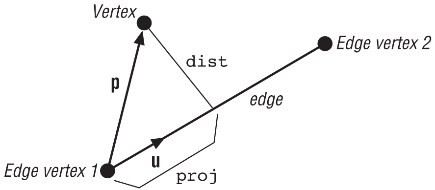
dist = d.Magnitude();Variable p is a vector from the first vertex on the
edge to the vertex under consideration, and proj is the
distance from the first edge vertex, along the edge, to the point upon which the vertex
projects. dist is the minimum distance from the vertex to
the edge. Figure 10-3 illustrates this geometry.
If there is a collision, the global location of the point of impact is equal to the vertex under consideration, which we must convert to local coordinates for each hovercraft, as shown here:
                         vCollisionPoint = vList1[i];
                         body1->vCollisionPoint = vCollisionPoint −
                                                  body1->vPosition;

                         body2->vCollisionPoint = vCollisionPoint −
                                                  body2->vPosition;
Since, in this type of collision, the collision normal vector is perpendicular to the
edge, you can determine it by taking the result of the cross product of u and p and crossing it with
u as follows:
                         vCollisionNormal = ((u^p)^u);
                         vCollisionNormal.Normalize();
These calculations give you a unit length vector in the plane of vectors u and p and perpendicular to
the edge.
Next, the relative velocity between the points of impact on each hovercraft is determined, just as in the vertex-vertex collision check:
                         v1 = body1->vVelocityBody +
                             (body1->vAngularVelocity ^
                              body1->vCollisionPoint);

                         v2 = body2->vVelocityBody +
                             (body2->vAngularVelocity ^
                              body2->vCollisionPoint);

                         v1 = VRotate2D(body1->fOrientation, v1);
                         v2 = VRotate2D(body2->fOrientation, v2);

                         vRelativeVelocity = (v1 - v2);
                         Vrn = vRelativeVelocity * vCollisionNormal;
In determining whether or not the vertex under consideration is in fact colliding with an edge, you have to check to see if the distance from the vertex is within your collision tolerance, and you also have to make sure the vertex actually projects onto the edge (that is, it does not project beyond the endpoints of the edge). Additionally, you need to make sure the relative normal velocity indicates that the points of contact are moving toward each other. Here’s how this check looks:
                         if( (proj.Magnitude() > 0.0f) &&
                             (proj.Magnitude() <= edge.Magnitude()) &&
                             (dist <= ctol) &&
                             (Vrn < 0.0) )
                              haveNodeEdge = true;
After CheckForCollision checks for vertex-vertex and
vertex-edge collisions, it goes on to check for penetration:
          if(!haveNodeNode && !haveNodeEdge)
          {
               for(i=0; i<4 && !interpenetrating; i++)
               {
                    for(j=0; j<4 && !interpenetrating; j++)
                    {
                         if(j==3)
                              edge = vList2[0] - vList2[j];
                         else
                              edge = vList2[j+1] - vList2[j];

                         p = vList1[i] - vList2[j];
                         dot = p * edge;
                         if(dot < 0)
                         {
                              interpenetrating = true;
                         }
                    }
               }
       }
This check is a standard point-in-polygon check using the vector dot product to determine
if any vertex of one polygon lies within the bounds of the other polygon. After this check,
the function simply returns the appropriate result. Here again, 0 indicates no collision or penetration, 1
indicates a collision, and −1 indicates penetration.
With CheckForCollision out of the way, turn your
attention to ApplyImpulse, which also has to be revised to
include angular effects. Specifically, you need to use the impulse formula that includes
angular as well as linear effects (see Chapter 5), and you also have to
apply the impulse to the hovercraft’s angular velocities in addition to their linear
velocities. Here’s how the new ApplyImpulse function
looks:
void     ApplyImpulse(pRigidBody2D body1, pRigidBody2D body2)
{
     float j;

     j = (-(1+fCr) * (vRelativeVelocity*vCollisionNormal)) /
          ( (1/body1->fMass + 1/body2->fMass) +
          (vCollisionNormal * (((body1->vCollisionPoint ^
           vCollisionNormal)/body1->fInertia)^body1->vCollisionPoint)) +
          (vCollisionNormal * (((body2->vCollisionPoint ^
           vCollisionNormal)/body2->fInertia)^body2->vCollisionPoint))
          );

     body1->vVelocity += (j * vCollisionNormal) / body1->fMass;
     body1->vAngularVelocity += (body1->vCollisionPoint ^
                                 (j * vCollisionNormal)) /
                                 body1->fInertia;

     body2->vVelocity -= (j * vCollisionNormal) / body2->fMass;
     body2->vAngularVelocity -= (body2->vCollisionPoint ^
                                 (j * vCollisionNormal)) /
                                 body2->fInertia;
}
Remember, the impulse is applied to one hovercraft while its negative is applied to the other.
That does it for this new version of the hovercraft simulation. If you run the program now, you’ll see that you can crash the hovercraft into each other and they bounce and rotate accordingly. This makes for a much more realistic simulation than the simple, linear collision response approach of the last section. Here again, you can play with the mass of each hovercraft and the coefficient of restitution to see how these parameters affect the collision response between the hovercraft.