
Chapter 24. 3D Display
For all the work we’ve done to make programs’ graphics more realistic, the best we can do is project our realistic simulations onto a two-dimensional screen. Although graphics libraries such as Microsoft DirectX and OpenGL can provide photorealistic renderings in real time, they still lack the ability to truly immerse the user in the works you have so carefully created. Three-dimensional display is something that the entertainment industry has attempted to make standard for some time. In reality, almost all “three-dimensional” display technologies are what are technically called stereoscopic displays. These displays use the way in which your eyes perceive depth to trick your brain into thinking it is seeing a three-dimensional image while the display remains two-dimensional. In contrast, displays that actually involve creating a rendering in three dimensions are called volumetric displays. We’ll cover these later as part of our effort to discuss emerging technologies.
Binocular Vision
The trick to displaying objects so that they appear to be three-dimensional depends on the method by which the human brain perceives the world around it. Indeed, animals that have two eyes engage in what is called binocular vision. Because each eye is in a slightly different position relative to the objects it is viewing, the left and right eye provide an image that is distinct to the brain. This is called binocular disparity. There are three possible results when the brain encounters these two different images: suppression, fusion, or summation. Suppression is when the brain ignores one of the images, summation is when the brain tries to perceive both images at the same time (double vision), and finally fusion is mixing the two images to create a depth of field. The process of binocular fusion is something our brain learns to do when we are first born.
Note
Given the way that eyes focus light, we are born seeing the world upside down! After a few days, our brains instinctively flip the images over so that the motion of our hands matches the motion that we observe. There have even been tests where people wearing glasses that invert your vision will eventually see the images right side up. When they take off the glasses, everything looks upside down again until their brain has time to correct the image.
Binocular fusion is also a learned behavior of the brain. The visual cortex takes the independent visual information from each eye and fuses it into a single image. Your brain does this as a way of organically calculating the distance to objects so that you can efficiently interact with the three-dimensional world. The exact process by which your brain accomplishes this is an area of active research. In fact, researchers have found that two images need not have any geometrical disparity in order to be fused. That is, if you take the exact same photograph of the same object and the same angle, but with different lighting, the shadows being cast can also cause the brain to recreate the object in three dimensions.
Parallax is the distance an object moves between the left- and right-eye images. You can easily demonstrate it by holding your thumb six inches from your face and closing one of your eyes. Block some of the words on this page with your thumb. Now open that eye and close the other one. The words that were behind your thumb should now be visible. This is because your eyes are not in the same position, so the different angles provide slightly different pictures of the page. This distance your thumb appeared to move is the parallax at that distance from your eye.
Fusion is a little harder to achieve, but Figure 24-1 provides an interesting example. The two circles are set a specific distance apart and show the top of a truncated cone coming out of the page. The top of the cone is offset compared to the bottom. This offset is in opposite directions, mimicking how your eyes would see it if you were directly over the cylinder.
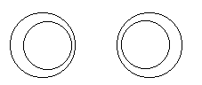
The best way to view the stereopair shown in Figure 24-1 is to begin by looking above this book at a far-off object. Now lower your gaze without refocusing your eyes and stare between the two sets of circles. With some trying, your brain should be able to fuse the images so that there are now three sets of circles. The original two will be out of focus, and the center set should appear to be three-dimensional. You can also get the sets to fuse by crossing your eyes; however, this is much less comfortable than using your eyes in their distance-viewing configuration.
Given that your brain is excellent at real-time pattern recognition, it can also compare visual information over time to get a sense of size and relative distance. This is called movement parallax, and it causes objects that are closer to you to appear to move faster when you move your head than objects that are farther away. For example, if you are driving in a car, you’ll notice that the trees appear to move faster than the moon. This is because the trees are very close in comparison to the moon. Your brain uses this apparent speed disparity to help conclude that the moon is very far away indeed. In the next chapter we’ll discuss how computer algorithms attempt this sort of pattern recognition.
In fact, according to Flight Simulation (edited by J. M. Rolfe and K. J. Staples; Cambridge University Press), the process of 3D visualization depends on the following eight major factors.
Occlusion of one object by another
Subtended visual angle of an object of known size
Linear perspective (convergence of parallel edges)
Vertical position (objects higher in the scene generally tend to be perceived as farther away)
Haze, desaturation, and a shift to bluishness
Change in size of textured pattern detail
Accommodation of the eyeball (eyeball focus)
A standard 3D graphics library is capable of giving the appearance of three dimensions on the screen, just as any good painter on a canvas. Both standard 3D libraries and painters do their job by recreating the first six items in the preceding list. To further the illusion, 3D display technology simulates the seventh, stereopsis. Stereopsis is impression of depth generated by the fact that you have two eyeballs looking at slightly different angles. In short, the graphics library renders two different images, one for each eye, that have a parallax shift. These images are then delivered to each eye separately. The method by which the images are segregated varies from technology to technology. We will discuss these in a little bit.
The last item on the list, accommodation of the eyeball, is the process by which your eye changes shape to focus at different distances. By correlating the shape of your eye with the distance to the object, accommodation works as one of the pieces of information your brain uses to determine depth. As current 3D displays still use a 2D screen, the eyes are still focusing on the same plane regardless of the object’s perceived depth; therefore, the eighth item in the list is not recreated. This is why most 3D displays still do not seem completely real. Some technologies, such as holograms and volumetric displays, allow for accommodation of the eyeball, but usually at the expense of some other factor. We’ll touch on these beyond state-of-the-art technologies near the end of the chapter.
Stereoscopic Basics
There are some extra considerations when it comes using today’s 3D display technologies to recreate the images that would usually be provided to the visual cortex by binocular vision. Normally two eyes create two images that the brain combines with a biological depth map. The earliest stereoscopic images were generated in the 1800s from two photographs taken from slightly different positions. The viewer would then look at the photos through what came to be known as a stereoscope. This device was essentially an early example of the View-Master that some of you might remember from childhood. While the principle of showing unique images to each eye is straightforward in this case, it doesn’t allow group viewing and requires that the user have something pressed against his eyes. To make 3D display something that a group of people can all experience together and in some cases even without the aid of any headgear, we must look at some more sophisticated methods of segregating the right and left images.
The Left and Right Frustums
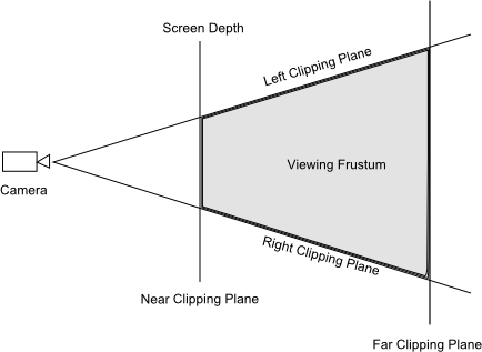
If you are familiar with computer graphics, the concept of the viewing frustum is not alien to you. If you aren’t, we’ll take a second to go over it, but it might be worthwhile to read about it in detail before you continue. The viewing frustum is the region of space in the model world that the camera can see from its given position in that world. In a normal 3D graphic rendering, the frustum is clipped by a near plane that represents the screen distance. In essence, you cannot render something closer to the user than the screen plane. If you remember things jumping out of the screen in the last 3D movie you saw, you can probably guess that when we are using stereoscopic rendering, this no longer holds true. A normal computer graphics frustum is shown in Figure 24-2.
When using a stereoscopic 3D display library, we no longer have a single viewing frustum. Instead we have two cameras that are horizontally displaced from the 2D camera, as shown in Figure 24-3.
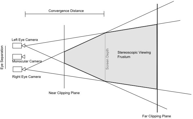
These two cameras, offset from the monocular camera, generate a left and right frustums. As you can see, there is a location where these two frustums intersect; this is called the convergence distance. Objects that are placed at the convergence distance will have the same appearance to both cameras. Note that the cameras are all pointed in the same direction; this is called the off-axis method. This requires the frustums to be asymmetric, which most modern graphics libraries support. Now, at first glance, it might be tempting to toe-in the two frustums so that each camera’s frustums are symmetrical, as shown in Figure 24-4.
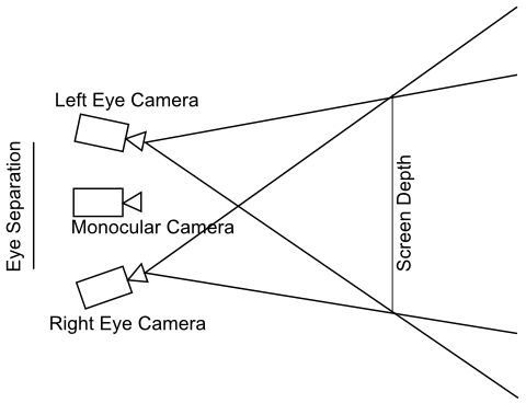
This will create workable stereopairs, but along with the horizontal parallax will introduce some vertical parallax. This can cause eyestrain to the viewer and should be avoided. Instead, the off-axis technique should be used; it is illustrated in Figure 24-5. One of the objects is beyond the screen in the background, and one is in front of the screen.
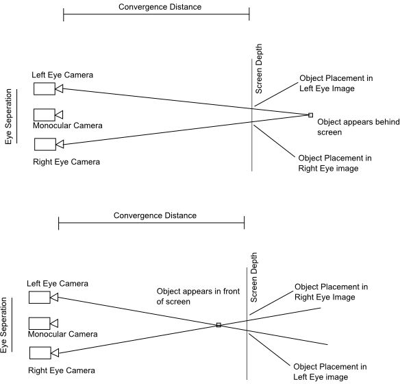
You can see that if you wish to move something to greater than screen depth, the object must be shown farther to the left than if it were at screen depth for the left eye image. For the right eye image, the object must be shown farther to the right. If you want to show something coming out of the screen, the opposite is true. The left eye will see the object as farther to the right than if it were at screen depth. Also note that each object will have a slightly different angle as well. Again, the distance between the right eye image placement and the left eye image placement is referred to as parallax. The amount and relative orientation of parallax is the chief way your brain creates 3D images. In fact, the most important aspect of the physics of stereoscopic display for programmers to understand is that there is a parallax budget that they must use wisely in developing programs that take advantage of 3D display. This budget defines the ranges of parallax that your viewer’s brain will be able to accept comfortably. We’ll discuss this in detail at the end of the chapter.
For now, we’ll consider that if we were to just show the right and left images on a screen without further work, you’d end up seeing two images with both eyes and no 3D effect would be produced. It is paramount that the image intended for the left eye is seen only by the left eye and vice versa. These two channels, the left and right eye, must be kept as separate as possible. Let’s see what the current options are for achieving such separation.
Types of Display
As just explained, 3D display technology depends on providing two distinct images, one to each eye. In the next sections we’ll discuss the common techniques used today.
Complementary-Color Anaglyphs
Anyone who saw a 3D movie in the 80s remembers the cheap red and blue glasses one had to wear to get the effect. These were complementary-color anaglyphs. An anaglyph is the technique of encoding the separate images in a single photograph or video frame using color filters. The method calls for two horizontally shifted images to be viewed simultaneously. The images will contain the two images tinted in opposite colors of the scheme. While there are many color combinations that can be used, the most common today are red and cyan. These colors are chosen because the cyan and red filters are the most exclusive. Red and green filters were used earlier, but the green filter allows too much red light to leak through. This can cause what is called binocular rivalry, where your brain has a hard time figuring out which depth map to use. One way to illustrate this is via the simple drawing of a transparent cube, as shown in Figure 24-6.
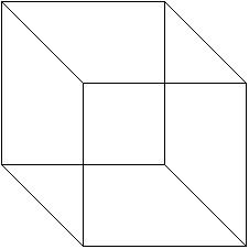
If you focus on the cube in Figure 24-6, your brain may start to flip between interpreting the upper face as forward of the lower face, and the lower face being forward. While this is caused by incomplete depth cues, the same uneasy feeling can be caused when your brain receives leaks across the two channels in a stereoscopic display. As you can imagine, this would be pretty annoying during a video game.
As the glasses don’t require any electronics to do this, it is an example of passive 3D technology. The major drawback of this method is that the red component of the images is muted to the viewer. There are many improvements that can be made to the system to correct the color and account for some fuzziness. One example is the patented ColorCode 3D, which uses amber and blue filters. The advantage of this system is a nearly full color space and a fairly good image when not viewed with the glasses.
Anaglyphs fell out of favor with movie and game producers when polarization techniques came into maturity. These produce better color reproduction and reduce eyestrain. However, given the relatively inexpensive glasses required and that nothing special is required of the display other than that it be capable of displaying colors, anaglyphs have had a resurgence in printed material and online.
Linear and Circular Polarization
As polarized light plays a very important part in the largest 3D displays, movie screens, we’ll review what polarization of light means and how to accomplish it. Light can be thought of as an electromagnetic wave traveling through space. Let’s begin our discussion by considering a common light bulb. It emits electromagnetic waves in all directions and is nominally “white.” An electromagnetic wave oscillates perpendicularly to its line of travel. This is called a transverse wave. In comparison, sound waves oscillate in the same direction they travel, creating regions of higher density. These are called longitudinal waves. Only transverse waves can be polarized because only transverse waves have oscillation in multiple orientations. Going back to our light bulb, it is emitting “dirty” light in that the electromagnetic waves are all at random orientations.
Most sources of electromagnetic radiation (i.e., light) are composed of many molecules that all have different orientations when they emit light, so the light is unpolarized. If that light passes through a polarization filter, it leaves the filter with the oscillations in only one direction. In fact, there are two types of filters. Linear filters produce oscillations in one direction. Circular filters (a special case of elliptical filters) create circularly polarized light that rotates in an either righthand or lefthand direction. As circular filters depend on linear filters first, we’ll discuss those now.
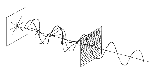
The simplest and most common linear filter is the wire-grid polarizer. Imagine many very fine wires running parallel to one another with small gaps between them, as shown in Figure 24-7. When unpolarized light hits the wires, the oscillations that are parallel to the waves excite the electrons in the wire and move them along the length of the wire. This phenomenon causes that component of the oscillations to be reflected. However, the electrons cannot easily move perpendicular to the length of the wires, so the reflection phenomenon doesn’t occur. What we are left with on the far side of the filter is a beam of light with the oscillations all in the same direction.
Early 3D display systems used linearly polarized light to separate the right eye channel from the left eye channel. However, there is one problem with using linear polarizers. It follows that if you place another wire-grid polarizer after the first, with its wires rotated 90 degrees, no light will pass through! In fact, if you have an old pair of sunglasses or 3D glasses and you hold the right eye lens against the left eye lens, you won’t be able to see anything. That is because each filter is blocking out one direction of oscillations, preventing any light from coming through. If you rotated one of the lenses, then the combined lens will lighten as you align the polarization directions. The problem with these types of lenses is that if you were watching a movie and tilted your head to one side, the same effect would occur and the image would be greatly dimmed. This means your date could no longer rest his or her head on your shoulder while watching the movie. Something had to be done.
Circular polarization is another form of filtering out certain orientations so that you can control which light beams pass through which lens. However, in this case the direction of oscillation is not a single orientation but more accurately a pattern of oscillations parameterized by time. The first step to achieve circular polarization is to send the light through a linear polarizer as just discussed. That light is then sent through what is known as a quarter-wave filter. A typical arrangement is shown in Figure 24-8.
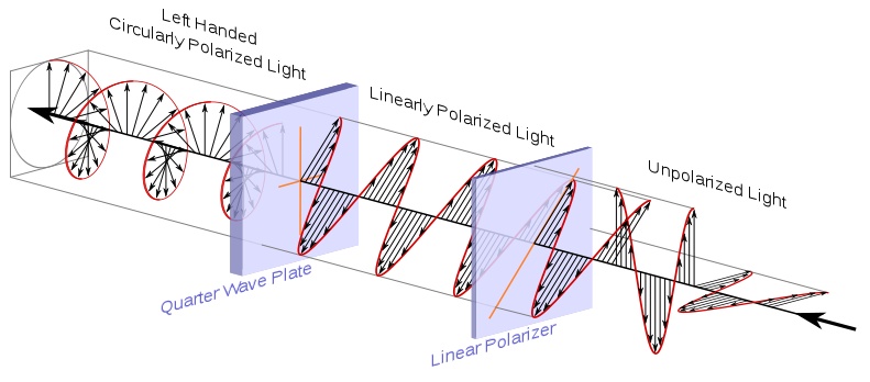
First a linear polarizer rotated to 45 degrees accepts incoming light and polarizes as we discussed earlier. The circular polarization effect is accomplished when a light wave polarized at 45 degrees hits the filter that accepts both 0- and 90-degree oscillations. As previously noted, this is called a quarter-wave filter. The resulting combination of 0- and 90-degree components of the intermediate 45-degree beam results in oscillations that turn right or left in a regular pattern. Patterns that turn counterclockwise are called left-handed. Patterns that turn clockwise are called right-handed.
The main benefit is that the lenses create the same pattern regardless of their rotation about the center of the lens. In other words, if you rotated the assembly shown in Figure 24-8, meaning both lenses about the center axis, there will be no change in the polarization. This reduces the effect of head position on the viewer’s ability to fuse the right and left eye channels, reducing eyestrain and increasing comfort. As a side note, it is also required for use in digital cameras, as linear polarization would affect the autofocus and light-metering features of SLRs.
Like anaglyphs, polarized 3D systems also use glasses to separate two channels that are projected at the same time. The first systems used two projectors, each with a different linear polarization filter projecting on to the same screen with precise timing. As the glasses would allow only the correctly polarized light to be seen by either eye, the viewer perceived binocular disparity. However, the precise timing between the projectors would be subject to errors that cause eyestrain and binocular rivalry. Newer systems, including RealD, use an active polarization filter fitted to the projector. However, this is still classified as a passive system, because the glasses the user has are just normal passive filters. In this system, there is a single filter that can change its polarization up to 200 times a second. Every other frame is separately polarized, and binocular disparity is experienced without the complexity of an additional projector. Although this system uses an active filter, the glasses don’t have to actively change to separate the two channels, so this is another example of passive technology.
The main benefit of polarized systems over anaglyphs is that they provide full-color viewing and avoid binocular rivalry. This can increase the viewers’ comfort when they are watching feature-length films. The disadvantages are cost and dimness. The glasses cost much more, and the complexity of projection is increased. It is impossible to create the effect in static media like print or web pages using standard displays. Also, because the lens on the projector is blocking out the portions of the light that don’t have the correct polarization, the images appear dimmer to the viewer. This can cause up to 30% reduction in brightness and is the main point of contention for many directors.
Liquid-Crystal Plasma
The other display technologies discussed were passive technologies. The projection carries the two channels and the glasses separate the channels, one for each eye, without active participation from the glasses. Active technologies require that the glasses do the work of separating the channels while the display is less important. As the gaming industry is more sensitive to adapting 3D display technologies to work with existing computer monitors or TVs, it has generally focused on active technologies. The most common active technologies are based on liquid-crystal shutter glasses, or LC glasses. The LC glasses work by exploiting a property of liquid crystals that causes them to turn black when a voltage is applied to them. This is the same technology that creates the eight-segment digits on a simple calculator.
Basically, every other frame being displayed is shown only to one eye, as the LC glasses cause the lens to darken when the opposing eye’s frame is being displayed. To make sure the glasses are preventing the correct image from being seen by the corresponding eye, the computer broadcasts a timing signal to the glasses either over a wire or wirelessly. At the appropriate time, the right eye lens has a voltage applied to it and the entire lens quickly turns black. As light can enter only the left eye, that eye sees the image on the screen. As the video being displayed moves to the next frame, this time for the right eye, the glasses simultaneously are triggered to remove the voltage from the right lens and apply it to the left lens. With the left lens now darkened, only the right eye sees the right eye image. As long as this is happening very quickly,—on the order of 60 times per second per eye, or a total refresh rate of 120 Hz—your brain can’t detect that only one eye is seeing the information on the display at a time. Instead, it interprets it as each eye seeing distinct images continuously, and as long as the image follows the rules we discussed earlier, it interprets it as having depth.
As you can imagine, the main disadvantage of this technology for gaming would be that you have to ensure the frame rate stays relatively high. You are now rendering twice as many images as you normally would require. We’ll discuss more about the rendering pipeline later. Also related to frame rate is the refresh rate of the display. As each eye is really seeing only half the frames, the overall frame rate is half whatever the refresh rate is on the screen. Older displays have refresh rates at 60 Hz and effectively halving that can create issues with eyestrain; however, new displays support 120 Hz refresh rates so that halving it still allows for smooth display. Also, the display will seem much dimmer with the glasses on, as your eyes are seeing, on average, only half the light they normally would. As you can see, dimness is a common problem among 3D display technologies.
The main advantage is that you don’t need a special display. As long as your display is capable of the required refresh rate, then you can retrofit it with a pair of LC shutter glasses and get 3D display out of it. Nvidia released such a kit in 2008, called 3D Vision, that is relatively popular. Graphics cards are capable of automatically converting the depth of the object in the model world into a parallax so that older games can also be rendered in stereoscopy. This is something to consider as you design your next game and something we’ll touch on again in a moment.
Autostereoscopy
While the newer 3D technologies are a far cry from the 3D of several decades ago, they still rely on people wearing glasses to view the image. This means the displays can never be used in a casual setting such as an arcade or street advertisement. Also, the younger segment of the gaming population might break or lose the glasses. Having to put on glasses to view the 3D images also provides a signal to your brain that what you are about to view is optical illusion. Put on the glasses, and your brain is already thinking that this isn’t really in 3D.
Autosterescopy endeavors to create the illusion of depth without the aid of any glasses or other wearable device. The first and most common way it does this is by introducing a parallax barrier between the display and the user. As discussed earlier, parallax—and by extension, binocular disparity—is what gives our brain a main source of information on depth. A parallax barrier uses the fact that each of your eyes sees things from a slightly different angle to separate the two channels required for stereoscopy. Physically, the barrier is a layer placed in or on the screen with a series of very precisely cut slits. Because your eyes are not in the same spot, the slits reveal different pixels on the screen to each eye. A basic illustration of this method is shown in Figure 24-9.
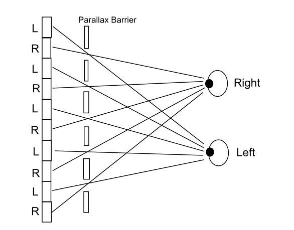
As shown in this figure, older screens used the slits to bar certain pixels from being seen by placing them above the screen. Newer screens like the one on the Nintendo DS place the barrier lower than the pixels, but before the backlight. This prevents your eyes from receiving the light from those pixels that are being shaded by the solid spaces between the slits. This results in a clearer image and a wider viewing angle.
Speaking of viewing angle, if the method works because your eyes aren’t in the same spot, it is obvious that if you move your whole head then you’ll also be seeing a different set of pixels. This is the drawback: that there is a relatively small area called the “sweet spot” that the user must position his head relative to the screen to perceive the 3D effect. It makes it inappropriate for movies, as only a portion of the seats would be in the sweet spot, but it is in use for handhelds where only one user will be viewing the screen at any given time. Another drawback is that because the slits are eliminating half the pixels from each eye, the system reduces the effective pixel count by one-half. This causes a reduction in resolution that can be countered by even higher pixel density.
Another method very similar to the parallax method is replacing the layer of slits with a series of lenses that direct light from certain pixels to a certain eye. These are called lenticular lenses and are illustrated in Figure 24-10.
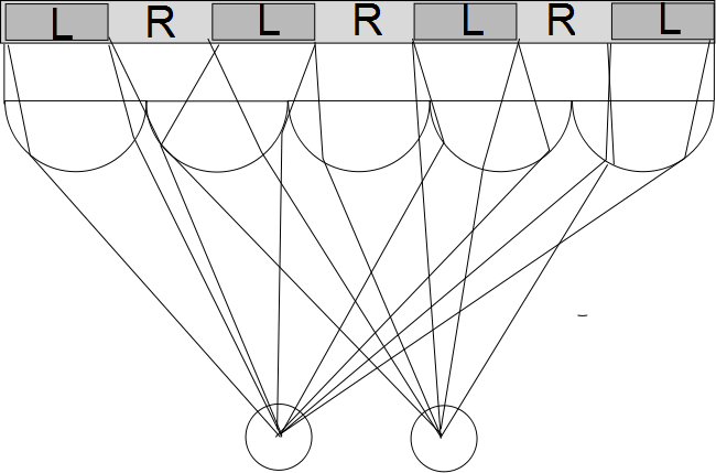
Here microscopic domed lenses are placed between the viewer and the screen. The lens focuses the light such that only certain pixels are seen by each eye, due to the slightly different angles by which the eyes view the lens. Benefits over the parallax barrier are that the position of the user is less restricted and the image is brighter. With both parallax barriers and lenticular lens arrays, it is possible to retrofit current screens with removable slide-in-place filters that allow for viewing of 3D content designed for use with those filters. At the time of writing, several large TV manufacturers are doing active research into widening the field of view of these technologies for use in a home entertainment environment.
Advanced Technologies
The displays we have discussed so far have all lacked some level of realism. For one, the eye doesn’t have to refocus to observe objects at different depths, so your brain isn’t totally fooled. Additionally, when you move around the object being projected and it doesn’t change view, you still see the object at whatever angle the object was recorded. If you were viewing the world through a window, you could walk to the right and see more of the left-handed view. However, try as you might, you can’t see around the corner of a building in a video game by moving your head at an angle of the screen. While it might be possible to recreate that effect with some sort of head tracking, there are some beyond-state-of-the-art technologies that could take this steps further.
One technology that is commonly thought of being able to produce 3D images is the holograph, a staple of science fiction. It seems like we should be able to just whip up some dynamic holographs and be done with screens all together. Who wouldn’t like to play a sports game as if it were a table-top miniature? However, due to the way they are recorded, holographs as we know them are static images. Once recorded, holographic images cannot be changed. Due to their ability to encode multiple angles of viewing, they would make wonderful display technology, and research is under way to find a material that can hold holographic data and be rewritten fast enough to induce the illusion of motion to the viewer. From time to time, you may see in the news some event incorporating computer-generated imagery displayed in what is called holographic display. These are not true holographs, but usually just a projection on a semitransparent screen. The images are still completely flat, and the illusion of 3D comes solely from the brain not registering the presence of the screen.
Another technology being actively researched is called integral photography. This is a lot like the use of a lenticular lens; however, instead of linear cylinders in an array, the lens field is more like a fly’s eye. Each lens in the array captures a complete picture from a slightly different angle. Now, when projected through a similar integral lens, the light forms a 4D field that the viewer sees as a 3D scene appropriate for his or her viewing angle. If the view moves to the side, then he or she will see a new portion of the object that wasn’t visible previously. This type of movement parallax creates very realistic 3D experiences. The advanced displays so accurately recreate the light that recorded the images that the eye can focus on different parts of the object (this is called the wave front) and therefore experience accommodation of the eyeball. Recall that this is the eighth item in our list from earlier in the chapter, and it is something the other displays are lacking. Some crude demonstrations of this technology have been presented, and it will be exciting to see how the research progresses.
Beyond any other method, the last one we’ll talk about takes the bull by the horns. If you want a 3D image, just make the image three-dimensional. The other displays we discussed all attempt to recreate 3D screens using projection from a 2D surface. There is a group of display technologies known as volumetric that dispense with any 2D elements and attempt to create a light field with well-defined x, y, and z coordinates. These displays are far enough away from consumers that the definition of a volumetric display is still being argued. One of the biggest problems with the technology will be occlusion—that is, when an object passes in front of another object, you can’t see the object behind the object that is closer to you. Pretty basic depth information, right? Well, if you are attempting to create a 3D light field, it is difficult to get the light to be blocked out when another rendered object passes in front of the original object. Simply not creating light there won’t work, as each viewer would expect the farther object to be blocked at different angles. There are some existing demonstrators that use lasers to excite electrons in the air. When the lasers are focused on the same three-dimensional point, the combined energy creates a small pocket of plasma that gives off light. These small volumes of light are often referred to as voxels and correspond to pixels in 2D display technology. The current resolution and refresh rate is not going to be wowing any gamers in the near future, but I for one can’t wait for the day I can watch the New Orleans Saints play as a three-dimensional table-top game.
Programming Considerations
Now that you have a background in how the current 3D display technologies work, there are some aspects of each that you as the programmer should consider when writing games. There are two ways to add 3D stereoscopic content to games: active stereoization and passive stereoization. These are not to be confused with the passive and active technologies for viewing the 3D images. The stereoization process is the method by which the 3D images get created in the first place.
Active stereoization is the process by which the programmer creates two cameras, rendering separate images for each eye. Passive stereoization removes the requirements for two cameras, and adds the stereoization at the GPU level. Either method is going to cost something in performance. The worst-case cost is twice a monocular scene; however, some elements of the scene, like the shadow map, will not require recalculation for each eye.
Active Stereoization
Active stereoization is conceptually simpler and offers greater control over the process of stereoization. The most naive implementation is to simply have two cameras that render complete scenes and then pass the buffers labeled one for each eye. The buffers are then swapped in and out with the traditional definition of frame rate being half the actual frame rate. However, this simple implementation duplicates some elements of the scenes that are not eye dependent.
The advantage of this technique is precise control of what each eye is seeing. This allows the programmer to determine eye separation for each frame and could be used to actually disorient the user as a game element. Consider a flash-bang grenade going off: the programmer could alter the position of the cameras such that it would disorient the user in 3D for a short period after detonation. However, this technique would cause very real discomfort to the user, so it should be not used frequently!
The disadvantages are that the programmer is now responsible for managing an extra camera that must be rendered for each frame. For commercial titles, this method can be difficult considering that most games already have to be careful about how many times they invoke the render pipeline in order to maintain playable frame rates. Having to manage two cameras creates additional runtime burden on the program and makes the use of existing game engines a little more difficult.
Also due to the fact that not everyone’s eyes have the same separation (intraocular distance) and not everyone’s brain is willing to accept fabricated binocular disparity, the program must also provide options for the user to adjust the depth and complexity of the stereo effect. If you do not provide a way for the user to tune the experience, a vocal minority will claim your game gives them a splitting headache. However, as stated before, if you are a curious amateur, the process of moving the camera and rendering stereoscopic images gives you a lot of insight into how the process works.
As discussed previously, we must take into account the intraocular distance of the viewer. This is the amount of parallax we want to give objects at infinity. This distance usually ranges between 3 cm and 6.5 cm. The large differences can arise when considering that you must consider both adults and children when creating your 3D scene. Now it is useful to develop a normalized measure of intraocular distance. Nvidia calls this real eye separation and gives the following formula for the value:
| Real eye separation = intraocular distance / real screen width |
Note that this value will change depending on the width of the user’s screen. This value is important because it is used as a reference for the maximum camera separation when rendering your stereoscopic images. Separations higher than this value will cause discomfort in the viewer. In fact, for computer screens where the user is relatively close to the screen, most people don’t feel comfortable when the camera separation is more than half the real eye separation. This is why it is a good practice to allow the user to change the separation as a parameter of the program. It is also important to remember that the separation of the cameras is also the parallax value at an infinite distance. When two images display parallax equal to separation, it is as if your eyes are perfectly parallel. This is something that happens only when you are looking at something very far away, like a mountaintop. If you increase parallax beyond separation, you would essentially be asking your viewer to diverge her eyes beyond parallel. This is sort of the opposite of crossing your eyes, and obviously is going to cause some discomfort.
As we now have an upper bound to our parallax, we can begin to create a parallax budget. Recall that the distance at which the two frustums intersect is called convergence. Well, at 100 times this distance, the value of parallax is 99% of separation. That means that for objects in the scene being rendered at that depth value, they will appear flat and all similarly far away. This is analogous to not being able to tell which peak of a faraway mountain range is the closest.
Objects between 10 and 100 times the convergence distance have parallax that varies by about 10%. This results in a subtle but perceptible depth differentiation. As you approach convergence, the parallax exponentially decreases. At the convergence distance, the parallax is equal to 0. At a distance closer to the viewer than the screen, the parallax is negative. A distance out of the screen half that of the convergence distance creates a negative parallax that is equal to the separation. If the object is any closer to the viewer, her eyes verge on crossing and eyestrain becomes a problem. Now we can draw what our budget looks like (see Figure 24-11).
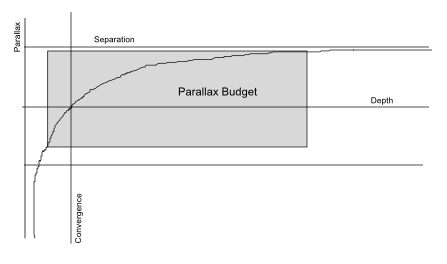
The budget scales with convergence distance and separation. You should make sure as much of the important 3D action occurs between convergence and 10 times convergence. Your entire scene should be contained with negative convergence/2 to positive 100 times convergence.
In general, you must be most careful when trying to execute an out-of-screen effect. These effects are very impressive to the viewer but cause the most eyestrain due to the rapid change in parallax. Having the object first appear farther away than the screen and then moving it closer to the user provides a context for the brain and encourages fusion. If an object is going to be closer to the user than the screen, it is also important to prevent that image from being clipped by the edge of the screen. That would make a portion of the 3D object disappear, and the clipping always occurs at the convergence point. This will give conflicting cues to the viewer and cause the 3D effect to be diminished. Given the amount of control you need in order to prevent out-of-screen effects from causing viewer discomfort, it is often best to use in non-player-controlled scenes.
Another difficult part of the game to render is the 2D elements. The user interface or other menu items that have no depth are normally rendered at convergence depth. However, there are some elements that are 2D but should be rendered at some nonzero depth. The most important of these are mouse pointers and crosshairs. These should be rendered at the depth of the object below them. This change in depth of the user-controlled pointer helps maintain the idea that the objects are at different depths.
Passive Stereoization
Passive stereoization takes the responsibility for managing the stereoization process out of the programmer’s hands. The programmer sends the render pipeline a single render command as usual, and the GPU handles generating the stereo images. Most systems rely on heuristic subroutines in the driver to take the monocular scene and generate binocular images. A heuristic subroutine is one that attempts to give a computer “common sense” about what it is trying to do to avoid having to do an exhaustive search for solutions to an existing problem. They are algorithms not based on rigid mathematical formulas but more like neural networks; they must be trained to do what you want them to. These algorithms decide which elements of the scene are eye dependent and which are not in a process that occurs entirely in the render pipeline.
It is possible for the programmer to defeat the “common sense” rules the computer is using in the pipeline so the method is not entirely fire-and-forget but does reduce a lot of the workload for development. One of the biggest benefits for larger game studios is that it avoids anyone having to reprogram existing game engines. By the same token, it allows existing games to be easily played in stereoscopic 3D. All of the preceding recommendations apply to passive stereoization except that there should be no user-adjustable settings in the game. Passive stereoization relies on third-party profiles that help the GPU do the work. The user will have set up a profile with whatever stereoization software he or she is using, such as NVIDIA’s 3D Vision. Other recommendations may be specific to the stereoizer, and manufacturers usually publish a best practices guide. The NVIDIA one is very helpful, and we recommend you read it if you are interested in using stereoization in your games.