
Chapter 23. Pressure Sensors and Load Cells
Pressure sensors are an evolution of the simple button. A simple button has two states, on or off, which can be used to trigger simple atomic actions in a video game such as firing a gun or opening a door. However, simple buttons are not capable of informing the program how you, the user, hits that button. Did you hit it quickly? Did you barely touch it at all? The only thing the program can interpret is that you did in fact hit the button.
With pressure sensors, the program has the ability to discern how the user pressed the button. This information can be used as incremental input, such as the player raising a firearm before pressing the button harder to actually fire. Additionally, pressure sensors can be used to create novel forms of human-input devices. While pressure sensitivity is not uncommon in the more traditional console gaming markets, there is also a recent push to move the sensors into touch-screen devices like the Nintendo DS and cell phone gaming market. Pressure-sensitive touch screens are currently beyond state of the art, however, so we’ll primarily discuss the traditional methods already in widespread adoption.
In addition to pressure sensors, some new gaming consoles use load cells to allow the player to use shifts in his or her body weight as input. The method by which this data is collected and how the center of gravity is determined will be discussed in this chapter. Lastly, some smartphones now include a barometer, a pressure sensor that measures the pressure of the atmosphere. What it is used for and the type of information it can provide will also be discussed.
Under Pressure
As discussed in Chapter 3, pressure is a force applied over an area. Imagine a concrete block sitting on a steel plate. The weight of the block will be evenly distributed over the area of contact, creating a pressure on the steel plate. Gas and liquid can apply pressure as well. The weight of the air pressing down on us is what is known as atmospheric pressure.
Let’s cover a quick example of how to calculate pressure just to illustrate the concepts involved. Pressure has many different units, but all of them can be equated to a force divided by an area. For this chapter we’ll stick with Newtons per square meter, as this is easiest to visualize. The SI derived unit (a unit of measure made up of other fundamental units) is called a Pascal, which is just 1 N/m2.
Example Effects of High Pressure
In Chapter 3, we discussed the concept of buoyancy and how it arises from hydrostatic pressure. Here, we’ll show the tremendous forces that hydrostatic pressure can cause on a submerged object. Let’s imagine we have a steel ball filled with normal atmospheric pressure at sea level, or about 101,000 N/m2. While this seems like a lot, your body is used to dealing with this pressure, so you don’t even notice it on a daily basis! Now we are going to take this ball and drop it into the Marianas trench, the deepest known part of the ocean. The water depth here is approximately 10,900 meters. The formula for calculating the pressure due to water (hydrostatic pressure) is:
| P(h) = ρ × g × h |
where ρ is the mass density of water, g is force due to gravity, and h is the height of the water column above the object.
Here we take the standard density for saltwater, 1025 kg/m3, and calculate what the pressure is:
| P(10,900) = (1025 kg/m3) × (9.8 m/s2) × (10,900 m) = 109,490,500 N/m2 |
Figure 23-1 shows how the pressures act against our steel ball.
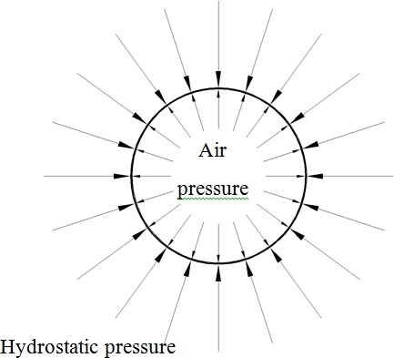
It is clear that the water pressure acting on the sphere is much larger than the air pressure we trapped inside before sinking it. Also, note that pressure always acts normal to the surface. If you happen to apply a force to the vertex of an object, you’ll have trouble modeling the right effect because a vertex does not have a well-defined normal. We can overcome this only by applying pressure to the faces of polygons or by averaging the direction of the pressure on either side of the vertex. Returning to our example, the net pressure differential on the steel ball is:
| P(water) − P(air) = 10,949,100 N/m2− 101,000 N/m2 = 10,848,100 N/m2 |
This is the pressure you would feel if 1,870 elephants were standing on a 1-square-meter plate on top of you. If our steel ball had walls that were too thin to withstand this pressure differential, it would implode. To put this all into perspective, a steel ball in space would have a pressure differential of only 1 atmosphere pushing out. It is thus much harder to design a structure to go to the bottom of the sea than it is to go to the moon. Indeed, more men have stepped foot on the lunar surface than have visited the bottom of the sea.
If the ball were open to the sea, then the pressure would act equally on each side of the steel boundary. Without a pressure differential, there would be no force to crush the ball; however, there would still be compression of the steel shell itself.
Button Mashing
While the preceding example highlights some important concepts about pressure in general, it is not usually the type of pressure used as input to a game. The most common types of pressure sensors you’ll experience in video games are pressure-sensitive buttons that indirectly measure the amount of pressure the user is exerting on the button and convert this to a relative value. Both Sony and Microsoft have incorporated pressure-sensitive (also known as analog) buttons into their controllers for the PlayStation and Xbox series of consoles.
The method by which you can detect how hard a user is pressing a button varies from very simple to very complex. We’ll focus on Sony’s method, which is very elegant. A typical push button is just two contacts separated by an insulator, most commonly air. When the button is pushed, the upper contact moves down and touches the lower contact. This completes a circuit, causing a voltage spike, which the device interprets as a button press. This is another example of a digital sensor—it is either on or off. The buttons in Sony’s controller work a bit differently. In State A in Figure 23-2, we can see that the button is not yet pressed and an air gap exists between the solid conductor and the domed flexible conductor. In State B the button is depressed with minimal pressure, and the dome just barely makes contact. The button is now activated. If the user continues to press down harder on the button, the dome deflects and increases the area of contact with the fixed conductor; the larger the contact area, the greater the conductivity of the connection. This causes a rise in the current flowing in the circuit.
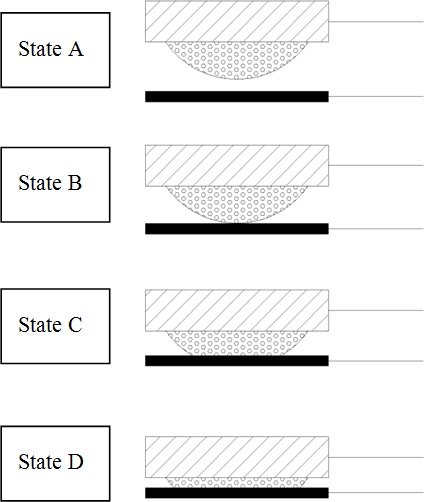
By measuring this increase in current, the controller knows how far down the button is being pressed. In State D in Figure 23-2, the button is at its limit of travel and the dome has deflected to its maximum contact area. The difference between this maximum and the minimum required to detect contact determines the absolute lowest and highest pressure the button is able to differentiate. For instance, let us assume that if the button were depressed completely, the current would register at Imax. If the button were not pressed at all, of course, the current would be 0. If we call the current I(t) for any time, t, we see that the ratio I(t)/Imax gives a nondimensional quantity for how far down the button is pressed. During this operation, the hardware converts the analog voltage to a digital representation suitable for input to a program. For the Sony example, this value is calculated by the hardware and passed as part of the data stream from the controller with hex values between 0x00 to 0xFF, or in other words, integers 0 to 255 in decimal. This means that each button’s travel is divided into 255 parts that your program can register.
While 255 individual increments are beyond the human ability to control fingertip pressure, different ranges of pressure have practical uses in games. For example, you could program your button to raise a weapon with a half-press (0 to 127), bring the weapon to the shoulder with more pressure (127 to 250), and to fire when totally depressed (250 to 255). Of course, those values would have to be tuned for the desired level of sensitivity. Another example would be to control the throttle on a car by using the values of 0 to 255 as thrust multipliers.
Another use of knowing a button’s position would be tracking it over time. With a time history of position, you can differentiate to get velocity and again to get acceleration. This would allow the program to differentiate between a button that is either slowly depressed or quickly depressed. Most hardware doesn’t help you here, so you’ll have to store the values and calculate the velocities in whatever increments are appropriate for your program. As real-time velocity sensing might be taxing to the user as real-time input, the best use would be as input to something that the user doesn’t have to control constantly. Imagine having to keep a button pressed down at the correct pressure for your gameplay for longer than a few minutes; I can feel my wrist cramping now. However, the pressure button is useful for many inputs. For example, how far a button is pressed down might be used to draw back the head of a putter, while the speed at which the button is released could be used to determine the speed at which the putter is brought back to the ball.
Load Cells
Beyond simple buttons, there are other novel ways to use pressure sensors to allow a user to interact with your games. For example, Nintendo’s Wii uses a balance board peripheral based on load cells to detect a person’s stance.
Note
The original idea for the Nintendo balance board came to video game designer Shigeru Miyamoto after he was inspired by watching sumo wrestlers weigh themselves with each leg on a different scale. They are too heavy to use one scale!
Tiny scales
Load cells work differently than the pressure-sensitive buttons described previously, but like pressure-sensitive buttons, they come in different types, all of which measure the load pressing on them. The most common way, and the one used in the Nintendo balance board we’ll discuss shortly, is through what is called a strain gauge.
A strain gauge, as you might be able to guess, does not measure force directly but instead measures how much strain the gauge is experiencing. Strain is a measure of how much a rigid body has deformed independent of its rigid-body motion. While there are several notions of strain in continuum mechanics, the one we are concerned with here is often referred to as engineering strain. This type of strain quantifies how much a structural element has deformed compared to its original, or rest, length. We normalize this by dividing the change in length over the rest length. By testing the material, one can develop a stress versus strain curve that relates how much stress it takes to cause a certain amount of strain. Once the pressure that causes an amount of strain is known, it is possible to determine the amount of load. Now you might be wondering how the strain gauge measures the amount that the Wii’s legs compress when you stand on them.
One of the most common electronic strain gauges is the piezoresistive strain gauge. The simplest example of a piezoresistive strain gauge would be a single wire. If you were to elongate a wire from its rest length, the cross-sectional area decreases. This causes a rise in the electrical resistance of the wire. After measuring the rest resistance, you can use the difference to determine how much the wire has elongated. Knowing the mechanical properties of the wire, you can also determine how much force it takes to stretch the wire.
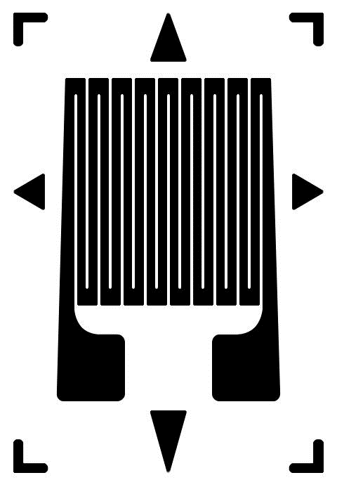
To make strain gauges sensitive without having long linear wire elements, the conductive material is often arranged in a strain-sensitive pattern, as shown in Figure 23-3. This looping back and forth of the conductor allows for great sensitivity without increasing the physical space the sensor occupies. Here the rest length would be 18 times longer than the physical length of the sensor.
Center of gravity
The board has four legs, each of which houses a load sensor. The board uses strain gauges similar to those discussed earlier. These gauges elongate when a force is applied to them. The elongation changes the electrical resistance of the circuit of which the strips are a part, and this is reported back to the controller. Figure 23-4 shows two sensor outputs. The first is with the user standing so that her center of gravity is over the center of the board. The second state shows what the board’s sensors would measure after the user has shifted her center of gravity.
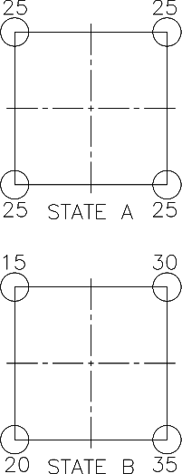
It is easy to intuitively recognize that the center of gravity must be over the center of the board in State A and toward the lower-right corner in State B. However, to get the exact location of the center of gravity in State B, we’ll have to do a little more work. First things first: we have to define a coordinate system. This is shown in Figure 23-5.
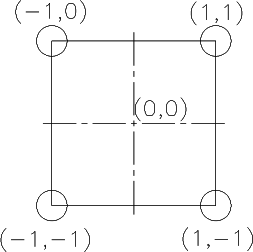
This coordinate system is arbitrary. If the board isn’t a perfect square, such as with the Wii board, then the coordinates of the load cells must be changed accordingly. Now that we have defined the location of the center of the board and the position of the load cells, we can use a weighted average to compute the location of the user’s center of gravity. The weight that we give each value will depend on how much of the user’s weight is on each of the four corners. That weight will “pull” the center of gravity toward the location of the load cells as defined in our coordinate system. How much each load cell mathematically pulls the center of gravity will be based on the weight supported at that location. This is most easily determined via two tables, one for the x coordinate (Table 23-1) and one for the y coordinate (Table 23-2).
Load cell | Weight | Arm | Weight × Arm |
(1,1) | 30 | 1 | 30 |
(−1,1) | 15 | −1 | −15 |
(−1,−1) | 20 | −1 | −20 |
(1,−1) | 35 | 1 | 35 |
Total: | 100 | 30 | |
Average: | 30/100 = 0.30 |
Table 23-1 takes the weight in each corner and multiplies that value by the value of its x coordinate. This is equivalent to a moment. Taking the sum of those moments (30) and dividing by the total weight gives the average value of 0.30, or .3 units to the right in our coordinate system. The y-axis is treated similarly.
Load cell | Weight | Arm | Weight × Arm |
(1,1) | 30 | 1 | 30 |
(−1,1) | 15 | 1 | 15 |
(−1,−1) | 20 | −1 | −20 |
(1,−1) | 35 | −1 | −35 |
Total: | 100 | −10 | |
Average: | −10/100 = −0.10 |
Using a similar weighted average as shown in Table 23-2, we see that the user’s center of gravity is −0.10, or 0.1 units behind the center. If we were using this to control an onscreen sprite, we could define a 2D direction vector based on this information.
In addition to just determining the center of gravity, you can use this information to make educated guesses on what else the user is doing to cause the load distributions. After computing the center of gravity, the Wii uses what Nintendo calls a motion-identifying condition table to guess what movements the user is making. The table correlates the ratio of the sum of the load values to the body weight of the user and the position of the center of gravity to determine body orientation. For example, the Wii can tell if both of the user’s feet are on the board, or if the user is accelerating part of his leg. The table provided in the Wii patent is reproduced in Table 23-3.
Motion | Ratio of load value to body weight value | Position of the center of gravity |
Right foot riding | 25 to 75% | +0.01 to +1.0 |
Both feet riding | More than 95% | −0.7 to +0.7 |
Left foot riding | 25 to 75% | −1.0 to −0.01 |
Left thigh lifting | More than 100% | +0.01 to +1.0 |
Right thigh lifting | More than 100% | −1.0 to −0.01 |
Less than 5% | Not considered |
Barometers
Continuing our exploration of new user input methods, especially in the rapidly maturing mobile device gaming market, now we’ll discuss an interesting inclusion in the latest smartphones: a barometer. Unlike buttons and balance boards, whose pressure sensors only indirectly handle pressure, barometers directly measure the fluid pressure that the atmosphere exerts on the sensor.
The sensors used in mobile phones today are piezoresistive microelectromechanical systems (MEMS) and are very accurate. As shown in Figure 23-6, the sensors consist of a void machined into a piece of silicon. The diaphragm is then bonded to a stiff material such as steel or glass. As we are trying to measure absolute pressure, this bond is airtight. Using a material called monocrystalline semiconductor silicon to form the void ensures that the entire diaphragm acts much like a piezoresistive strain gauge.
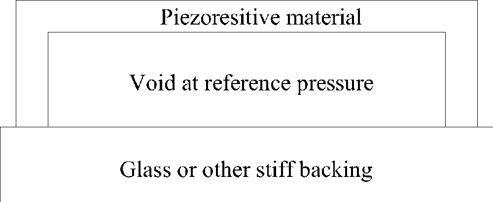
Now we have a situation similar to the steel ball in the ocean, only this time it is a tiny silicon ball in the ocean of air surrounding the earth. When the sensor is moved deeper or shallower in the atmospheric ocean, the pressure on the outside of the diaphragm changes. This causes the pressure differential to change and a force to be exerted on the silicon diaphragm. This force causes a deflection that changes the resistance of the piezoresistive material and can therefore be measured by the sensor. This part will be taken care of by the hardware and the encoded value sent to the operating system.
To give you an example, in the Android operating system, the API has a public method,
getAltitude(float p0, float p), to determine altitude, in meters, between the sensor pressure and the pressure at sea level. It usually
reads the current atmospheric pressure, p, from the sensor by
listening to sensor manager callback interface method abstract void
onSensorChanged(SensorEvent event). Here the class event holds the sensor values, the accuracy of those values, a reference to the
sensor itself, and a timestamp for when the event occurred. The pressure is reported in hectoPascals (hPa) or 100 N/m2. The
sea-level pressure, p0, that this is compared to is either
obtained from an online database or is set at the constant SensorManager.PRESSURE_STANDARD_ATMOSPHERE. As pressure at sea level changes with
different weather conditions, we obtain higher accuracy by retrieving it from a nearby airport
or other weather station via the Internet. To get the change in altitude between two points,
you must repeat this process twice as follows:
float altitude_difference =
getAltitude(SensorManager.PRESSURE_STANDARD_ATMOSPHERE,
     pressure_at_point2) -
getAltitude(SensorManager.PRESSURE_STANDARD_ATMOSPHERE,
     pressure_at_point1);
At first it may seem strange for your cell phone to have a barometer in it; however, the barometer’s ability to detect the air pressure allows you to make a good guess on your altitude. As shown in Chapter 22, in order to determine your position via GPS you have to solve a four-dimensional set of linear equations. The time required to solve these equations can be dramatically decreased if you know approximately where you are to begin with. Currently, the position of which cell phone tower your phone is connected to is used as a starting point. Using a barometer allows the device to guess its altitude to further reduce the time to obtain a GPS fix.
While the sensor was included for a specific purpose, it can also be adapted as an input device. For instance, the Bosch BMP180 currently being included in devices is accurate to plus or minus one meter. In fact, Google Maps now provides indoor directions, including knowing what floor you are on in airports and shopping malls. This functionality could be used to aid in the location-based gaming discussed in Chapter 22 by giving it greater resolution in the vertical dimension. It could also be used to determine if the user is holding the phone near her feet or her head, further augmenting the orientation sensing discussed in Chapter 21. Of course, it can also be used to help weather forecasting and allow you to have real-life changes in pressure affect in-game events.