
Chapter 20. Touch Screens
It is hard to deny that we are currently moving toward a post-PC computing environment. The proliferation of smartphones, tablets, and other mobile computing platforms will have far-reaching implications for how people interact with computers. These form factors do not allow for the more traditional mouse and keyboard of input for games and therefore rely heavily on the use of touch screens. This chapter aims to give you some background on the different types of touch screens, how they work, and their technical limitations. Note that we will extend our particle simulator to work with the iPhone’s capacitive touch screen; the final product is very similar to the mouse-driven version but provides a starting point for a touch-driven physics simulator.
While this chapter will primarily deal with the most two most common types of touch-sensitive screens, resistive and capacitive, the following section gives an overview of many different types. In the future we may see a move to more exotic devices, especially for large-format computing devices.
Types of Touch Screens
Resistive
Resistive touch screens are basically a giant network of tiny buttons. Some of them have 4,096 × 4,096 buttons in a single square inch! OK, so they are not quite just normal buttons, but they come close. Resistive touch screens have at least two layers of conductors with an air gap between them. As you press on the screen, you close the gap. Bam, circuit complete, button pressed. We will flesh out that simplified description shortly.
Capacitive
Also a topic we’ll soon discuss in detail, capacitive touch screens are very common on today’s smartphones. These touch screens operate by calculating the change in electrical capacitance at the four corners of the screen when your finger influences the capacitive nature of the circuits under the glass. The limitation is that whatever touches the screen must be electrically conductive. If you insulate your fingers with gloves, the screen will no longer be able to locate your touch. However, this can be solved with a few stitches of conductive thread.
Infrared and Optical Imaging
Infrared touch screens use arrays of infrared LED and photodetectors to detect and interpret an object breaking the path of a LED-photodetector pair. This uses line-scanning techniques and is a very robust design.
Optical imaging techniques are relative newcomers to the touch screen scene whose big advantage is that they are extremely scalable. They use imaging devices and light sources to detect where the screen is being touched by interpreting any shadows cast by an object through the thickness of the material.
Exotic: Dispersive Signal and Surface Acoustic Wave
Several other exotic touch screen technologies exist. We won’t get into detail here, but 3M has a system that detects mechanical energy in glass caused by a touch. The amount of vibration energy that reaches each sensor determines the position.
Another example of exotic screen input, surface acoustic wave technology detects changes in the pattern of ultrasonic waves traveling along the surface of the screen.
Step-by-Step Physics
Resistive Touch Screens
Resistive touch screens are classified as a passive touch screen technology because the screen registers a touch without any active participation by the object touching the screen. This is their major benefit over active technologies, such as capacitive touch screens, as resistive screens can be activated by nonconductive objects like a pen or gloved finger. In the past, resistive screens were limited to a single input, and that’s the type we’ll describe, but they can be made to work with two or more simultaneous inputs, also known as multitouch.
One-dimensional resistive touch sensor
To ease ourselves into this discussion, we will begin by looking at a one-dimensional touch screen. Let’s imagine we have built the machine described in Figure 20-1.
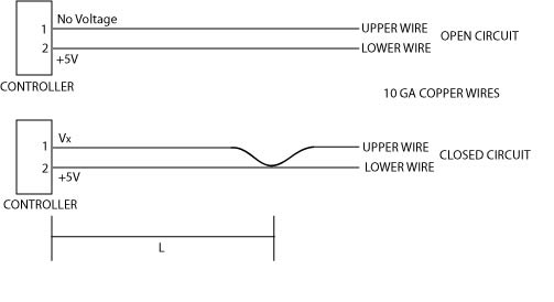
As you can see, our sensor has two states, an open circuit state and a closed circuit state. In the open circuit state, the controller is supplying a 5V signal to pin 2 and waiting for any return voltage on pin 1. With no touch to bring the wires together, the circuit is open. No voltage is present at pin 1, and therefore no touch is sensed. When the wires are touched, they are brought together and the circuit is closed. A voltage will then be present at pin 1. A touch event is registered.
This type of sensor, which looks only for the presence or absence of voltage without regard to its value, is called a digital sensor. It can detect only two states: on or off (1 or 0, respectively). OK, so it’s not quite a touch screen yet; essentially at this point all we have is a simple button. Moving forward, let’s say that we not only want to trigger an event when we press our button, but we also want to simultaneously input a value based on the location along the wire, L, that we pressed.
To accomplish this, the controller patiently waits for a voltage at pin 1. When it senses a voltage, that digital “on” switch causes the controller to then probe the voltage that is present, which we have labeled VX. Now we get to the reason it is called a resistive touch sensor. Current, voltage, and resistance are all interrelated by Ohm’s law. This physical relationship is expressed as:
| V = IR |
Where V is voltage, I is current, and R is resistance. The exact physical meaning of each of these is less important right now than how they are related, so don’t get too worried if you can’t recall their definitions. In the case of our circuit, I, or current, is going to be constant. As the controller measures the voltage, V, at pin 1, we can now solve for resistance:
| R = V/I |
With our constant current, I, and our known voltage, VX, we can calculate the resistance of the circuit by inputting (5 – VX) for V as follows:
| R = (5 – VX) / I (1) |
Note that we have to have the change in voltage across our resistor (the wire), so be sure to use the difference between the two values. Every conductor has an inherent internal resistance, and through testing we can determine what the resistance is, measured in ohms per unit length, and use that to determine our total resistance described by:
| R = 2rL |
where r is the aforementioned ohms per unit length and R is the total resistance of our circuit. Note that we have multiplied L by 2 to account for both the wire run to the point of contact and back. If we substitute this for R in our earlier equation, we now have:
| 2rL = (5 – VX) / I |
And finally:
| L = (5 – VX) / (2rI) |
where L is the only unknown. To illustrate, let us assume the measured voltage is 4.95V and the wires are 24-gauge copper wires. A quick look in a standard electrical engineering book gives the resistance as 0.08422 ohms per meter. When we designed our constant current source, let’s say we picked 50 milliamps:
| L = (5 – 4.95V) / ((2)(.08422 ohms/meter)(.05A)) |
| L = 5.9 meters from the controller |
As you can see, the material’s resistance per meter, the constant current supplied, and the sensitivity of the voltage-sensing circuit must all be finely tuned to ensure that the controller is capable of sensing touch events in the appropriate dimensions. In a resistive touch screen, the wires are microscopic so that the resistance per meter is much higher. This allows the screen to detect smaller distances.
Four-wire resistive touch screen
With some modification, we can expand our previous model to two dimensions. In the four-wire touch screen, there are four basic layers and four wires, three of which will be used at any given time. The general layout is given in Figure 20-2. The squares containing the X and Y wires would actually be overlapped but are shown skewed here for clarity.
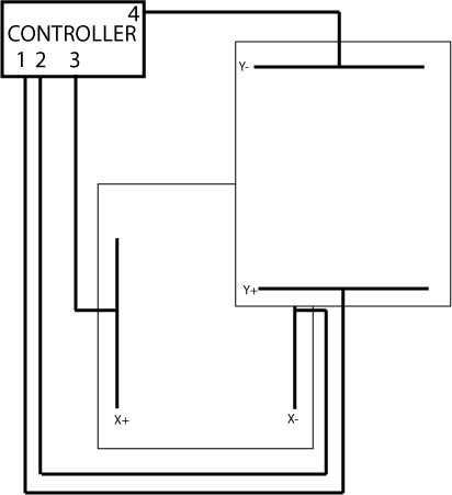
The reason for calling it a four-wire touch screen should now be obvious; however, remember that only three of the wires will be active at any time. The basic structure is shown in Figure 20-3.
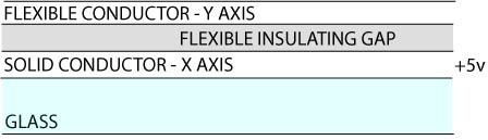
The first layer of the screen comprises a flexible conductor separated by an insulating gap. Under the gap lies a solid conductor. When a finger presses down on the outer layer of flexible conductor, it crosses the gap and makes contact with the solid conductor. The conductors are thin layers of indium-tin oxide (ITO) with silver bus bars on either end of the sheet, shown as black lines in Figure 20-2.
To condense the description of its operation, we’ve outlined the three possible states in Table 20-1.
Activity | Pin 1 | Pin 2 | Pin 3 | Pin 4 |
Waiting for touch detection | Open | Open | Digital input [pull up] | Ground |
Read X position | Voltage probe | Ground | Voltage source | Open |
Read Y position | Voltage source | Open | Voltage probe | Ground |
Voltage probe means the chip is sensing the voltage on that pin, voltage source is the pin supplying a voltage to ground, and open means it is unused. The sequence of a touch event begins with pin 1 and pin 2 open. Pin 3 is configured to digital input with pullup signifying a voltage is supplied to the pin. When a finger presses on the outer layer and makes contact with the lower layer, pin 3 goes to ground. When the controller senses the voltage fall on pin 3, it moves to the second row and reads the X position.
To read the X position, the lower layer is energized from pin 3 to pin 2. The voltage source creates a gradient along the layer. Pin 1, connected to the upper layer, delivers a voltage to the controller when a touch pushes it down to make contact with the lower energized layer. The value of this voltage depends on where the contact is made in the gradient, much like the previous linear example. Once the X position is known, the controller moves to the next row and reads the Y position.
The method of obtaining the Y position is much the same but in reverse. The voltage supply is switched to pin 1, which develops a voltage gradient with pin 4. Then pin 3 is probed and the voltage corresponds to the distance along the voltage gradient. As the controller is capable of repeating the detect, read X, and read Y cycles approximately 500 times a second, the user is not aware that the screen doesn’t actually register the X and Y coordinates at the same time.
While the four-wire resistive touch screen is the simplest two-dimensional touch sensor, there are issues with durability. The main drawback of this type of touch screen is that, because the layers must be separated by an insulating gap, at least one of the layers must be flexible. In the four-wire type, the constant flexing of the first conductive layer introduces microcracks in the coating, which lead to nonlinearities and reduce the accuracy. Other models of resistive touch screens overcome this issue with additional layers that remove the need for the flexible conductor. They have also been adapted to provide multitouch capability. We will discuss multitouch and how it works with capacitive touch screens in greater detail shortly.
Capacitive Touch Screens
A capacitive screen uses a piece of glass coated in a transparent conductor. When your finger or other conductor comes into contact with the screen, the electrostatic field is disturbed, causing a change in the capacitance. To understand how capacitive screens work, let’s quickly review capacitance in general.
A capacitor in its simplest form is two conductors, usually thin plates, separated by an insulator. If you apply a voltage across the two conductors, a current will flow and charge will build up. Once the voltage across the plates is equal to the supply voltage, the current will stop. The amount of charge built up in the plates is what we measure as the capacitance. Previously, we noted that one issue with resistive screens is that one part must always flex to close a insulating gap and complete a circuit. This repetitive action eventually leads to mechanical failure. A capacitor can be dynamically formed by any two conductors separated by an insulator. Noting that glass is a good insulator, it is easy to see that a finger separated from a conductor by glass can change the capacitance of a system. In this way, the finger or stylus doesn’t have to cause any mechanical action, yet it can still effect changes to the sensors, which are then used to measure the location of the touch.
The methods of determining location based on capacitance on mobile devices are self-capacitance and mutual capacitance.
Self-capacitance
Anyone who has lived in a dry winter has felt the shock of a static electricity discharge. This zap is possible because the human body is a pretty good capacitor with a capacitance of about 22 pico-farads. This property is known as body capacitance. Self-capacitance screens take advantage of a physical property defined by the amount of electrical charge that must be added to an isolated conductor to raise its potential by one volt. When the fingers act as a conductor of the body’s inherent capacitance, the sensors on the other side of the glass experience a rise in electric potential. Given that the sensors are on the other side of a good insulator, glass, there won’t actually be any discharge of energy, unlike when you touch your metal car door and get “zapped.” Self-capacitance in this manner produces a very strong signal but lacks the ability to accurately resolve multiple touches. Therefore, it is often used in conjunction with the next type of touch screen we’ll discuss, mutual capacitance.
Mutual capacitance
The other form of capacitance-sensing screen, mutual capacitance, is formed by a grid of independent capacitors. A probing charge is sent over the rows or columns. As the capacitors charge and discharge, the system can sense the capacitance of each individual capacitor. As just discussed, the body is a good capacitor, and bringing part of it close to the capacitor grid changes the local electric field. Those capacitors that are under a finger or other conductor will read lower values than normal. Each capacitor can be scanned independently, enabling high resolution of where the touch event is occurring. Additionally, because they act independently of one another, it is possible to accurately register multiple touches. Think of this system as taking a picture of the capacitance on the skin of the screen. Using algorithms similar to image processing and edge detection, this system can compute the extent of a touch event.
Example Program
Included in the source code accompanying this book is an example of the particle explosion program from Chapter 8 that uses touch screen input instead of a mouse click.
The code for a Cocoa touch Objective-C event is as follows:
- (void)touchesBegan:(NSSet *)touches withEvent:(UIEvent *)event
{
    UITouch* touch = [[event touchesForView:self] anyObject];
    firstTouch = [touch locationInView:self];
    self.status = YES;
    [self trigger];
}
where firstTouch is defined by
CGPoint firstTouch; in the header file.
The CGPoint is a Cocoa touch object
capable of storing an (x,y)
coordinate in the display view’s coordinate system. We can then use
firstTouch.x and firstTouch.y later in our program to give a
location to the particle explosion.
As you can see, it is very similar to a mouse-based event. One big difference is that you could adapt the code to handle multitouch events. Computers recognize only one mouse cursor at a time, but with a touch screen you can register multiple clicks simultaneously.
Multitouch
In iOS you must first enable delivery of multiple touch events by
setting the multipleTouchEnabled
property of your view to YES; the
default is NO. Next you must create a
class to keep track of multiple TParticleExplosion structures. Then it is as
simple as polling the position of the start points of multiple touches
to trigger multiple explosions. The Objective C code to store the start
points of multiple touch events would look like:
- (void)storeTouchPoints:(NSSet *)touches{
    if ([touches count] > 0) {
        for (UITouch *touch in touches) {
            CGPoint *point = (CGPoint
            *)CFDictionaryGetValue(touchBeginPoints, touch);
            if (point == NULL) {
                point = (CGPoint *)malloc(sizeof(CGPoint));
                CFDictionarySetValue(touchBeginPoints, touch, point);
            }
            *point = [touch locationInView:view.superview];
        }
    }
where CFDictionaryRef is an
immutable dictionary object that allows the copying of the object and
its key value. One last consideration for this example is that as you
are now creating multiple physics simulations simultaneously, you may
have to decrease the frequency of the time steps to allow the animations
to proceed smoothly. Multitouch can become programmatically complex, but
the physics are pretty simple. The event-handling guide for your
particular development language should give detailed guidance on
handling the event chain.
Other Considerations
One of the major advantages of touch screens is that their layout and actions are entirely software based. That is to say, if a certain button does not pertain to the current layout, it can be discarded and the freed space used for additional relevant controls. We will discuss other less obvious considerations in the following sections.
Haptic Feedback
The flip side of the advantage of not being locked into a set of physical buttons is that the user must rely almost entirely on vision to interact with the controls. At least one of the authors of this book uses a keyboard with no letters on it at all, instead relying totally on the physical position of the keys to determine which key to strike. This would be much harder without the tactile and audio cues to signify that the correct key has been pressed. Indeed, it is easy to tell when he is typing poorly because the backspace key is much louder than the rest!
The method of including physical feedback to assist a user in interaction with entirely virtual objects is known as haptic feedback. The first use of haptic feedback in games was limited to arcade games such as Motocross, in which the handlebars shook after an in-game impact. It is now considered standard on video game controllers, which vibrate to inform the user of some event.
In the realm of touch screens, haptic feedback is used to inform the user of a successful key strike or other touch-based event. Some touch screens even incorporate some movement of the entire screen when pressed. This feedback still doesn’t allow touch typing, as it only dynamically responds and provides no static tactile feedback for different buttons.
Modeling Touch Screens in Games
Given their planar nature and the lack of inherent haptic feedback, touch screens can be an easy way to implement controls with which a character in a game can interact. The amount of physical modeling required to create a realistic in-game keyboard is pretty intense. Thus, there are very few examples of an in-game character having to sit down and type a code in to a terminal via a standard keyboard.
By using touch screens for in-play control of objects, you can avoid an additional physical model while retaining realism. It would also be interesting to see games use realistic touch screen interfaces so that a character would have to remove his gloves to use a capacitive screen. Lastly, the exotic screen technologies mentioned earlier provide many creative avenues of modeling those types of screens in games. For example, for screens measuring sound waves in the glass or other mechanical energy, low-grade explosions could be used to trigger these in-game input devices.
Difference from Mouse-Based Input
One important consideration for game developers in regards to touch screens is the difference from traditional mouse- and keyboard-based gaming. As console game developers have long been aware, it is hard to compete with the speed and accuracy of the mouse/keyboard combination. Many first-person shooters segregate their online gaming between controllers and mouse/keyboard setups, as the accuracy and speed of the mouse gives those players an unfair advantage. Upon using touch screens on many different gaming devices and mobile computing platforms, we feel that this advantage is even more pronounced.
A touch by a finger is an elliptical shape whose contact patch depends on the specific finger being used, the pressure applied, and the orientation of the finger. The user generally perceives the point of touch to be below where the actual center of contact is, so adjustments must be made. This is generally all handled automatically by the operating system so that a single touch point is computed and handed to the game via an API. However, this generic approach to computing touches must obviously sacrifice accuracy for universality so that it is not calibrated for one specific user.
Another inherent drawback to touch screens is the need to touch the screen. This means a large portion of your hand will be blocking the screen when you are controlling that element. One can imagine that in a first-person shooter, this would be a great disadvantage over someone who is playing with a keyboard and mouse.
Lastly, mouseover is not available to touch-screen-based input. Consider a game where you would trigger actions by merely moving a mouse cursor over an object. These actions could be distinct from clicking on the same object. However, with touch-screen-based input, that object would be obscured by whatever is triggering the screen, therefore rendering the mouseover action invisible to the user.
Custom Gestures
As a last note, another possibility for touch input to a game is the use of custom gestures. These allow the user to draw a shape on the screen that the program recognizes as a gesture. It can then execute arbitrary code based on that input. As this is more pattern recognition then physics, we won’t cover it here, but we can recommend the book Designing Gestural Interfaces by Dan Saffer (O’Reilly) as a detailed look at this subject.