
C H A P T E R 3
Robot Engineering Requirements: Controlling Motion
Well, you have finally made it to the good stuff. In this chapter, we will be discussing motor control, a very important part of robotic design that will be used throughout this book. Motor control allows us to give a robot life, but we will not simply be pushing a button to control out robot. Instead, per a hypothetical customer's request, we will be controlling the motor speed and direction through serial communication.
We can accomplish this using an H-bridge and a hex inverter. The H-bridge will be used to drive two motors and the hex inverter will be used to convert a signal from 0 to 1 (1 to 0). The company wants each of the comma-separated parameters to go to these specific pins. Another requirement the company has is that the final prototype needs to be configured on a chassis—but not until the hardware and software have been tested.
To get the most out of this project, you will need a basic understanding of the engineering process and the Arduino programming language as discussed in the first two chapters. If you have not read them yet, please do so before proceeding. Before tackling our client's request, though, you'll need some fundamental information to give you the necessary foundation to create the final project. To start things off, we'll discuss the H-bridge and its various uses followed by a review of the hardware that will be used in this chapter. We will then create four small projects that will teach you how to turn on and off a motor with a button. Next, you'll learn how to use a potentiometer to control the speed on a motor. After that, you'll learn how to control multiple motors with the H-bridge and how to control both speed and direction with a potentiometer and a switch. Armed with your newfound knowledge, you'll create a robot that uses the H-bridge to control its movements.
Hardware Explained: The H-bridge
H-bridges are very useful integrated circuits (ICs); they allow for higher voltages to be connected to motors without using the Arduino's weak 5V supply. With some H-bridges, you can use up to 30V. Figure 3-1 shows three examples of an H-bridge; for this chapter, we will be using the motor shield from SparkFun shown on the far right.
![]() Note For all of the shields that we use in this book, you will need to buy not only the shield itself but also two 6-pin female headers and two 8-pin female headers.
Note For all of the shields that we use in this book, you will need to buy not only the shield itself but also two 6-pin female headers and two 8-pin female headers.
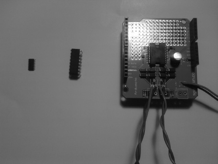
Figure 3-1. A few H-bridges (from left to right: surface mount H-bridge, through hole H-bridge, and motor shield from SparkFun)
The SparkFun motor shield has two motor ports, port A and port B; these ports correspond to four pins on the motor shield from SparkFun. They are digital pin 3: PWMA, which controls the speed of motor A, digital pin 12: DIRA, which controls the direction of motor A, digital pin 11: PWMB, which controls the speed of motor A, and digital pin 13: DIRB, which controls the direction of motor B. We will be using an H-bridge to control the speed and direction of motors. The motor shield from SparkFun has a built-in L298P H-bridge, which can handle up to 18V and uses digital pins 3, 11, 12, and 13 to control speed and direction. You can also use a stand-alone H-bridge such as the L293D, which has an input voltage of up to 37V. In this chapter, we will use the motor driver to control motors with a potentiometer and a switch, control speed, and control direction among other things.
Gathering the Hardware for this Chapter
We will be using the Dagu 2WD Beginner Robot Chassis V2 from Robotshop.com. Later in this chapter, the requirements document presented will have a specification for this chassis. This piece of hardware is going to be used to hold the circuitry, such as the Arduino and motor shield. You can find this chassis at www.robotshop.com/dagu-2wd-beginner-robot-chassis-v2-2.html.
I chose this chassis for its two-wheel design and the generous space on which it has to prototype. If you already have a chassis or you want to buy a different one, just make sure it is a two-wheel-drive chassis, as we will be using the two-wheel system throughout the rest of this book.
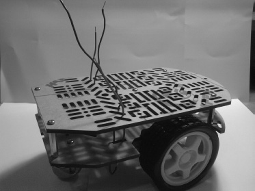
Figure 3-2. In this chapter, we will use Dagu 2WD Beginner Robot Chassis V2.
Understanding the Basics of Motor Control
In this section, we will be discussing the basics of motor control in four separate projects: turning on a motor with a button, controlling the speed of a motor with a potentiometer, controlling multiple motors with the Arduino, and finally, controlling speed and direction. These will form the foundation we use to build our project when we get the requirements document for a robot later in this chapter.
![]() Note For this section, we will be using a solderless breadboard instead of a chassis (we use the chassis only for the last project in this chapter).
Note For this section, we will be using a solderless breadboard instead of a chassis (we use the chassis only for the last project in this chapter).
Project 3-1: Turning on a Motor with a Switch
This project will mostly focus on the digital pins and will use an H-bridge so we can use higher voltages to run the motors with the Arduino. Project 3-1 will allow us to turn on a motor on that moves in a clockwise direction.
Gathering the Hardware
Figure 3-3 shows the hardware for this project, minus the 9V battery, 9V connector, and solderless breadboard:
- Arduino Duemilanove (or UNO)
- Motor shield from SparkFun
- On/off switch
- 6V motor
- Solderless bread board
- 9V battery
- 9V battery connector
- Two terminal blocks from SparkFun
- Extra wire
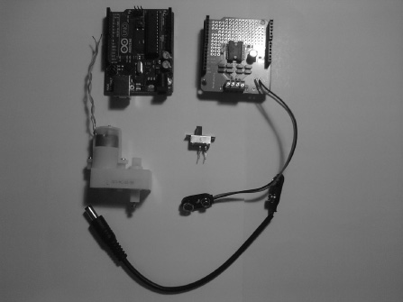
Figure 3-3. Hardware for this project
Configuring the Hardware
First, solder the female headers onto the motor shield and connect the motor shield to the female headers on the Arduino Duemilanove. Next, connect the A terminal on the motor shield to the 6V motor by soldering a terminal block to the motor shield and connecting your motor to that terminal block (Figure 3-4 shows this configuration). Finally, connect your on/off switch from ground to digital pin 10 on the Arduino, as Figure 3-5 shows. Figures 3-6 and 3-7 illustrate the hardware configuration for this project.
![]() Note Both the 9V battery and the computer should be connected to get the best results, or you can hook a 9V battery to the power of the motor shield and the Arduino.
Note Both the 9V battery and the computer should be connected to get the best results, or you can hook a 9V battery to the power of the motor shield and the Arduino.
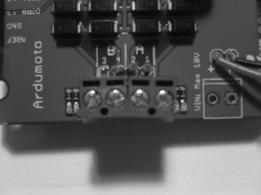
Figure 3-4. Terminal blocks added to the motor shield
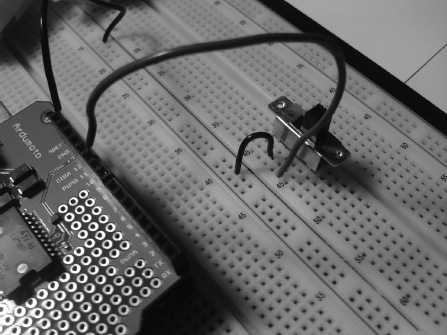
Figure 3-5. The switch is connected to digital pin 10 and ground on the Arduino.
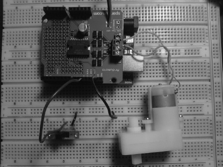
Figure 3-6. The motor is connected to the motor port A on the motor shield, and the switch is connected to digital pin 10 and ground on the Arduino.
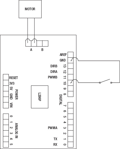
Figure 3-7. The schematic for this project
Now that you have connected the push button and motor, you need to connect your Arduino to your computer so that the software can be uploaded to the Arduino. We will write the program for this project in the next section.
Writing the Software
The software for this project will resemble the Blinking LED project that we created in Chapter 1. It will have a digital input, a digital output, and a conditional statement controlling that output. Listing 3-1 provides the code for this project.
Listing 3-1. Turning on a Motor
const int buttonPin = 10; // Sets buttonPin to digital pin 10

const int motorPin = 3; // Sets motorPin to digital pin 3
int buttonVal = 0; // Will pass button value here
void setup()
{
pinMode(buttonPin, INPUT); // Makes buttonPin an input
pinMode(motorPin, OUTPUT); // Makes motorPin an output
digitalWrite(buttonPin, HIGH); // Activates the pull up resistor
// If we did not have this, the switch
// would not work correctly.
}
void loop()
{
buttonVal = digitalRead(buttonPin); // Whatever is at buttonPin is
// sent to buttonVal
if (buttonVal == 1)
{
digitalWrite(motorPin, HIGH); // Turn motor on if buttonVal equals one
}
else
{
digitalWrite(motorPin, LOW); // Turns motor off for all other values
}
}
This code first initializes buttonPin to pin 10, motorPin to pin 3, and buttonVal to 0 (not pin 0, just the integer value 0). Next in the setup structure, buttonPin is made an input; motorPin is made an output, and most importantly, we activate pin 10's pull-up resistor; this is an onboard resistor that can be called in the software by using a digitalWrite() function. For example, putting digitalWrite(10, HIGH) inside the setup structure activates pin 10's pull-up resistor (we could use an external resistor instead, but this way is easier). Finally, when we get inside the loop structure, we pass the buttonPin value to buttonVal. After that, we use an if statement with the condition (buttonVal == 1). If is the value does equal 1, write HIGH to motorPin, and for any other value, write LOW on motorPin.
Now, we can move on to another project that will help further your knowledge of motor control. The next section will discuss controlling the speed of a motor with a potentiometer.
Project 3-2: Controlling the Speed of a Motor with a Potentiometer
Using a potentiometer is a basic skill of motor control, and it will help you understand how to control speed in the final project of this chapter. This example project will also explain a function we have not gone over yet— the map function. We control the speed of a motor using analog inputs on the Arduino and scaling the values of a potentiometer (0 to 1024) to be used with the pulse width modulation (PWM) pins that the motor shield uses to control the speed of the motor. The next section will discuss the hardware we will need.
Gathering the Hardware
Figure 3-8 shows the hardware being used for this project, minus the 9V battery, 9V connector, and solderless breadboard:
- Arduino Duemilanove (or UNO)
- Motor shield
- 6V motor
- 10Kohm potentiometer
- 9V battery
- 9V battery connector
- Solderless bread board
- Extra wire (if needed)
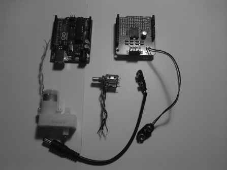
Figure 3-8. The hardware for this project
Configuring the Hardware
![]() Note This book will sometimes refer to “potentiometer” as “pot.”
Note This book will sometimes refer to “potentiometer” as “pot.”
First, you will want to connect the motor shield to the top of the Arduino. Next, we need to connect the potentiometer to the Arduino. The middle wire of the potentiometer will connect to analog pin 0, and the first and last wires will be connected to the +5V pin and ground respectively. After you have the potentiometer connected, connect the motor to port A on the Motor Shield. Finally, connect the USB cable from the computer to the Arduino. See Figures 3-9 and 3-10 to ensure you have everything connected properly. If so, you're ready to move on to creating the software for this project.
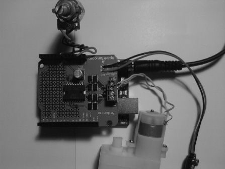
Figure 3-9. The motor is connected to motor port A on the motor shield, and the potentiometer is connected to analog pin 0, the power (+5V) pin, and ground on the Arduino.
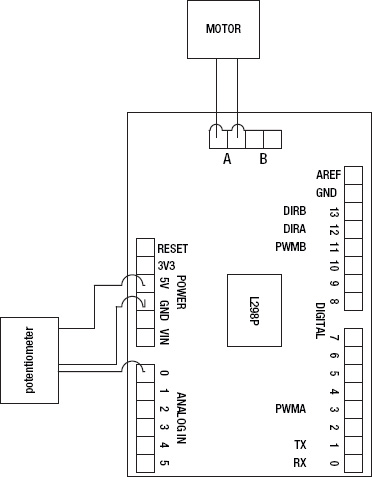
Figure 3-10. The schematic for this project
Writing the Software
We will be using analog pins and digital PWM pins for this project, so we will use analogRead() and analogWrite() functions to allow communication from the pot to the motor. Listing 3-2 provides the code for this project.
Listing 3-2. Contolling the Speed of the Motor
const int potPin = A0;   // A0 refers to analog pin 0

const int motorPin = 3;


int potVal = 0;

int mappedPotVal = 0;


void setup()

{

  pinMode(potPin, INPUT);
pinMode(motorPin, OUTPUT);
}
void loop()
{
potVal = analogRead(potPin);
mappedPotVal = map(potVal, 0, 1023, 0, 255);
analogWrite(motorPin, mapedPotVal);
}
This code starts off with the declarations potPin = A0, motorPin = 3, potVal = 0, and mappedPotVal = 0. Next, we move on to the setup structure, where potPin is set to an input, and motorPin is set to an output. After that, in the loop structure, potVal is set to equal the analog pin potPin. Finally, we scale the potentiometer data using the map() function:
map(potVal,0,1023,0,255);
This function scales the potentiometer value from 0 to 255, which is what the PWM uses as its value to control the speed of the motor.
![]() Note The
Note The map() functions signature looks like this:
map(sensor Value, min sensor scale, max sensor scale, min scale to, max scale to);
After the code finishes scaling the potentiometer values, the scaled values are sent to the PWM pin 3, which was initialized as motorPin.
The next section will add to the first project you created in this chapter. We will be controlling multiple motors with buttons.
Project 3-3: Controlling Multiple Motors with the Arduino
In this section, we will discuss the application of controlling two motors with the Arduino and the motor shield. This will help us understand how the Arduino communicates with multiple motors using switches (or buttons). We will be using multiple motors in the final project of this chapter; the only difference is that we will use buttons to control the motors in this project.
Gathering the Hardware
Figure 3-11 shows the hardware being used for this project, minus the 9V battery, 9V connector, and solderless breadboard:
- Arduino Duemilanove (or UNO)
- Motor shield
- Two 6V motors
- Two buttons or switches
- Solderless bread board
- 9V battery
- 9V battery connector
- Extra wire
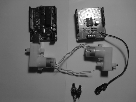
Figure 3-11. The hardware for this project
Configuring the Hardware
As in the first two examples, first connect the motor shield to the Arduino. In this example, there are two push buttons. The first of your buttons should have one wire connected to digital pin 9 and the other to ground. Next, connect one of the wires from the second button or switch to digital pin 10 on the Arduino; the other wire should be connected to ground. The motors are connected to digital pins 3 and 11 to take advantage of the PWM pins (we will not be using the PWM pins in this section; all you need to know is that the motors are connected to ports A and B on the motor shield). Figures 3-12, 3-13, and 3-14 illustrate the hardware setup.
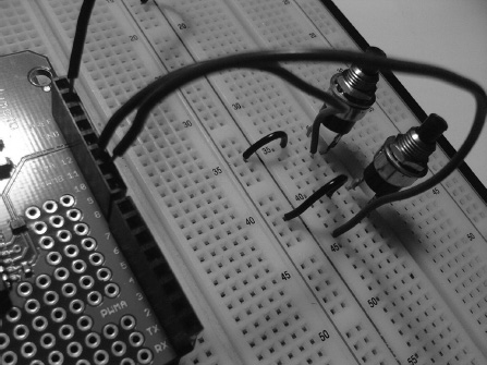
Figure 3-12. The push buttons are connected to digital pins 9 and 10; then, they are connected to ground on the Arduino.
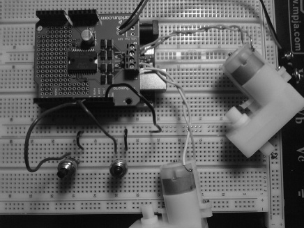
Figure 3-13. The motors are connected to motor ports A and B, and the switches are connected to digital pins 9 and 10 and ground.
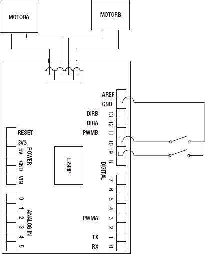
Figure 3-14. The schematic for this project
Writing the Software
This software will need to work with the two buttons we connected in the previous sections; we will use the digitalWrite() and digitalRead() functions to communicate with the Arduino. One button will turn on the motor at port A on the motor shield, and the other button will turn on the motor on port B of that shield. Listing 3-3 provides the code for this project.
Listing 3-3. Controlling Multiple Motors
const int button1Pin = 10; // Sets buttonPin to digital pin 10

const int motor1Pin1 = 3; // Sets motorPin to digital pin 3

const int button2Pin = 9; // Sets buttonPin to digital pin 9

const int motor2Pin = 11; // Sets motorPin to digital pin 11


int buttonVal1 = 0; // Will pass button value here
int buttonVal2 = 0; // Will pass button value here
void setup()
{
pinMode(button1Pin, INPUT); // Makes buttonPin an input
pinMode(motor1Pin, OUTPUT); // Makes motorPin an output
pinMode(button2Pin, INPUT); // Makes buttonPin an input
pinMode(motor2Pin, OUTPUT); // Makes motorPin an output
digitalWrite(button1Pin, HIGH); // Activates the pull-up resistor
// If we did not have this, the switch would not work
// correctly.
digitalWrite(button2Pin, HIGH); // Activates the pull-up resistor
// If we did not have this, the switch would not work
// correctly.
}
void loop()
{
buttonVal1 = digitalRead(button1Pin); // Whatever is at buttonPin is sent to buttonVal1
buttonVal2 = digitalRead(button2Pin); // Whatever is at buttonPin is sent to buttonVal2
if (buttonVal1 == 1)
{
digitalWrite(motor1Pin, HIGH); // Turn motor on if buttonVal equals one
}
else
{
digitalWrite(motor1Pin, LOW); // Turns motor off for all other values
}
if (buttonVal2 == 1)
{
digitalWrite(motor2Pin, HIGH); // Turns motor off for all other values
}
else
{
digitalWrite(motor2Pin, LOW); // Turns motor off for all other values
}
}
This code initializes all of the pins and buttonVal1, buttonVal2 to 0. In the setup structure, we set each pin as an input if it is a button and an output if it is a motor. After we set up the pins, we need to activate the two pull up resistors for the buttons on the Arduino:
digitalWrite(buttonPin1, HIGH);

digitalWrite(buttonPin1, HIGH);
Next, we enter a loop structure where we set buttonVal1 to the value on buttonPin1 and buttonVal2 to the value on buttonPin2. We then create two conditional statements that will send a high value to motorPin1 if buttonVal1 is equal to 1. Finally, in the other if statement, we say that if buttonVal2 is equal to one, the motorPin2 will turn on. That's it; this project should allow us to control multiple motors with the help of the H-bridge.
Now that we have completed this project, we can create another project that will help you understand how to control both speed and direction of a motor.
Project 3-4: Controlling Speed and Direction
Among the reasons an H-bridge is so useful are that it allows us to switch the direction of a motor and to control speed of the motor. This project will show you how to control a motor's speed and direction with a potentiometer and a switch.
Gathering the Hardware
Figure 3-11 shows the hardware being used for this project, minus the 9V battery, 9V connector, and solderless breadboard:
- Arduino Duemilanove (or UNO)
- Motor shield
- 10kohm potentiometer
- Switch (single-pole-single-throw switch)
- 6V motor
- 9V battery
- 9V battery connector
- Extra wire (if needed)
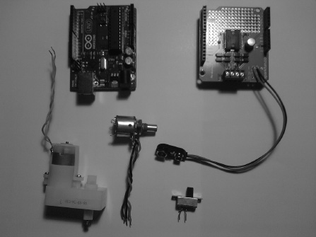
Figure 3-15. The hardware for this project
Configuring the Hardware
The first thing you need to do is connect the motor shield to the Arduino. Second, you will need to connect the potentiometer to analog pin 0, the +5V pin, and ground, like we did in the second project of this chapter. Next, you will need to connect the on/off switch from digital pin 10 to ground as you did in Project 3-1; this switch should be a single-pole-single-throw (SPST) switch. Finally, connect the USB from the computer to the Arduino. Figures 3-16, 3-17, and 3-18 show the configuration for this project.
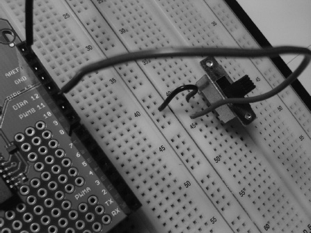
Figure 3-16. The switch is connected to digital pin 10 and ground on the Arduino.
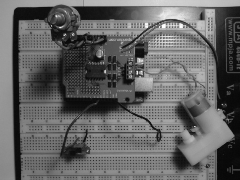
Figure 3-17. The motor is connected to motor port A, and the potentiometer is connected to analog pin 0, the +5V pin, and ground. Also, the switch is connected to digital pin 10 and ground.
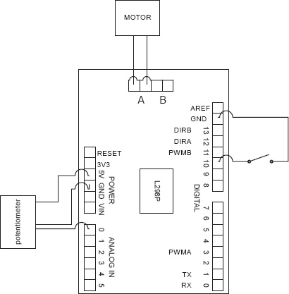
Figure 3-18. The schematic for this project
Writing the Software
In this project, we need to use both analog and digital pins. The analog pin will be used to control the speed of the motor, and the digital pin to control the direction of the motor (via the H-bridge and the hex inverter). The hex inverter inverts the signal of one of the pins, which will switch the polarity of the motor. For example, if the H-bridge is sent a value of 1, the hex inverter reads in a 0 and sends that to the other input pin on the H-bridge causing the motor to turn in a clockwise direction (for more information on this process, please see http://en.wikipedia.org/wiki/H_bridge). Listing 3-4 provides the code for this project.
Listing 3-4. Controlling Speed and Direction
const int switchPin = 10;

const int potPin = A0;

const int motorPin = 3;


int switchVal = 0;

int potVal = 0;

int mapedPotVal = 0;


void setup()
{
pinMode(switchPin, INPUT);
pinMode(potPin, INPUT);
pinMode(motorPin, OUTPUT);
digitalWrite(switchPin, HIGH);
}
void loop()
{
switchVal = digitalRead(switchPin);
potVal = analogRead(potPin);
mapedPotVal = map(potVal, 0, 1023, 0, 255);
analogWrite(motorPin, mapedPotVal);
if (switchVal == 1)
{
digitalWrite(12, HIGH); // direction (clockwise) of motor A port
}
else
{
digitalWrite(12, LOW); // direction (counter-clockwise) of motor A port
}
}
First, this code initializes switchPin, potPin, motorPin, switchVal, potVal, and mappedPotVal. Then, in the setup structure, we set switchPin and potPin to inputs and motorPin to an output. Next, we activate the pull-up resistor with the digitalWrite() function. After that, in the loop structure, we set switchVal equal to the reading on switchPin and set the value of potVal to the reading on potPin. Next, we set mappedPotVal equal to the scaled values 0 to 255 using the map() function; mappedPotPin is then sent to motorPin. Finally, we control the motor with a conditional if statement. If switchVal is equal to 1, the motor will turn clockwise; otherwise, the motor will turn counterclockwise.
Project 3-5: Controlling Motors with Serial Commands
Now that you understand the basics of motor control, we can visit our example company to see if it has any projects for us to complete that require using the Arduino to control motors. It does! So our first steps are gathering the requirements and creating the requirements document.
Requirements Gathering
The customer has set up a meeting and has several requirements for a robot controlled by the Arduino using serial communication; the Arduino will drive two motors with the help of a motor shield. The client's project also requires that the user send motor's parameters in a comma-separated format to the serial monitor (shown in Figure 3-19) as follows:
1,255,1,255
In this format, the first parameter is the direction of motor A; the second parameter is the speed of motor A; the third is the direction of motor B, and the forth is the speed of motor B. The serial monitor displays the information in this format:
Motor A

1

255

Motor B

1

255
![]() Note Comma-separated format is a very common way for data to be passed and collected from the Arduino and many other peripherals.
Note Comma-separated format is a very common way for data to be passed and collected from the Arduino and many other peripherals.
The company wants each of the comma-separated parameters to go to these specific pins. The pins are: 12, 3, 13, and 11. Another requirement is that the final prototype needs to be configured on a chassis once the hardware and software have been tested.
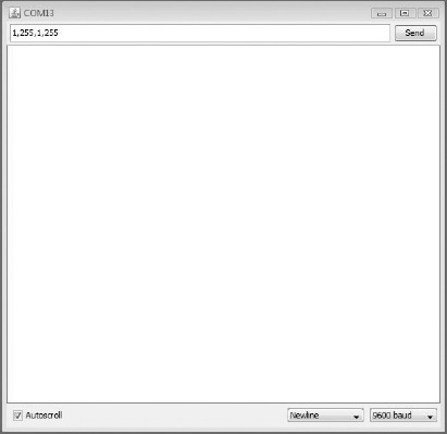
Figure 3-19.The user will type values for the direction and speed of the motors into the serial monitor shown here.
![]() Note When using the serial monitor, make sure that newline is selected in the Line Ending parameter.
Note When using the serial monitor, make sure that newline is selected in the Line Ending parameter.
Now that you have notes for Project 3-5, we can configure them into a requirements document.
Gathering the Hardware
Figure 3-20 shows the following hardware, which you'll need for this project:
- Arduino Duemilanove (or UNO)
- Motor shield
- Two 6V motors
- Solderless breadboard
- Robot chassis (for use only after the hardware and software has been tested)
- USB cable
- 9V battery
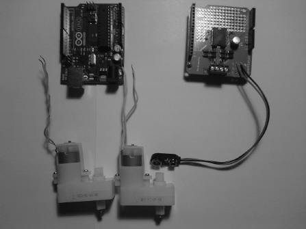
Figure 3-20. Hardware for this project
Outlining the Software Requirements
Following are the software requirements:
- Create a program that sends comma-separated data to the Arduino to control the speed and direction of two motors. The user should enter the data in this format:
1,255,1,255 - The first and third perameters in the comma-separated values are the direction of motors A and B, and the second and forth parameters are the speeds of motors A and B.
- The serial monitor should output the data in this format:
Motor A

1

255

Motor B

1

255 - The overall purpose of this program is to control the speed and direction of two 6V motors.
Now that we have the hardware and software requirements, we can create the software's flowchart. Figure 3-21 shows the flowchart for this project.
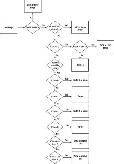
Figure 3-21. Flowchart for this project
Configuring the Hardware
The configuration of this project is to first connect the Arduino to the motor shield; next, connect the two motors to ports A and B on the motor shield. Finally, connect the USB to the Arduino and computer. Figures 3-22 and 3-23 illustrate the hardware configuration.
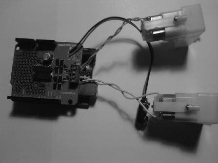
Figure 3-22. The motors are connected to motor ports A and B on the motor shield.
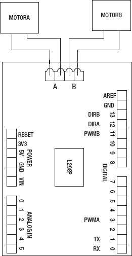
Figure 3-23. The schematic for this project.
Writing the Software
Now, we will move on to the software for this project. We need to communicate with both digital and analog pins. Unlike in our previous projects, here we will be interfaceing data by means of serial communication, so we have to send in multiple sets of data, specifically the direction of motor A, speed of motor A, direction of motor B, and speed of motor B. We need to use comma-seperated fomat to parse the data to their respective digital or analog pins. After that, we need to display the data on the serial monitor in this fomat:
Motor A

1

255

Motor B

1

255
Listing 3-5 shows the code.
Listiing 3-5. Code for the Client's Project
const int fields = 4; // amount of values excluding the commas

int motorPins[] = {12,13,3,11}; // Motor Pins

int index = 0; // the current field being received

int values[fields]; // array holding values for all the fields


void setup()

{

  Serial.begin(9600); // Initialize serial port to send and receive at 9600 baud


  for (int i; i <= 3; i++)        // set LED pinMode to output

  {

    pinMode(motorPins[i], OUTPUT);

  }


  Serial.println("The Format is: MotoADir,MotoASpe,MotorBDir,MotoBSpe
");  //
 is a new

                                              // line constant that will output a new line

}


void loop()

{


if( Serial.available())

  {

    char ch = Serial.read();

  if(ch >= '0' && ch <= '9') // If it is a number 0 to 9

    {

      // add to the value array and convert the character to an integer

      values[index] = (values[index] * 10) + (ch - '0'),

    }

  else if (ch == ',') // if it is a comma increment index

    {

      if(index < fields -1)

      index++; // increment index

    }

  else

    {


      for(int i=0; i <= index; i++)

        {

           if (i == 0)

           {

             Serial.println("Motor A");

             Serial.println(values[i]);

           }

           else if (i == 1)

           {

             Serial.println(values[i]);
}
if (i == 2)
{
Serial.println("Motor B");
Serial.println(values[i]);
}
else if (i == 3)
{
Serial.println(values[i]);
}
if (i == 0 || i == 1) // If the index is equal to 0 or 2
{
digitalWrite(motorPins[i], values[i]); // Here we see a logical error
}
if (i == 2 || i == 3) // If the index is equal to 1 or 3
{
analogWrite(motorPins[i], values[i]); // Here we see a logical error
}
values[i] = 0; // set values equal to 0
}
index = 0;
}
}
}
Notice that the code will run—with unexpected results. Look at the initialization of motorPins and you'll see that the array is out of order with the format we were given: motor A direction, motor A speed, motor B direction, motor B speed. This is one of those pesky logical errors, and it brings us to the next section, debugging the Arduino software.
Debugging the Arduino Software
Now that we have discoved the logical error, we need to fix it. Listing 3-6 contains the corrected array in bold.
Listing 3-6.Corrected Code for Project 3-5
const int fields = 4; // amount of values excluding the commas.

int motorPins[] = {12,3,13,11}; // Motor Pins

int index = 0; // the current field being received

int values[fields]; // array holding values for all the fields


void setup()

{

  Serial.begin(9600); // Initialize serial port to send and receive at 9600 baud


  for (int i; i <= 3; i++)        // set LED pinMode to output

  {

    pinMode(motorPins[i], OUTPUT);
}
Serial.println("The Format is: MotoADir,MotoASpe,MotorBDir,MotoBSpe
");
}
void loop()
{
if( Serial.available())
{
char ch = Serial.read();
if(ch >= '0' && ch <= '9') // If the value is a number 0 to 9
{
// add to the value array
values[index] = (values[index] * 10) + (ch - '0'),
}
else if (ch == ',') // if it is a comma
{
if(index < fields -1) // If index is less than 4 - 1
index++; // increment index
}
else
{
for(int i=0; i <= index; i++)
{
if (i == 0)
{
Serial.println("Motor A");
Serial.println(values[i]);
}
else if (i == 1)
{
Serial.println(values[i]);
}
if (i == 2)
{
Serial.println("Motor B");
Serial.println(values[i]);
}
else if (i == 3)
{
Serial.println(values[i]);
}
if (i == 0 || i == 2) // If the index is equal to 0 or 2
{
digitalWrite(motorPins[i], values[i]); // Write to the digital pin 1 or 0
// depending what is sent to the Arduino.
}
if (i == 1 || i == 3) // If the index is equal to 1 or 3 {
analogWrite(motorPins[i], values[i]); // Write to the PWM pins a number between
// 0 and 255 or what the person entered
// in the serial monitor.
}
values[i] = 0; // set values equal to 0
}
index = 0;
}
}
}
At this point, I want to discuss the finer details of this code, as we have gone over similar code before. The first thing I want to point out is where we parse the data to be sent to the correct pins:
  if(ch >= '0' && ch <= '9') // If the value is a number 0 to 9

    {

      // add to the value array

      values[index] = (values[index] * 10) + (ch - '0'),

    }

  else if (ch == ',') // if it is a comma

    {

      if(index < fields -1) // If index is less than 4 - 1

      index++; // increment index

    }

  else

           // This is where the data is passed to the digital and analog pins
This part of the code first checks to see if an input character from 0 to 9 exists. If so, it converts the character type to a integer type by subtracting by 0, which has an integer value of 48, and tells the microcontroller to see this value as an integer instead of a character. Next, it checks to see if the character is a comma. If so, it will check to see if the index is greater than or equal to 3. If the value is less than 3, it will increment the index value. The if-elseif statement handles any other values such as numerical values, which is what the characters are converted to.
Next, I would like to discuss the parsing of the data to the digital and analog pins and how we formatted the data on the serial monitor. The code looks like this:
for(int i=0; i <= index; i++)

        {

           if (i == 0)

           {

             Serial.println("Motor A");

             Serial.println(values[i]);

           }

           else if (i == 1)

           {

             Serial.println(values[i]);

           }

           if (i == 2)

           {

             Serial.println("Motor B");

             Serial.println(values[i]);
}
else if (i == 3)
{
Serial.println(values[i]);
}
if (i == 0 || i == 2) // If the index is equal to 0 or 2
{
digitalWrite(motorPins[i], values[i]); // Write to the digital pin 1 or 0
// depending what is sent to the Arduino.
}
if (i == 1 || i == 3) // If the index is equale to 1 or 3
{
analogWrite(motorPins[i], values[i]); // Write to the PWM pins a number between
// 0 and 255 or what the person entered
// in the serial monitor.
}
The for loop iterates through all of the indexes (in this case, 0–3). The first and second if statements and if-elseif statements are printing the data to the serial monitor, which is where we get the format:
Motor A

1

255

Motor B

1

255
Do you see an eaiser way of programming this format? (Hint: use switch.) After those if statements, we come to the code that seperates the data to its appropriate pin, which is what the company asked for, so the format this code accepts is motor A direction (0 or 1), motor A speed (0 to 255), motor B direction (0 or 1), and motor B speed (0 to 255). Now that we have the software sorted out, we can focus on testing the hardware.
Troubleshooting the Hardware
The beautiful thing about using a prototype shield is that it normally has no problems, but in the small chance you do have issues, such as if your motors turn the incorrect way or move at incorrect speeds, here's what you should check. For the first case, make sure your motors are connected correctly. If they are not, switch the terminals of the motors and see if they move in the correct direction. If the motors are still moving in the wrong direction, make sure your code is correct.
![]() Note If you need to, copy and paste the code from the “Debugging the Arduino Software section” to the Arduino IDE, to make sure everything is correct.
Note If you need to, copy and paste the code from the “Debugging the Arduino Software section” to the Arduino IDE, to make sure everything is correct.
Finished Prototype
The company's requirements document says we need to have a chassis for this project to be complete. Since we have tested both the hardware and software, we can now mount the hardware on a chassis so the robot can move. Figures 3-24 and 3-25 illustrate the finished prototype.
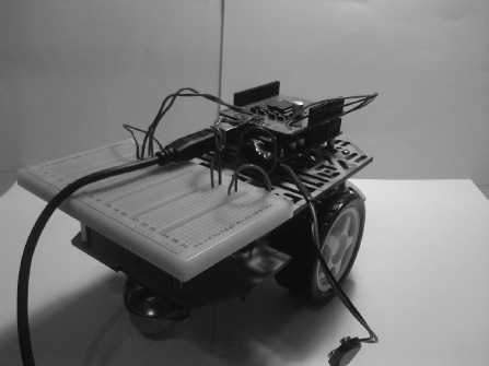
Figure 3-24. The finished prototype
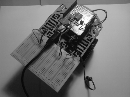
Figure 3-25. Top view of the finished prototype
![]() Note Try to keep pressure off of the motors' connectors while you build the chassis and attach the wires to the Arduino; if you put to much pressure on the connectors, you may break them.
Note Try to keep pressure off of the motors' connectors while you build the chassis and attach the wires to the Arduino; if you put to much pressure on the connectors, you may break them.
Summary
In this chapter, we discussed motor control and how it can be used to give a robot life. To do this, you first had to understand what an H-bridge is and how it can be used to drive motors. Next, we went over the basics of motor control by building several projects. After that, we focused on using the engineering process to complete a project to a client's specifications. In this project, we controlled multiple motors using a serial monitor to update the motor settings (i.e., motor speed and direction). You also learned about the comma-seperated data format and how it is used to parse data. Now that this project is done, you can go out in the world and use motors on whatever project you deem worthy.