
C H A P T E R 11
Controlling Your Project: Bluetooth Arduino
In this chapter, we will build a robot that we can control wirelessly, using a Bluetooth shield that we’ll also create in this chapter. We will continue to use the LabVIEW software that we created in the previous chapter, with a few minor tweaks. However, the Arduino software will change substantially, as we will not be using the GPS shield or microSD shield. We will not be doing any preliminary projects for this chapter, as we have worked with the Bluetooth Mate Silver from SparkFun before. Instead, we get right to the customer’s requested project. Of course, after all that’s done, we will troubleshoot any issues that the hardware configuration might have encountered. Then, we will debug any issues that occurred with that the LabVIEW and Arduino software. We should then have a finished prototype, ready for the customer to use.
Gathering Requirements and Creating the Requirements Document
The customer would like a robot that they can control wirelessly with an Xbox controller, using the LabVIEW software, created in the previous chapter, and the Arduino. The only new requirements are that the robot needs to use the Bluetooth Mate Silver, and the Bluetooth Mate Silver needs to be mounted on an Arduino shield for easy connection and disconnection. Again, we will not use the microSD shield or the GPS shield for this project, as the customer wants a wireless robot (using Bluetooth) that they can control using the Xbox controller.
The LabVIEW software will need to use a baud rate of 115200 because the Bluetooth Mate Silver is configured at this rate. The LabVIEW software will also use a different SubVI that no longer has the functionality to send “G” to the serial port. The customer wants a control added to the LabVIEW software to control the baud rate. The customer also wants any code associated with the GPS and microSD shield removed to free up memory resources on the Arduino. The robot should still use the same chassis from the previous project. The customer needs the robot to be powered by two 9V batteries. The robot needs to operate for 15 to 30 minutes (this will depend on the terrain).
Now that we have the notes for this project, we can compile them into a requirements document that will help us stay focused on the tasks for this project. The first section will discuss the hardware requirements for this project. Figure 11-1 shows the hardware used in this project, excluding the 9V batteries and the 9V battery connectors.
Gathering Hardware
Figure 11-1 shows some of the hardware being used in this project. (Not pictured: chassis from Chapter 4, two 9V batteries, two 9V battery connectors.)
- Arduino Deumilanove (or UNO)
- Bluetooth Mate Silver
- Chassis and motor driver from previous project
- DIY shield for Arduino from Adafruit
- 6-pin female stackable header
- Two 9V batteries
- Two 9V connectors (see the final project in Chapter 7 final project for more details)
- Extra wire
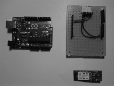
Figure 11-1. Hardware for this project
![]() Note The DIY shield (Bluetooth shield) will be created in the “Configuration the Hardware” section of this chapter.
Note The DIY shield (Bluetooth shield) will be created in the “Configuration the Hardware” section of this chapter.
Gathering Software
The following list explains the software requirements for this project:
- Modify the LabVIEW software to use 115200 baud rate instead of 9600. The customer wants this to be a control rather than a constant.
- The SubVI will no longer have the functionality to send a “G” character. A new SubVI will take its place with the modifications.
- Modify the Arduino software so that it no longer uses any code associated with the GPS shield or the microSD shield.
Now that we have the hardware and software requirements, we can create the flowchart, shown in Figure 11-2, which will help guide us through the software portion of this project.
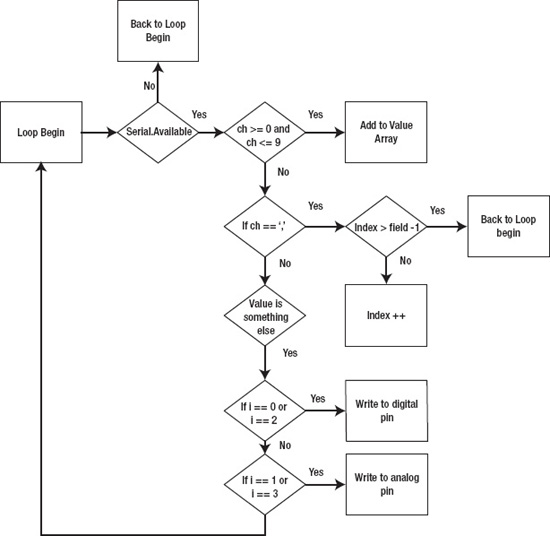
Figure 11-2. Flowchart for this project
Next, let’s move on to configuring the hardware for this project.
Configuring the Hardware
The first thing we will do is create the Bluetooth shield using the DIY shield from Adafruit. This kit includes one special 8-pin female stackable header; it is special because all of its pins are slanted so that you can use it with the Arduino (you could also use the Proto shield from SparkFun for this project).
Begin by putting all of the stackable headers onto the DIY shield so that you can determine where the headers should be. To do this, put the special 8-pin female stackable header onto the DIY shield and attach it to the Arduino. Now you should be able to put the rest of the headers on. Then, use a marker to mark where your headers are located. Figure 11-3 shows this process.

Figure 11-3. You’ve added the headers, marked them, and are now ready to solder.
![]() Note Make sure that the special 8-pin female stackable header has its pins facing toward the other 8-pin stackable header; otherwise, the shield will not connect correctly to the Arduino. Figure 11-4 shows the directions the pins should face on the special 8-pin stackable header.
Note Make sure that the special 8-pin female stackable header has its pins facing toward the other 8-pin stackable header; otherwise, the shield will not connect correctly to the Arduino. Figure 11-4 shows the directions the pins should face on the special 8-pin stackable header.
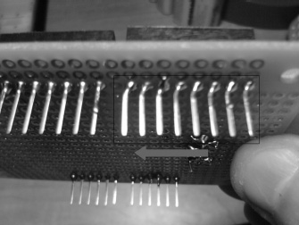
Figure 11-4. Make sure that the special 8-pin female stackable header is pointing toward the other 8-pin header.
Soldering the Headers
Now that you’ve finalized the location for the headers, you can solder them to the DIY shield. Figure 11-5 shows this process.
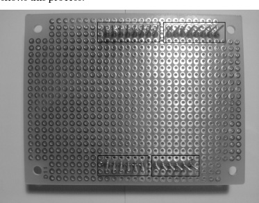
Figure 11-5. Solder on the headers that will connect to the Arduino.
Next, you need to solder on the 6-pin stackable header that will allow you to connect the Bluetooth Mate Silver to the Bluetooth shield. After you have the 6-pin header soldered on, you will need to cut the extra pin length off; otherwise, the header will touch the Arduino, and that can have severe consequences. Figures 11-6 and 11-7 show this process.
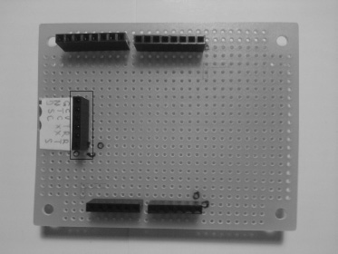
Figure 11-6. Solder on the 6-pin header that will allow the Bluetooth Mate Silver to attach to the Bluetooth shield.
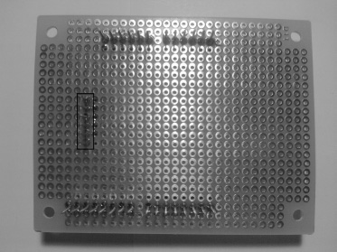
Figure 11-7. Solder the 6-pin header.
Now that we have connected all of the headers, let’s move ahead and work on the pins and more.
Pins and Beyond
It might be a good idea to make sure you can attach the Bluetooth shield to the Arduino, so gently place the Bluetooth shield onto the Arduino. If it fits, that’s great. If it doesn’t, you might need to make sure that the pins are not slanting. After you have made sure that the Bluetooth shield can attach to the Arduino, take it off the Arduino. Then, solder on the ground pin of the Bluetooth Mate Silver header to the ground pin on the Bluetooth shield, and solder the CTS and RTS pins to one another. Figures 11-8 through 11-10 show this process.

Figure 11-8. Solder the ground wire from the 6-pin header to the ground on the Bluetooth shield.

Figure 11-9. Solder the CTS and RTS pins together from the 6-pin header.
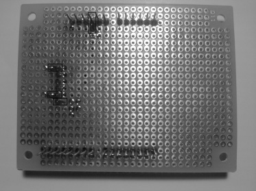
Figure 11-10. Solder the ground from the 6-pin header to the ground on the Bluetooth shield, and then solder the CTS and RTS together from the 6-pin header.
Next, you need to solder the VCC pin of the Bluetooth Mate Silver header to the power (+5V) on the Bluetooth shield. Figures 11-11 and 11-12 show this process.
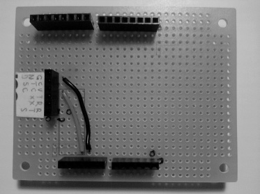
Figure 11-11. Solder the VCC pin on the 6-pin header to the +5V pin on the Bluetooth shield.
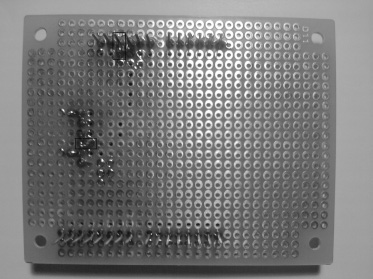
Figure 11-12. Solder the VCC wire.
Now you need to solder the TX pin on the Bluetooth Mate Silver header to the RX pin on the Bluetooth shield. Then, solder the RX pin on the Bluetooth Mate Silver header to the TX pin on the Bluetooth shield. Figures 11-13 and 11-14 show this process.
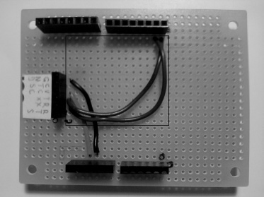
Figure 11-13. Solder the RX pin from the 6-pin header to the TX pin on the Bluetooth shield. Then, solder the TX pin from the 6-pin header to the RX pin on the Bluetooth shield.
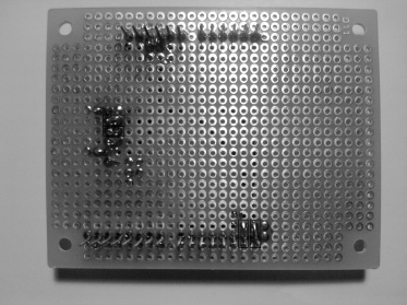
Figure 11-14. Solder the RX and TX wires.
Next, you need to add the Bluetooth Mate Silver to the 6-pin header. That should do it; you’ve now finished the Bluetooth shield. We will not connect the Bluetooth shield to the Arduino until we upload the software. Figure 11-15 shows the Bluetooth Mate Silver attached to the Bluetooth shield.
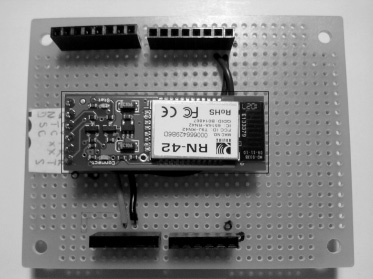
Figure 11-15. Attach the Bluetooth Mate Silver to the Bluetooth shield.
Configuring the Chassis and Arduino
Now that we have finished creating the Bluetooth shield, we can complete the configuration of the chassis and Arduino. To complete the partial hardware configuration, attach the Arduino to the chassis. We only need to do a partial hardware configuration because we cannot add the Bluetooth shield that we created in the previous section, as it will conflict with the serial port that uploads the code to the Arduino. Figure 11-16 shows the partial hardware configuration.
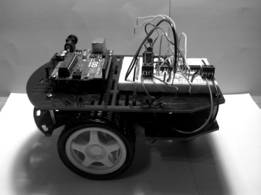
Figure 11-16. Partial hardware configuration for this project
Now that we have completed the Bluetooth shield, and partially configured the hardware, we can create the software that will run on the Arduino and the software that will allow us to integrate the Bluetooth Mate Silver and the Xbox controller. In the next section, we will discuss writing the software.
Writing the Software
We will first work on the LabVIEW software for this project. Open ChapterTenFinalProject.vi, and the Front Panel should open.
Reviewing the LabVIEW Software
Open the Block Diagram by going to Window ![]() Show Block Diagram. The first modification that you need to complete is to replace
Show Block Diagram. The first modification that you need to complete is to replace ScaleandControl.vi with ScaleandControlChapter11.vi; this SubVI no longer uses “button A” to send the “G” command to the serial port. To do this, first left-click ScaleandControl.vi in the Block Diagram, then press the Delete key. The LabVIEW software should have a broken arrow and some broken wires. Figure 11-17 shows the Block Diagram with no ScaleandControl.vi.

Figure 11-17. Delete the ScaleandControl.vi from the Block Diagram.
Now you need to get rid of the broken wires in the Block Diagram. To do this, press Ctrl+B. Figure 11-18 shows this process.
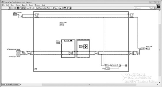
Figure 11-18. Press Ctrl+B to delete the broken wires.
Now we need to add ScaleandControlChapter11.vi to the Block Diagram and connect it to the appropriate controls and indicators. First, connect axis info terminal from the Acquire Input Data function to the axis info terminal on ScaleandControlChapter11.vi. Next, connect the String terminal on ScaleandControlChapter11.vi to the Write Buffer terminal on the VISA Write function. Figure 11-19 shows this process.
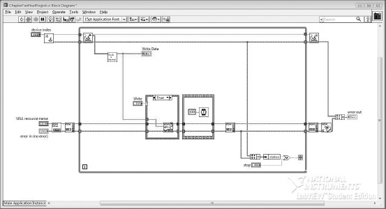
Figure 11-19. Connect the terminals of ScaleandControlChapter11.vi to the appropriate areas.
Finally, we need to add the baud rate control to the Front Panel. To do this, go to the Block Diagram and right-click the VISA Configure Serial Port’s baud rate terminal; a pop-up menu should appear. Go to Create ![]() Control to add a control to the Block Diagram and Front Panel. Go to the Front Panel and move the baud rate control to an appropriate position. Figures 11-20 and 11-21 show the completed LabVIEW software for this project.
Control to add a control to the Block Diagram and Front Panel. Go to the Front Panel and move the baud rate control to an appropriate position. Figures 11-20 and 11-21 show the completed LabVIEW software for this project.
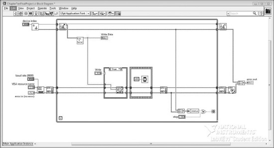
Figure 11-20. Add the baud rate control to the Block Diagram and the Front Panel.
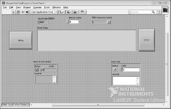
Figure 11-21. Completed LabVIEW application
Reviewing the Arduino Software
Now that we have completed the LabVIEW software, we need to take a look at the Arduino software for this project. Listing 11-1 shows the code that we will upload to the Arduino.
Listing 11-1. Code for This Project
const int fields = 4; // how many fields are there? right now 4

int motorPins[] = {4,5,7,6}; // Motor Pins

int index = 0; // the current field being received

int values[fields]; // array holding values for all the fields


void setup()

{

  Serial.begin(115200); // Initialize serial port to send and receive at 115200 baud


  for (int i; i <= 3; i++)        // set motors pinMode to output

  {

    pinMode(motorPins[i], OUTPUT);

    digitalWrite(motorPins[i], LOW);

  }

}
void loop()

{


  if( Serial.available())

  {

    char ch = Serial.read();


    if(ch >= '0' && ch <= '9') // If the value is a number 0 to 9

    {

      // add to the value array

      values[index] = (values[index] * 10) + (ch - '0'),

    }

    else if (ch == ',') // if it is a comma

    {

      if(index < fields -1) // If index is less than 4 - 1...

        index++; // increment index

    }

    else

    {


      for(int i=0; i <= index; i++)

      {

        if (i == 0 || i == 2)  // If the index is equal to 0 or 2

        {

          digitalWrite(motorPins[i], values[i]); // Write to the digital pin 1 or 0

          // depending what is sent to the arduino.

        }


        if (i == 1 || i == 3) // If the index is equale to 1 or 3

        {

          analogWrite(motorPins[i], values[i]);  // Write to the PWM pins a number between

          // 0 and 255 or what the person has enter

          // in the serial monitor.

        }


        values[i] = 0; // set values equal to 0


      }


      index = 0;

      Serial.flush();

    }


  }


}
Now, let’s examine the code in more detail.
First, we get rid of everything to do with the GPS shield and the microSD shield. Then, we add on a new piece of code right after the index = 0; (the one at the end of the code) statement. The Serial.Flush() function flushes the buffer on the serial port, allowing for more data to be processed. That’s it for the Arduino software.
Uploading the Software and Attaching the Bluetooth Shield
Now we need to upload this program to the Arduino. After you have uploaded the code, you can attach the Bluetooth shield to the Arduino (which should be attached to the chassis). Then, connect the power (+5V) and ground from the motor driver to the power (+5V) and ground on the Bluetooth shield. Next, connect pin 7 from the H-bridge to digital pin 4 on the Bluetooth shield. Then, connect pin 1 on the H-bridge to digital pin 5 on the Bluetooth shield. After that, connect pin 9 on the H-bridge to digital pin 6 on the Bluetooth shield. Finally, connect pin 10 on the H-bridge to digital pin 7 on the Bluetooth shield. The motor driver was created in Chapter 4. Figure 11-22 shows the completed hardware configuration for this project.
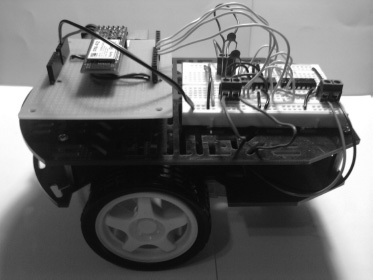
Figure 11-22. Completed hardware configuration for this chapter
![]() Note Make sure you use new 9V batteries.
Note Make sure you use new 9V batteries.
Operating the Robot
Now you should be ready to operate the Bluetooth robot. There is a particular sequence that you should follow; otherwise, you could run into issues with the robot. Here is the sequence:
- Plug in the Xbox controller to one of your USB ports.
- Attach one 9V battery to the motor driver and one 9V battery to the Arduino.
- Open
ChapterTenFinalProject.vithat we modified in this chapter, and the Front Panel should appear.- Make sure that the baud rate control is set to 115200, the correct COM port is selected, and the correct device index is selected for the Xbox controller (mine is set to 4).
- Start the LabVIEW application by clicking the white arrow.
- Wait until the Bluetooth Mate Silver’s LED is solid (not blinking) before you press the Write button on the Front Panel.
- You should now be able to control the Bluetooth robot with the Xbox controller.
There are also shutdown procedures that you should use. They are as follows:
- Press the Write button on the Front Panel (you should no longer be able to control the Bluetooth robot).
- Press the Stop button on the Front Panel, and the program should stop.
- Remove the batteries from the Bluetooth robot.
- Disconnect the Xbox controller from the computer.
Now that we have completed the hardware configuration, and we have completed writing the software, we can move on to debugging the software for this project.
Debugging the Software
As long as you followed the configuration of the LabVIEW software correctly, you shouldn’t have any issues with it. If you do have problems, it is more than likely that one of the configuration controls (baud rate, COM port, and device index) is set to the wrong setting (you might have to mess around with the device index in order to get it working correctly). The Arduino software should also be working, but if it is not, make sure that you have removed all of the code associated with the GPS shield and microSD shield. You should now have working software.
Now that we have debugged the software, we can move on to troubleshooting the hardware for this project.
![]() Note It might also be a good idea to make sure you are following the correct startup procedures as explained in the “Writing the Software” section of this chapter.
Note It might also be a good idea to make sure you are following the correct startup procedures as explained in the “Writing the Software” section of this chapter.
Troubleshooting the Hardware
Because we made our own shield, we might have had a few issues with the Bluetooth shield. The first thing you should do is check for continuity of your circuit. For example, if you are having continuity issues with your RX pin (that is, you do not think it is soldered properly and is not connecting from the RX pin on the Bluetooth Mate Silver header to the TX pin on the Arduino), you should put a wire in the RX pin of the Bluetooth Mate Silver header and put another wire in the TX pin of the Arduino. Then, you can use a multimeter to tell whether the two connections have continuity. Figure 11-23 shows this process.
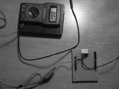
Figure 11-23. Checking whether two terminals are connected; if the multimeter displays “OL,” then the terminals are not connected, which could be an issue.
If you are still having problems, it might be a good idea to make sure that some of your pins are not connecting to the wrong pins; you can do this with the same continuity test, but instead of seeing some resistance (ohm), you should see “OL” (Open Loop, or Over Limit). (For more information on your multimeter, please consult your multimeter user manual.) This means that your terminals are not connected, which is a good thing if you are making sure pins are not touching. Figure 11-24 shows this process.

Figure 11-24. These two terminals are supposed to be disconnected, which is why the multimeter reads “OL”; if it were to read a number, then those two terminals are connecting, which can be an issue.
If everything is working, and you can drive your robot wirelessly, then you are ready to move on to the finished prototype.
Finished Prototype
Now that we have completed the debugging of this project, we can give the customer the finished prototype. Figure 11-25 shows the finished prototype.

Figure 11-25. Finished prototype
Summary
You should now be familiar with the engineering process, as it relates to the Arduino. You can use this process in any project and can also modify it to make it even more robust. Throughout this chapter and this book, we have been using various pieces of hardware to create many different gadgets and robots. For this chapter, we made a robot that we could control wirelessly from a computer with the Xbox controller.
I hope that this book illustrated the engineering process well enough for you to understand how you can implement it in all of your projects. If you want to expand on this project, here are a few things you could do:
- Add GPS location to the robot.
- Add a battery-checking device.
- Make the operating area a bit larger with a ZigBee (there is a kit that you can purchase from SparkFun).
- Make this robot both controlled by the user and autonomous (see the final project in Chapter 7 for information on autonomous vehicles).
I hope you enjoyed reading this book as much as I did writing it, and that the knowledge you gained from the projects we developed will help you in your own future plans.