
C H A P T E R 5
Robot Integration Engineering a GPS Module with the Arduino
In this chapter, we will be discussing GPS and adding it to the customer's robot we built in the previous chapter. You can use GPS for many things, such as tracking a robot or selecting where you want your robot to be. The customer wants to do just that by sending the GPS location of the robot to a microSD card and logging it to a text file. They want to send a separate command to the robot in order to get the latitude and longitude data from GPS.
Throughout this chapter, we will be using a protocol called NMEA. This protocol is used to communicate important GPS-related information. We will also discuss two new libraries. They are TinyGPS (thanks to Mikal Hart: http://arduiniana.org/libraries/tinygps/) and SdFat Library (thanks to Bill Greiman: http://code.google.com/p/sdfatlib/downloads/list). These libraries will help us both communicate with the GPS and create files to store our GPS data. I will also introduce two new shields; they are the microSD shield from Sparkfun. This shield will be used in conjunction with the SdFat library and the GPS shield from Sparkfun. This shield allows you to use a GPS module with your Arduino to get GPS location (but more on these shields later).
After we have discussed the new libraries and shields, we will walk through a few preliminary projects in preparation for the customer's new set of requests. These preliminary projects include writing raw GPS data to the serial monitor, creating a car finder, writing GPS data to a monochrome LCD, logging GPS data, and finally adding to the robot we created in the previous chapter.
Let's start off by reviewing microSD shield and then the NMEA protocol so that you understand what the GPS is displaying.
Hardware Explained: microSD Shield
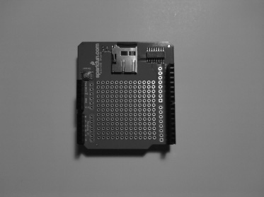
In the GPS data logger project we will create in this chapter, we will use the microSD shield; this shield is used to store data. Because GPS data can be large and the Arduino does not have that much onboard memory, we need to outsource the GPS data to another memory source. This is where the microSD shield comes into play. This particular microSD shield will allow us to use up to a 1GB microSD card (1GB is not fully supported, but it should work). For this chapter, we will be using a 512MB microSD card. Figure 5-1 illustrates the new hardware for this chapter.
![]() Note Make sure you format your microSD card to FAT32.
Note Make sure you format your microSD card to FAT32.
![]() Note The microSD shield uses the same pins as the color LCD shield, so we will not be using the color LCD shield in the final project.
Note The microSD shield uses the same pins as the color LCD shield, so we will not be using the color LCD shield in the final project.
Understanding NMEA Protocol
NMEA stands for “National Marine Electronics Association.” In this section, we discuss three specific NMEA sentences: GPGGA, GPGSV, and GPRMC. We need to understand these NMEA sentences for the first project of this chapter to make sense. Each of these sentences offers different data. The next few sections will discuss the uses and formats of GPGGA, GPGSV, and GPRMC.
- GPGGA: This sentence holds the data for longitude and latitude and other important information about the GPS's fix. Here is the format of the GPGGA command:
$GPGGA, TimeofFix, Lat, dir, Long, dir, FixQual, NumofSats, Altit, unit, HghtofGeoid, unit, emp, emp, CS
The information looks something like this:
GPGGA, 105026, 23456.061, N, 43214,056, W, 1, 04, 0.9, 100.56, M, 56.5, M,,*47
- GPGSV: This sentence holds the satellite information such as signal-to-noise ratios and a few other parameters. Here is the format of the GPGSV command:
$GPGSV, NumofSent, SentNum, NumofSat, PRNnum, Elevation, Azimuth, SNR, CS
The information looks like this:
$GPGSV, 2, 1, 08, 01, 50, 083, 55, (The last 5 pieces of data can happen up to 4 times each sentence), CS
- GPRMC: This sentence holds data that will tell us speed, longitude, and latitude. Here is the format of the GPRMC command:
$GPRMC, TimeofFix, Status, Lat, dir, Long, dir, SpeedOverGround, TrackAngle, date, MagVar, CS
The information looks like this:
$GPRMC, 105019, V, 1234.345, N, 3456.067, W, 025.3, 100.4, 231286, 003.2, W, *6A
Now that you understand NMEA a bit better, we can discuss the TinyGPS library and how it is used in GPS applications.
Libraries Explained: TinyGPS and SdFat Libraries
In this section, you will learn about the TinyGPS library and the SdFat library that we will use throughout this chapter. The first section will cover the TinyGPS library; this library parses the raw GPS data that you will see in the first project. It is important to understand NMEA sentences so that in the first project you can identify whether you are receiving valid data. The next section will discuss the TinyGPS library.
TinyGPS
The first library that will be explained is the TinyGPS library (by Mikal Hart). You can download this library from http://arduiniana.org/libraries/tinygps/. This library is used to parse through the GPS data and make it more understandable. The first thing we need to do in order to use the TinyGPS library is to include the header file:
#include "TinyGPS.h"
After that, we need to create an instance of the TinyGPS:
TinyGPS gps;
Next, we need to create a soft serial (aka software serial) to communicate with the GPS; this was discussed in Chapter 2. After that, we need to use the encode() function to get the GPS data. Here is a code snippet using the encode() function:
#include <NewSoftSerial.h>

#include <TinyGPS.h>


TinyGPS gps;

NewSoftSerial gpsSerial(2,3); // rx and tx

void setup()

{

   // setup code

}

void loop()

{

    while(gpsSerial.available() > 0)

    {

        int data = gpsSerial.read();

        if(gps.encode(data));
        {

            // Processed data

         }

     }

 }
Now that you understand how to set up the TinyGPS library, here are a few functions that give us parsed NMEA data:
TinyGPS get_position(): This function gives us the longitude and latitude direction; it also has the parameter that allows us to check how recent the data is. Here is the format of theget_position()function:
gps.get_position(&lat, &long, &fix_age);
TinyGPS get_datetime: This function returns the values for the date and time; it also has the parameter that allows us to check how recent the data is. Here is the format of theget_datetime()function:
gps.get_datetime(&date, &time, &fix_time);
TinyGPS speed(): This function displays the current speed of the GPS module. Here is the format of the speed function:
unsigned long speed = gps.speed();
Now that you are familiar with the TinyGPS library, we can focus our attention on the SdFat library. The next section will discuss several functions that will allow us to read and write data to a microSD card.
SdFat Library
The SdFat library (by Bill Greiman) allows us to open, create, and send data to a file. You can find this library at http://code.google.com/p/sdfatlib/downloads/list. As usual, we need to add the include files in order to use the SdFat library. They are as follows:
#include <SdFat.h>

#include <SdFatUtil.h>

#include <ctype.h>
After that, we need to declare a few variables that the SdFat libraries use in order to communicate with a file.
Sd2Card card;

SdVolume volume;

SdFile root;

SdFile file;
Next, we need to initialize a few of the variables we declared in the previous step. They are card and volume. Also, the root directory of the microSD card is opened. This is all done within the setup structure.
void setup()

{

    pinMode(10, OUTPUT);      // this pin needs to be set to an output in order to work.

    card.init();
    volume.init(card);

    root.openRoot(volume);

}
Now that we have set up the SdFat library, you need to learn a few commands that will allow us to open a file, create a file, write to a file, and close a file.
SdFat open(): This function will allow us to open or create a file if needed. Here is the format of theopen()function:
file.open(SDFile *dirFile, const char *path, unit8_t oflag);
SdFat print(): This function writes data to the SD card. Here is the format of theprint()function:
file.print("string");
SdFat close(): This function closes the file. Here is the format of theclose()function:
file.close();
Now that you understand some of the functions of the TinyGPS library and the SdFat library, we can move on to the first project of this chapter.
The Basics of GPS Communication with the Arduino
In this section, we will be working through a few projects to get us ready for the final project. The projects are writing raw GPS data to the serial monitor, writing GPS data to a monochrome LCD, creating a car finder, and creating a GPS data logger. These projects will help us understand the TinyGPS and the SdFat libraries in a practical approach.
Project 5-1: Writing Raw GPS Data to the Serial Monitor
This project will make sure everything is up and running smoothly. We will use the GPS shield to send raw GPS commands to the serial monitor. That is, we will be sending GPGGA, GPGSV, and GPRMC data with no formatting to the serial monitor. The first thing we need to do is configure the hardware.
Hardware for This Project
Figure 5-2 shows some of the hardware being used in this project. (Not pictured: USB cable.)
- Arduino Duemilanove (or UNO)
- GPS shield
- USB cable
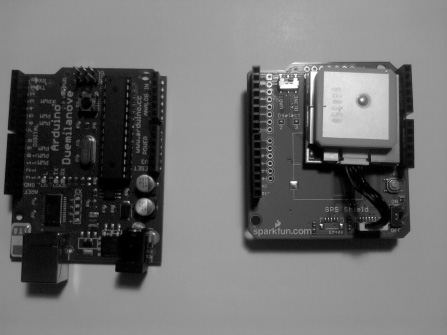
Figure 5-2. Hardware for this project
Configuring the Hardware
Follow these steps to configure the hardware in Project 5-1:
- Connect the GPS shield to the Arduino.
- Make sure the switch that controls the pins the GPS shield uses is switched to DLINE (see Figure 5-12 for an illustration of this process). We use DLINE because it allows us to use the software serial rather than the hardware serial; this is the switch closest to the tx and rx pins on the GPS shield.
- Connect the USB from the Arduino to a computer.
Figure 5-3 illustrates the hardware configuration. In the next section, we will be discussing the software for this project.
![]() Note A hardware serial uses some form of microchip to transfer data bit by bit. A software serial uses interrupts and other software controls to make a virtual serial port; this is useful because the Arduino Duemilanove and UNO only have one serial port, so essentially we can create a couple of serial ports rather than just one.
Note A hardware serial uses some form of microchip to transfer data bit by bit. A software serial uses interrupts and other software controls to make a virtual serial port; this is useful because the Arduino Duemilanove and UNO only have one serial port, so essentially we can create a couple of serial ports rather than just one.
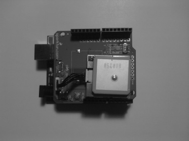
Figure 5-3. Hardware configuration for this project
Writing the Software
We will need to use the NewSoftwareSerial (Thanks Mikal Hart) you learned about in Chapter 2. After that, all we have to do is send the GPS data to the serial monitor. Listing 5-1 provides the code for this project.
Listing 5-1. Writes Raw GPS Data to a Serial Port
#include <NewSoftSerial.h>


NewSoftSerial serial_gps(2,3);


void setup()

{

   serial_gps.begin(4800);


   Serial.begin(9600);


   Serial.print("
RAW GPS DATA
");


}


void loop()

{

 while (serial_gps.available() > 0)

    {

       int c = serial_gps.read();

       Serial.print(c, BYTE);

    }
}
The first thing this code does is include the NewSoftwareSerial header file so that we can use the NewSoftwareSerial library. After that, we create an instance of the NewSoftwareSerial with this code:
NewSoftSerial serial_gps(2,3);
Next, we enter the setup structure where we begin both the software serial and the hardware serial, and then we write “Raw GPS Data.” Then we enter the loop structure, where we enter a while loop with the condition serial_gps.available > 0. The while loop will run as long as there are bytes at the serial port. Within the while loop, int c is getting the values from the serial read command. Then the data is written to the serial monitor. Now that we have configured the GPS shield to send data to the serial monitor, we can make more complicated applications. In the next project, we will be working with the GPS shield and a monochrome LCD to send latitude and longitude values to the LCD.
Project 5-2: Writing GPS Data to a Monochrome LCD
In this project, we will need to communicate with a monochrome LCD and display latitude and longitude data. We will still need a software serial for this project, but you could use the hardware serial, and everything would work because we are no longer sending data to the serial monitor. You would just need to make sure you do not use the DLINE; instead, you would switch to UART on the GPS shield. In this project, we will be using three libraries: NewSoftwareSerial, TinyGPS, and LiquidCrystal. Now that you know a little about this project, we can see what hardware we will need for this project.
Hardware for This Project
Figure 5-4 shows some of the hardware being used in this project. (Not pictured: solderless breadboard, 9V battery, 9V battery connector, and extra wire.)
- Arduino Duemilanove (or UNO)
- GPS shield
- Monochrome LCD
- 10K potentiometer
- Solderless breadboard
- 9V battery
- 9V battery connector
- Extra wire
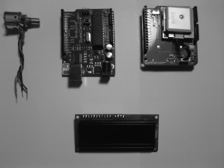
Figure 5-4. Hardware for this project
Configuring the Hardware
To configure the hardware in Project 5-2, follow these steps:
- Connect the GPS shield to the Arduino.
- Connect the Monochrome LCD to the solderless breadboard.
- Connect power (+5V) to pin 2 on the LCD and ground to pin 1 on the LCD.
- Connect the 10K potentiometer's middle wiper (middle wire on pot) to pin 3 on the LCD; the other two wires are connected to power (+5V) and ground.
- Connect the RS, R/W, E, and bus lines from the Arduino to the LCD. We will start with the RS pin. The RS pin is connected to digital pin 7, the R/W pin is connected to ground, the E pin is connected to digital pin 8, and DB7–DB4 are connected to digital pins 12–9 on the Arduino.
- Connect power (+5V) to pin 15 on the LCD and ground to pin 16 on the LCD.
Figure 5-5 illustrates the hardware configuration for this project.
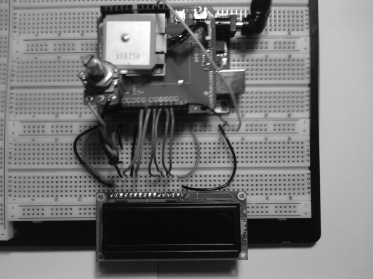
Figure 5-5. Hardware configuration for this project
Writing the Software
The software will need to communicate with the software serial and the monochrome LCD. It will then have to write longitude and latitude to the display in a user-friendly fashion. Listing 5-2 introduces the code for this project.
Listing 5-2. Write latitude and longitude data to monochrome LCD
// include the library code:

#include <LiquidCrystal.h>

// includes the NewSoftwareSerial Library

#include <NewSoftSerial.h>

// include TinyGPS library

#include <TinyGPS.h>


// create an instance of the TinyGPS object

TinyGPS gps;


// initializes the soft serial port

NewSoftSerial nss(2,3);


// initialize the library with the numbers of the interface pins

LiquidCrystal lcd(7,8,9,10,11,12);


void gpsData(TinyGPS &gps);


void setup()

{

   nss.begin(4800);
   // set up the LCD's number of columns and rows:

   lcd.begin(16, 2);

   lcd.clear();


}


void loop()

{


 while(nss.available())   // Makes sure data is at the Serial port

 {

    int c = nss.read();

    if(gps.encode(c))     // New valid sentence?

    {

      gpsData(gps);       // Write data to the LCD

    }

 }


}


void gpsData(TinyGPS &gps)

{

  // Initialize Longitude and Latitude to floating-point numbers

  float latitude, longitude;


  // Get longitude and latitude

  gps.f_get_position(&latitude,&longitude);


  // Set cursor to home (0,0)

  lcd.home();

  // Print "lat: " to LCD screen

  lcd.print("lat:   ");

  // Prints latitude with 5 decimal places to LCD screen

  lcd.print(latitude,5);


  // Sets the cursor to the second row

  lcd.setCursor(0,1);

  // Print "long: " to LCD screen

  lcd.print("long: ");

  // Prints longitude with 5 decimal places to LCD screen

  lcd.print(longitude,5);


}
The first thing this code does is include all of the libraries that the code needs to use. They are the LyquidCrystal library, NewSoftSerial library, and TinyGPS library. After that, we create an instance of TinyGPS, NewSoftSerial, and LyquidCrystal. Then we create a functional prototype called gpsData that has the arguments for the GPS data. We then enter the setup structure, which begins the software serial and the LCD; it also clears the LCD. Next we enter the loop structure. In the loop structure, we first see whether there is any data on the software serial port; if there is, it enters an If statement that has the argument gps.encode(c);. This argument makes sure we have a valid GPS sentence. Finally, we enter the subroutine gpsData. In gpsData() we write the longitude and latitude data to the monochrome LCD.
Now that we can display GPS data on a monochrome LCD, we can add onto our existing hardware and code to make a car finder with the GPS shield and the monochrome LCD.
Project 5-3: Creating a Car Finder
While this project might not find you a new car, it can find your car if you left it in a massive parking lot. This project will need to use some extra digital pins for a push button and a switch; we will use these to interface with the menu we create on the LCD. Let's first take a look at the hardware for this project.
Hardware for This Project
Figure 5-6 shows some of the hardware being used in this project. (Not pictured: solderless breadboard, 9V battery, 9V battery connector, and extra wire.)
- Arduino Duemilanove (or UNO)
- GPS shield
- Monochrome LCD
- Toggle switch
- Normally off push button
- 10K potentiometer
- Solderless bread board
- Extra wire
- 9V battery
- 9V battery connector
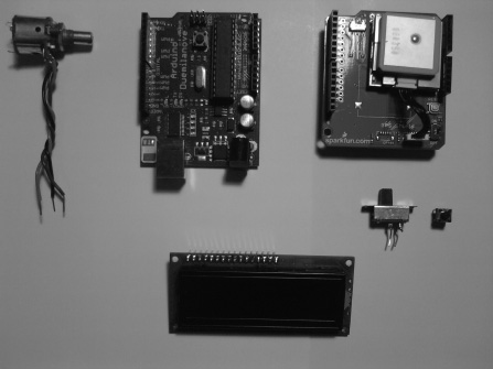
Figure 5-6. Hardware for this project
Configuring the Hardware
To configure the hardware in Project 5-3, follow these steps:
- Connect the GPS shield to the Arduino.
- Connect the Monochrome LCD to the solderless breadboard.
- Connect power (+5V) to pin 2 on the LCD and ground to pin 1 on the LCD.
- Connect the 10K potentiometer's middle wiper (middle wire on pot) to pin 3 on the LCD; the other two wires are connected to power (+5V) and ground.
- Connect the RS, R/W, E, and bus lines from the Arduino to the LCD. We will start with the RS pin. The RS pin is connected to digital pin 7, the R/W pin is connected to ground, the E pin is connected to digital pin 8, and DB7–DB4 are connected to digital pins 12–9 on the Arduino.
- Connect power (+5V) to pin 15 on the LCD and ground to pin 16 on the LCD.
- Now that the LCD is connected, we need to connect the switch and normally off push button:
- Connect the switch and push button to the solderless breadboard.
- Connect one pin of the switch and push button to ground.
- Connect the other pin on the switch to digital pin 5 on the Arduino.
- Connect the other pin on the push button to digital pin 6 on the Arduino.
Figure 5-7 illustrates the hardware configuration for this project.
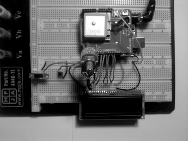
Figure 5-7. Hardware configuration for this project
Writing the Software
The software for this project is a lot like the software from the previous project. The only difference is that we filter a lot of the data; we are using a push button and a switch. The switch is used to control a menu, and the push button is used to store the GPS position of a car in a parking lot. We also do limit testing to tell the person that their car is near or that they need to keep looking. Listing 5-3 is the code for this project.
Listing 5-3. ArduinoCarFinder.pde
// include the library code:

#include <LiquidCrystal.h>

// includes the NewSoftwareSerial Library

#include <NewSoftSerial.h>

// include TinyGPS library

#include <TinyGPS.h>


// create an instance of the TinyGPS object

TinyGPS gps;


// initializes the soft serial port

NewSoftSerial nss(2,3);


// initialize the library with the numbers of the interface pins

LiquidCrystal lcd(7,8,9,10,11,12);
// set up buttons

int button1 = 5;

int button2 = 6;


float latVal = 0;

float longVal= 0;


int buttonVal1 = 0;

int buttonVal2 = 0;


int buttonCount = 0;

int numCount = 0;


void gpsData(TinyGPS &gps);


void setup()

{

   nss.begin(4800);


   pinMode(button1, INPUT);

   pinMode(button2, INPUT);


   digitalWrite(button1, HIGH);

   digitalWrite(button2, HIGH);


   // set up the LCD's number of columns and rows:

   lcd.begin(16, 2);

   lcd.clear();

   lcd.home();

   lcd.print("Arduino");

   lcd.setCursor(0,1);

   lcd.print("Car Finder");

   delay(3000);

   lcd.clear();


}


void loop()

{

 while(nss.available())   // Makes sure data is at the Serial port

 {

    int c = nss.read();

    if(gps.encode(c))     // New valid sentence?

    {

      gpsData(gps);       // Write data to the LCD

    }

 }

}
void gpsData(TinyGPS &gps)

{

  // Initialize Longitude and Latitude to floating-point numbers

  float latitude, longitude;


  // Get longitude and latitude

  gps.f_get_position(&latitude,&longitude);


  buttonVal1 = digitalRead(button1);

  buttonVal2 = digitalRead(button2);


  if (buttonVal2 == LOW)

  {

    buttonCount++;

  }


  if(buttonVal1 == LOW)

  {

    switch (buttonCount)

      {

       case 1:

       if (numCount <= 0)

       {

         gps.f_get_position(&latitude,&longitude);

         latVal = latitude;

         longVal = longitude;

         delay(250);

         numCount++;

       }

       else if (numCount > 0)

       {

         lcd.home();

         lcd.print("car is here:     ");

         delay(2000);

         lcd.clear();

         lcd.home();

         lcd.print("Lat:   ");

         lcd.print(latVal,5);

         lcd.setCursor(0,1);

         lcd.print("Long: ");

         lcd.print(longVal,5);

         delay(5000);

         lcd.clear();


       }

       break;

       case 2:

       lcd.clear();

       lcd.home();

       lcd.print("Reset Car loc");

       lcd.setCursor(0,1);
       lcd.print("keep holding");

       delay(5000);

       lcd.clear();

       break;

       default:

       buttonCount = 0;

       numCount = 0;

       break;


      }

  }


  if(buttonVal1 == HIGH)

  {

    lcd.home();

    lcd.print("You are here:   ");

    delay(2000);

    lcd.clear();

    // Set cursor to home (0,0)

    lcd.home();

    // Print "lat: " to LCD screen

    lcd.print("lat:   ");

    // Prints latitude with 5 decimal places to LCD screen

    lcd.print(latitude,5);


    // Sets the cursor to the second row

    lcd.setCursor(0,1);

    // Print "long: " to LCD screen

    lcd.print("long: ");

    // Prints longitude with 5 decimal places to LCD screen

    lcd.print(longitude,5);

    delay(5000);

    lcd.clear();

    if (longitude <= longVal + 0.00010 && longitude >= longVal - 0.00010 && latitude <= latVal + 0.00010 &&   latitude >= latVal - 0.00010)

     {

      lcd.clear();

      lcd.home();

      lcd.print("You should see  ");

      lcd.setCursor(0,1);

      lcd.print("your car");

      delay(2000);

      lcd.clear();


    }

    else

    {

      lcd.clear();

      lcd.home();

      lcd.print("Keep Looking    ");
      delay(1000);

      lcd.clear();

    }


  }


}
This code has a lot of software we have already discussed, so I am going to go over the new pieces that may look a little different. The first piece of code is at the very beginning of the program. It looks like this:
void gpsData(TinyGPS &gps);
This is a functional prototype; we have to declare it at the beginning of the program because the compiler needs to know it is there. After that, we don't see new code until we get to the function gpsData; in this function we initialize the longitude and latitude variables and set them as arguments in the f_get_position() function. Then we set buttonVal1 and buttonVal2 to the digital reads on pins 5 and 6. Next we create an if statement that controls the buttonCount value. After that, we check whether buttonVal1 is “LOW.” If it is, we enter the switch statement that controls a car's GPS position in a parking lot. The first case writes the value of the GPS location into latVal and LongVal. The second case is there to notify the user that they need to keep holding the push button in order to reset the car's GPS location. The third case sets numCount to 0 and buttonCount to 0. The next if statement checks whether buttonVal1 is “HIGH.” If it is, we write the current latitude and longitude values to the monochrome LCD. Also within this if statement is a limit test (the nested if statement). This if statement is checking whether you are close to your car. If you are within 0.00010 of your car, the LCD will display “You should see your car.” If it is not within 0.00010, then the LCD will display “Keep looking.”
To use this project, you will need to switch to car mode (off) you should then see on the LCD the longitude and latitude values. Then press the button, and the LCD should display “Car is here” and then the location of your car. Next flip the switch to the locator mode (On). The LCD should display “You are here” and then the longitude and latitude position of where you are. To reset your car's location, switch back to car mode (off) and hold the push button until a blank LCD screen appears. Then you should be able to save a new GPS location.
Now that we have worked extensively with the TinyGPS library, we are going to work with the SdFat library to log GPS data to file. This will be the discussion of the next project.
![]() Note When resetting a car's GPS location, you need to hold the push button down until “Car is here” comes back onto the LCD.
Note When resetting a car's GPS location, you need to hold the push button down until “Car is here” comes back onto the LCD.
Project 5-4: GPS Data Logger
In this project, we will need to utilize the SdFat library and the NewSoftSerial library. You will also learn a new function that will allow us to use floating-point numbers. We will need all of this to create a stand-alone GPS data logger. The next section will discuss the hardware we will need for this project.
Hardware for This Project
Figure 5-8 shows some of the hardware being used in this project. (Not pictured: USB cable, 9V battery, and 9V battery connector.)
- Arduino Duemilanove (ATMega328 version) (or UNO)
- GPS shield
- microSD shield
- USB cable (or 9V battery)
- 9V battery connector if 9V is used
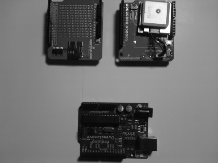
Figure 5-8. Hardware for this project
Configuring the Hardware
The first thing we will do for this project is attach the microSD shield to the Arduino. Next attach the GPS shield to the microSD shield. Figure 5-9 illustrates the hardware configuration for this project.
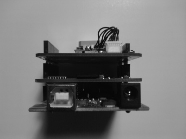
Figure 5-9. Hardware configuration for this project
Writing the Software
For this project to work correctly, we need to utilize the SdFat library, the NewSoftSerial library, and the TinyGPS library. We also need to use a function that will allow us to write the longitude and latitude data to the microSD card; this function is called the printFloat() function. This function will convert a floating-point variable to a string, which will allow us to send the longitude and latitude data to a microSD card. Listing 5-4 shows the code for this project.
Listing 5-4. Send Longitude and Latitude Data to a microSD Card
//Add the SdFat Libraries

#include <SdFat.h>

#include <SdFatUtil.h>

#include <ctype.h>

#include <NewSoftSerial.h>

#include <TinyGPS.h>


NewSoftSerial nss(2,3);

TinyGPS gps;


void printFloat(double number, int digits); // function prototype for printFloat function


//Create the variables to be used by SdFat Library

Sd2Card card;

SdVolume volume;

SdFile root;

SdFile file;


char name[] = "GPSData.txt";     // holds the name of the new file

char LatData[50];                // data buffer for Latitude
char LongData[50];               // data buffer for longitude


void setup(void)

{

  Serial.begin(9600);        // Start a serial connection.

  nss.begin(4800);           // Start soft serial communication

  pinMode(10, OUTPUT);       // Pin 10 must be set as an output for the SD communication to

                             // work.

  card.init();               // Initialize the SD card and configure the I/O pins.

  volume.init(card);         // Initialize a volume on the SD card.

  root.openRoot(volume);     // Open the root directory in the volume.

}


void loop(void)

{


  while (nss.available() > 0)

  {

    int c = nss.read();


    // Initialize Longitude and Latitude to floating-point numbers

    if(gps.encode(c))     // New valid sentence?

    {

      float latitude, longitude;


      // Get longitude and latitude

      gps.f_get_position(&latitude,&longitude);


      // Print "lat: " to LCD screen

      Serial.print("lat:   ");

      // Prints latitude with 5 decimal places to the serial monitor

      Serial.println(latitude,5);


      // Print "long: " to the serial monitor

      Serial.print("long: ");

      // Prints longitude with 5 decimal places to the serial monitor

      Serial.println(longitude,5);


     delay(500);


     file.open(root, name, O_CREAT | O_APPEND | O_WRITE);    // Open or create the file 'name'

                                              // in 'root' for writing to the end of the file.

     file.print("Latitude: ");

     printFloat(latitude, 6);

     file.println("");

     file.print("Longitude: ");

     printFloat(longitude, 6);

     file.println("");

     file.close();            // Close the file.

     delay(1000);     // Wait 1 second

    }
  }


}


void printFloat(double number, int digits)

{

  // Handle negative numbers

  if (number < 0.0)

  {

     file.print('-'),

     number = -number;

  }


  // Round correctly so that print(1.999, 2) prints as "2.00"

  double rounding = 0.5;

  for (uint8_t i=0; i<digits; ++i)

    rounding /= 10.0;


  number += rounding;


  // Extract the integer part of the number and print it

  unsigned long int_part = (unsigned long)number;

  double remainder = number - (double)int_part;

  file.print(int_part);


  // Print the decimal point, but only if there are digits beyond

  if (digits > 0)

    file.print(".");


  // Extract digits from the remainder one at a time

  while (digits-- > 0)

  {

    remainder *= 10.0;

    int toPrint = int(remainder);

    file.print(toPrint);

    remainder -= toPrint;

  }

}
The first thing this code does is include all of the headers so that we can use the libraries that the program needs. Next we create a function prototype so that we can use the printFloat() function. After that, we create instances of Sd2Card, SdVolume, and SdFile. Then we enter the setup structure where we begin serial communication and soft serial communication; we also set digital pin 10 to an output. Then we initialize the microSD card. Next we enter the loop structure. In the loop structure, we first create a while loop that checks whether the software serial has data. If it does, we add the data from the software serial to int c. We then use an if statement to make sure int c is a valid GPS sentence. After that, we send the parsed GPS data to the serial monitor (serial port). The next bit of code opens or creates a file and appends data to the end of the file. Finally, we use the printFloat() function to convert the LatData and LongData to strings and then write LatData and LongData to the microSD card in this format:
Lat:  **.******

Long: **.******
You can use this GPS data logger stand-alone so that you can take it for a ride in a car or while you are riding your bike.
Now that we understand the basics of GPS communication, we can return to the company and see whether they have any project that needs our newfound knowledge. It just so happens that they need us to add GPS communication to the previous chapter's robot. The first thing we need to do is gather the requirements and create the requirements document.
Requirements Gathering and Creating the Requirements Document
The customer wants to add an accessory onto the robot from Chapter 4. They want a field robot that has the ability to send the GPS location of the robot and log it to a text file. They will no longer need the color LCD because it is an accessory to the robot as well. They want to send a separate command to the robot in order to get the latitude and longitude data from GPS (this robot adds on to the robot from Chapter 3 and Chapter 4). The latitude and longitude should have this format:
Lat:   **.******

Long:  **.******
They still want the motors controlled by serial communication (USB wire).
Now that we have our notes from the meeting, we can compile them into a requirements document.
Hardware
Figure 5-10 shows some of the hardware being used in this project. (Not pictured: USB cable and 9V battery.)
- Arduino Duemilanove (ATMega328 version)(or UNO)
- GPS shield
- microSD shield
- 512MB microSD card and card reader
- Chassis from previous robot
- USB cable
- 9V battery
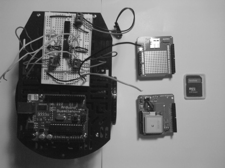
Figure 5-10. Hardware for this project
Software
The following requirements need to be met for the software of this project:
- Display latitude and longitude GPS data in this format:
Lat:   **.******

Long: **.****** - Write latitude and longitude to text file.
- Use NewSoftSerial library.
- Use TinyGPS library.
- Use SdFat library.
- Remove color LCD code.
Now that we have our hardware and software requirements, we can add to the flowchart we created in Chapter 3. Figure 5-11 shows the flowchart for this project.
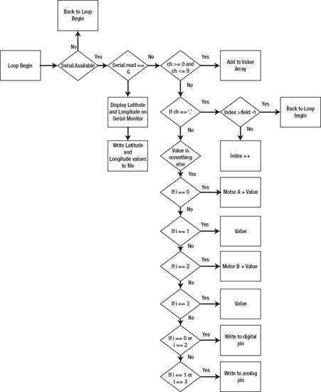
Figure 5-11. Flowchart for this project
Configuring the Hardware
The first thing we want to do is configure the GPS shield so that it uses DLINE and not UART (DLINE will use digital pins 2 and 3 for a software serial, and UART will use digital pins 0 and 1 for a hardware serial). Figure 5-12 illustrates this process.
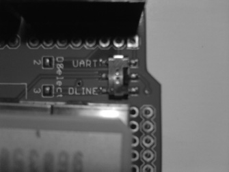
Figure 5-12. Select DLINE on GPS shield
To configure the hardware in this project, follow these steps:
- Connect the microSD shield to the Arduino.
- Connect the GPS Shield to the microSD shield.
- Attach the H-bridge pin 1 to digital pin 5 on the Arduino, attach pin 7 on the H-bridge to digital pin 4 on the Arduino, attach pin 9 on the H-bridge to digital pin 6 on the Arduino, and attach pin 10 on the H-bridge to digital pin 7 on the Arduino.
- Connect H-bridge to power (+5V) and ground on the Arduino.
Figure 5-13 illustrates the hardware configuration for this project.
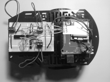
Figure 5-13. Hardware configuration for this project (“H” stands for H-bridge pin and “A” stands for Arduino pin)
The next section will discuss the software we will need to write in order to meet the requirements the company has given us.
Writing the Software
Now that the hardware is configured, we need to write some software so that the GPS data will be parsed into latitude and longitude, then printed to the serial monitor, and finally written to a text file whenever the user enters “G” into the serial monitor. The latitude and longitude data also has to be in a format that the user can understand. Here is the format:
Lat:   **.******

Long:  **.******
Listing 5-5 presents the code for this project.
Listing 5-5. Send GPS location to a microSD card and control motors through the Serial Monitor
#include <SdFat.h>

#include <SdFatUtil.h>

#include <ctype.h>


#include <TinyGPS.h>


#include <NewSoftSerial.h>


TinyGPS gps;


NewSoftSerial nss(2,3);
void printFloat(double number, int digits); // function prototype for printFloat function


int numCount = 0;


const int fields = 4; // how many fields are there? right now 4

int motorPins[] = {4,5,7,6}; // Motor Pins

int index = 0;        // the current field being received

int values[fields];   // array holding values for all the fields


Sd2Card card;

SdVolume volume;

SdFile root;

SdFile file;


char name[] = "GPSData.txt";     // holds the name of the new file

char LatData[50];                // data buffer for Latitude

char LongData[50];


void setup()

{

  Serial.begin(9600); // Initialize serial port to send and receive at 9600 baud

  nss.begin(4800);    // Begins software serial communication


  pinMode(10, OUTPUT);       // Pin 10 must be set as an output for the SD communication to

                             // work.

  card.init();               // Initialize the SD card and configure the I/O pins.

  volume.init(card);         // Initialize a volume on the SD card.

  root.openRoot(volume);


  for (int i; i <= 3; i++)        // set LED pinMode to output

  {

    pinMode(motorPins[i], OUTPUT);

    digitalWrite(motorPins[i], LOW);

  }


  Serial.println("The Format is: MotoADir,MotoASpe,MotorBDir,MotoBSpe
");

}


void loop()

{


  if( Serial.available())

  {

    char ch = Serial.read();


    if (ch == 'G') // if Serial reads G

    {

      digitalWrite(motorPins[0], LOW);

      digitalWrite(motorPins[2], LOW);

      analogWrite(motorPins[1], 0);

      analogWrite(motorPins[3], 0);
      while (numCount == 0)

      {

        if (nss.available() > 0) // now gps device is active

        {

          int c = nss.read();

          if(gps.encode(c))     // New valid sentence?

          {


            // Initialize Longitude and Latitude to floating-point numbers

            float latitude, longitude;


            // Get longitude and latitude

            gps.f_get_position(&latitude,&longitude);


            Serial.print("Lat:   ");

            // Prints latitude with 5 decimal places to the serial monitor

            Serial.println(latitude,7);


            Serial.print("long: ");

            // Prints longitude with 5 decimal places to the serial monitor

            Serial.println(longitude,7);


            file.open(root, name, O_CREAT | O_APPEND | O_WRITE);    // Open or create the file

                                                                    // 'name'

                                                                    // in 'root' for writing

                                                                    // to the

                                                                    // end of the file.

            file.print("Latitude: ");

            printFloat(latitude, 6);

            file.println("");

            file.print("Longitude: ");

            printFloat(longitude, 6);

            file.println("");

            file.close();    // Close the file.

            delay(1000);     // Wait 1 second


            numCount++;

          }

        }

      }

    }

    else if(ch >= '0' && ch <= '9') // If the value is a number 0 to 9

    {

      // add to the value array

      values[index] = (values[index] * 10) + (ch - '0'),

    }

    else if (ch == ',') // if it is a comma

    {

      if(index < fields -1) // If index is less than 4 - 1…

        index++; // increment index

    }

    else
    {


      for(int i=0; i <= index; i++)

      {


        if (i == 0 && numCount == 0)

        {

          Serial.println("Motor A");

          Serial.println(values[i]);

        }

        else if (i == 1)

        {

          Serial.println(values[i]);

        }

        if (i == 2)

        {

          Serial.println("Motor B");

          Serial.println(values[i]);

        }

        else if (i == 3)

        {

          Serial.println(values[i]);

        }


        if (i == 0 || i == 2)  // If the index is equal to 0 or 2

        {

          digitalWrite(motorPins[i], values[i]); // Write to the digital pin 1 or 0

          // depending what is sent to the arduino.

        }


        if (i == 1 || i == 3) // If the index is equale to 1 or 3

        {

          analogWrite(motorPins[i], values[i]);  // Write to the PWM pins a number between

          // 0 and 255 or what the person has enter

          // in the serial monitor.

        }


        values[i] = 0; // set values equal to 0


      }


      index = 0;

      numCount = 0;

    }


  }


}


void printFloat(double number, int digits)

{
  // Handle negative numbers

  if (number < 0.0)

  {

     file.print('-'),

     number = -number;

  }


  // Round correctly so that print(1.999, 2) prints as "2.00"

  double rounding = 0.5;

  for (uint8_t i=0; i<digits; ++i)

    rounding /= 10.0;


  number += rounding;


  // Extract the integer part of the number and print it

  unsigned long int_part = (unsigned long)number;

  double remainder = number - (double)int_part;

  file.print(int_part);


  // Print the decimal point, but only if there are digits beyond

  if (digits > 0)

    file.print(".");


  // Extract digits from the remainder one at a time

  while (digits-- > 0)

  {

    remainder *= 10.0;

    int toPrint = int(remainder);

    file.print(toPrint);

    remainder -= toPrint;

  }

}
Most of this code is from the previous robot, so I will go over only the new pieces of code that this program has. At the beginning of this program, we include the header files for the NewSoftSerial library, TinyGPS library, and SdFat library. Then we create instances of those libraries with these pieces of code:
TinyGPS gps;


NewSoftSerial nss(2,3);


Sd2Card card;

SdVolume volume;

SdFile root;

SdFile file;
Then we create the file name we will use to store the latitude and longitude data and create the character arrays that will hold the latitude and longitude values. The next piece of new code is not encountered until we get inside the setup structure, where we begin soft serial communication. After that in the loop structure, we see this code at the beginning:
if (ch == 'G') // if Serial reads G

    {
      digitalWrite(motorPins[0], LOW);

      digitalWrite(motorPins[2], LOW);

      analogWrite(motorPins[1], 0);

      analogWrite(motorPins[3], 0);


      while (numCount == 0)

      {

        if (nss.available() > 0) // now gps device is active

        {

          int c = nss.read();

          if(gps.encode(c))     // New valid sentence?

          {


            // Initialize Longitude and Latitude to floating-point numbers

            float latitude, longitude;


            // Get longitude and latitude

            gps.f_get_position(&latitude,&longitude);


            Serial.print("Lat:   ");

            // Prints latitude with 5 decimal places to the serial monitor

            Serial.println(latitude,7);


            Serial.print("long: ");

            // Prints longitude with 5 decimal places to the serial monitor

            Serial.println(longitude,7);


            file.open(root, name, O_CREAT | O_APPEND | O_WRITE);    // Open or create the file

                                                                    // 'name'

                                                                    // in 'root' for writing

                                                                    // to the

                                                                    // end of the file.

            file.print("Latitude: ");

            printFloat(latitude, 6);

            file.println("");

            file.print("Longitude: ");

            printFloat(longitude, 6);

            file.println("");

            file.close();    // Close the file.

            delay(1000);     // Wait 1 second


            numCount++;

          }

        }

      }

    }
This is the main code that we added. The if statement uses the condition that if the serial port reads G, then it needs to set all of the H-bridge pins that are connected to the Arduino to 0 or LOW. Next we use a while loop with the condition numCount == 0 (numCount was initialized at the very beginning of the program; this variable is used to turn on and off the GPS data). If this condition is true, we make sure that there is information waiting on the software serial (nss). If this is true, then we set int c to the value that is on nss. After that, we make sure that we are receiving valid GPS data. If we are receiving valid data, then we parse through the GPS data and print latitude and longitude data to the serial monitor. Then we send latitude and longitude values to a text file and increment the numCount variable. Now that we have written the software, we may have encountered a few bugs. The next section will discuss debugging this project's software.
Debugging the Arduino Software
First, if you copied and pasted the code from the previous project, you may have run into problems that involve the color LCD. Make sure you removed all of the color LCD code, and also if you used some of the code from the monochrome LCD project in the gpsData() function, make sure you change these values from lcd.write() to Serial.write() functions. I also want to go over a good technique to find errors within your code. You can use Serial.write() functions to find out where your code is at a certain time or if it is entering a certain conditional statement or even a loop. Listing 5-6 is an example of using this to make sure that your program is entering a conditional statement before you implement code that may take you hours to fix (probably not hours for this example, but think about how long it would take for thousands of lines).
Listing 5-6. Debugging your code with serial commands
char ch;


void setup()

{

  Serial.begin(9600);


  Serial.println("Entered Setup Structure");

  delay(1000);


}

void loop()

{

  ch = Serial.read();


  if (ch == 'g')

  {

     Serial.println("First If Statement entered");

  }

  else if (ch == 's')

  {

     Serial.println("Second If Statement entered");

  }

  else

  {

     Serial.println("Else Statement entered");

  }

  delay(1000);


}
This type of debugging can be used at the beginning or end of you project. I like to use this debugging technique when trying to figure out whether my architecture is correct. Now that we have debugged the software for this project and gone over a new technique, we can troubleshoot the hardware.
Troubleshooting the Hardware
Well, you also may have run into a few hardware issues with this project. If you did, we will run through a few tips to make this project work correctly. First, if your GPS is not giving you any data, you may want to make sure it is on (we all have done this before) and also make sure you have selected DLINE. Next, make sure that the GPS's LED is blinking. If it is a solid green light, that means the GPS has not found a fix yet; if it is blinking, then it has a fix. Also, you may want to make sure your serial monitor is set to the correct baud rate; in this case, 9600 will do for this project. If you are having problems getting the microSD shield working, make sure you are using a microSD that is no larger than 2GB and that it is formatted to FAT16 or FAT32. If problems persist with the microSD shield, you should contact the shop you bought it from because you may have a soldering problem (this actually happens but not often, though). If your motors are not going in the correct direction, you may need to switch your power and ground on each of the motors (just make sure you are consistent on the H-bridge's motor terminals). Also make sure that all of your wires are connected properly on the solderless breadboard (see Chapter 4's final project). If everything is working and you are having no problems, then move to the next step, which is the finished prototype.
Finished Prototype
Well, this project is now at a stage where everything is working and has been tested thoroughly. Figure 5-14 illustrates the finished prototype.
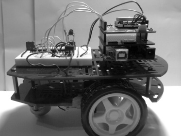
Figure 5-14. Finished prototype
Summary
This chapter has been aimed at getting you ready to experiment with GPS communication. We first ventured into NMEA commands, and I summarized their uses and values. After that we talked about the TinyGPS library and the SdFat library. Also, throughout this chapter, we went over various projects that implement GPS in various ways. They were writing raw GPS data to the serial monitor, writing GPS data to a monochrome LCD, creating a car finder, and creating a GPS data logger. Then we worked on another engineering project that utilized the engineering process and GPS communication. Now that you understand GPS communication, you can make your own projects with the GPS shield.