
C H A P T E R 8
Mature Arduino Engineering: Making an Alarm System Using the Arduino
In this chapter we will be creating various pieces of a motion detecting alarm system using the Arduino. To satisfy our example company’s requirements, the alarm system will track any motion detected throughout the day and store it on a microSD card. The company also wants to have real-time tracking, so the information will need to be displayed on the Serial Monitor.
To do so, we will be learning about a new piece of hardware called the passive infrared (PIR). We will also be using an ultrasonic sensor in order to create a different type of security system. Our preliminary project uses an ultrasonic sensor as a door alarm. This will prep us for the final project, which is to be delivered to the customer. We will use the PIR in order to detect motion that has occurred in a room.
Before we get into the project, though, the next section will discuss the new hardware for this chapter.
![]() Note I would not recommend using these projects as your sole security system. This chapter will introduce you to some prototypes for a security system.
Note I would not recommend using these projects as your sole security system. This chapter will introduce you to some prototypes for a security system.
Hardware Explained: PIR
The PIR will detect changes in infrared radiation; thus, we can use it to detect motion, because the human body does not have a constant temperature. The PIR cannot sense movement unless there is this change in temperature. To use a PIR sensor, connect the signal of the PIR to a digital pin on the Arduino, just as you did with the ultrasonic sensor. Figure 8-1 shows a PIR sensor.
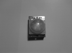
This particular PIR sensor comes from Parallax and has a three-pin configuration (i.e., power, ground, and signal).
That’s it for the new hardware for this chapter—we can move on to a project that will help you get ready for the final project later in this chapter.
Basic Security System
Before we get to the final project, we need to go over a project that will give some basics of a security system. In this project, we will be using an ultrasonic sensor to detect whether a door has been opened. This project will require a large enclosure to mount the ultrasonic sensor. We will also be using the Bluetooth Mate Silver from Sparkfun to send alarm information to the Serial Monitor.
Project 8-1: Door Alarm
In this project, we will be creating a door alarm system. While you can use many different approaches to do this, we are going to use an ultrasonic sensor to make this project sense that a door has been opened. We will also use the microSD shield to datalog how many times the door has been opened. The next section will discuss the hardware for this project.
![]() Note We will be expanding on this project in the next chapter.
Note We will be expanding on this project in the next chapter.
Hardware for This Project
Figure 8-2 shows some of the following hardware being used in this project. (Not pictured: 9V adapter, AC Adapter 9V 650mAh, 9V connector, Velcro, breadboard, and scrap piece of plastic.)
- Arduino Duemilanove (or UNO)
- microSD shield
- 512mb–1GB microSD card
- Ultrasonic sensor (Ping))) from Parallax)
- Ping))) bracket kit from Parrallax
- Bluetooth Mate Silver or BluSmirf
- 9V or AC adapter (9V 650mAh)
- 9V connector (if needed)
- Scrap piece of plastic orenclosure to make the barrier
- Velcro
- Solderless breadboard
- Enclosure to house circuit
- Extra wire
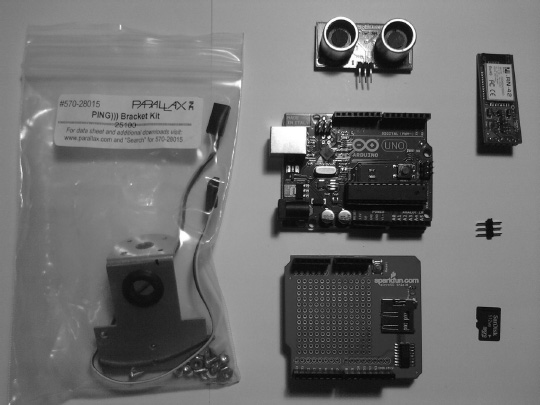
Figure 8-2. Hardware for this project
![]() Note I recommend using an AC adapter for this project, as it will be on for extended periods of time.
Note I recommend using an AC adapter for this project, as it will be on for extended periods of time.
Configuring the Hardware
There are several steps required to configure the hardware for Project 8-1. We will use a dremmel to drill holes into the plastic enclosure. First, we need to configure the enclosure for this project. To do so, follow these steps:
- Using a drill or dramel, drill two holes for screws; these screws will connect the ultrasonic sensor bracket to the top of the enclosure. To figure out where the holes need to go, use a marker and hold the ultrasonic mount to the lid of the enclosure and mark where the screw holes need to be. Figure 8-3 illustrates this process.
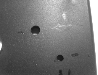
Figure 8-3. Drill holes for the ultrasonic bracket.
- Next, drill a hole in the top so that the ultrasonic sensor’s wire can reach the solderless breadboard inside the enclosure. Figure 8-4 illustrates this process.

Figure 8-4. Drill a hole so the ultrasonic wires can be connected to solderless breadboard.
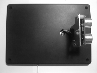
- Now, connect the ultrasonic bracket to the top of the enclosure using the two holes you drilled in the first step. Figure 8-5 illustrates this process.

Figure 8-5. Connect ultrasonic bracket to lid of the enclosure.
- Attach the ultrasonic sensor to the ultrasonic bracket. Figure 8-6 illustrates this process.
- Finally, use a dremel to drill a hole for the power supply. I chose the right back corner for the Arduino, so the right back corner will be where we drill this hole. Figure 8-7 illustrates this process.

Figure 8-7. Drill a hole so that power can be connected to the Arduino.
Now that the enclosure is set up, we need to configure the circuit.
- Connect the microSD Shield to the Arduino.
- Connect the Bluetooth Mate Silver to the solderless breadboard.
- Connect the CTS pin and the RTS pin on the Bluetooth Mate Silver. After that, connect power and ground to the Bluetooth Mate Silver.
- Connect wires to the TX and RX pins on the Bluetooth Mate Silver, as shown in Figure 8-8. (Note that the Bluetooth mate silvers pins are referenced by name, as they have no pin numbers.)
Note Do not connect the TX and RX lines of the Bluetooth Mate Silver until after you have uploaded the code to your Arduino. If you attach the TX and RX pins and attempt to send the scetch (code) to the Arduino you will run into an error and the code will not be uploaded to the Arduino.
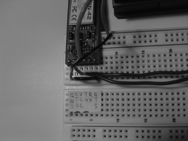
Figure 8-8. Configuration of the Bluetooth Mate Silver
- Connect the ultrasonic senor to the solderless breadboard.
- Connect power (+5V) and ground to the power and ground pins on the ultrasonic sensor.
- Connect digital pin 7 on the Arduino to the signal pin on the ultrasonic sensor. Figure 8-9 illustrates this process.
![]() Note All that is left to do with the hardware configuration is to connect the TX pin on the Bluetooth Mate Silver to the RX pin on the Arduino and the RX pin on the Bluetooth Mate Silver to the TX pin on the Arduino, but we will do that after we have uploaded this project’s code to the Arduino. In the next section, we will be going over the software for this project.
Note All that is left to do with the hardware configuration is to connect the TX pin on the Bluetooth Mate Silver to the RX pin on the Arduino and the RX pin on the Bluetooth Mate Silver to the TX pin on the Arduino, but we will do that after we have uploaded this project’s code to the Arduino. In the next section, we will be going over the software for this project.
Writing the Software
To write this software, we are going to use the SdFat Library in order to write data to a microSD card. Also, we will use serial communication to test that the device is working properly, and to monitor the security system. The ultrasonic sensor will need to check how far away the door is relative to the ultrasonic sensor. Listing 8-1 provides the program for this project.
Listing 8-1. Door Alarm
//Add the SdFat Libraries

#include <SdFat.h>

#include <SdFatUtil.h>


//Create the variables to be used by SdFat Library

Sd2Card card;

SdVolume volume;

SdFile root;

SdFile file;
char name[] = "Data.txt";     // holds the name of the new file

const int pingPin = 7;


void setup()

{

  Serial.begin(115200);      // Start a serial connection.

  pinMode(10, OUTPUT);       // Pin 10 must be set as an output for the SD communication to

                             // work.

  card.init();               // Initialize the SD card and configure the I/O pins.

  volume.init(card);         // Initialize a volume on the SD card.

  root.openRoot(volume);     // Open the root directory in the volume.

}


void loop()

{

  float duration, inches;

  // send  low and high pulse out of the ultrasonic sensor to calculate distance from

  // an object.

  pinMode(pingPin, OUTPUT);

  digitalWrite(pingPin, LOW);

  delayMicroseconds(2);

  digitalWrite(pingPin, HIGH);

  delayMicroseconds(5);

  digitalWrite(pingPin, LOW);


  pinMode(pingPin, INPUT);

  duration = pulseIn(pingPin, HIGH);


  // convert the time into a distance

  inches = duration / 74 / 2;

  delay(500);


  if (inches >= 5)

  {

    Serial.println("Door Open!!"); // send “Door Opened” if distance is reached to the

                                   // Serial Monitor.

    delay(500);

    file.open(root, name, O_CREAT | O_APPEND | O_WRITE);    // Open or create the file 'name'

                                                            // in 'root' for writing to the

                                                            // end of the file.

    file.println("Door Open!!");

    file.close();

  }

  else

  {

    Serial.println("Nothing to Report");

  }


  delay(1000);

}
We first include the header files for the SdFat Library so that we can use the microSD Shield to send data. After that, we create instances of the Sd2Card, SdVolume, and SdFile. Then we create the name of the file that will be written to a microSD card. Next we create a variable that will hold the pin number for the ultrasonic sensor. After that, we enter the Setup Structure; here, we initialize serial communication. We set pin 10 to an output and initialize the card and volume in order to use the microSD Shield. Next, we enter the Loop Structure; here, we initialize duration and inches to be floating point numbers. Then we send a pulse out of the ultrasonic sensor and receive the pulse back, and next we calculate duration and convert it to inches. After that, we have a conditional If-Else statement that will print to the Serial Monitor “Door Open!!” If the ultrasonic sensor detects a distance greater than five inches, it will also write “Door Open!!” to the microSD card. If the door has not been opened, the Serial Monitor will display “Nothing to report.”
Once you upload this program to the Arduino, connect the Bluetooth Mate Silver’s TX and RX pins to the Arduino, as described in the Note at the end of the “Configuring the Hardware” section.
Figure 8-10 illustrates the Bluetooth Mate silver connected to the Arduino.
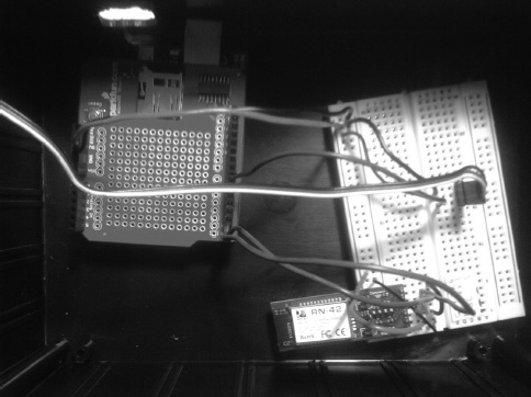
Figure 8-10. Bluetooth Mate Silver’s TX and RX pins connected to the Arduino’s TX and RX pins
To use this device, you need to put it to the side of a door. When the door is opened, it will read that the door has been opened. This project can be tested by simply putting your hand less then five inches away from the ultrasonic sensor and moving it at a distance greater than five inches and you should see “Door Opened!!” on the Serial Monitor. To make the distance great all you need to do is change the If Statement if (inches >= 5) to a different number, for example: if (inches >= 9). Figure 8-11 illustrates the door alarm in action.
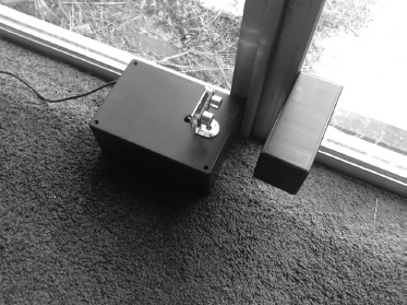
Figure 8-11. Project in action
Now that we have completed this project, we can contact the company again and see if it has a need for any security systems. It just so happens that it does, and we have set up a meeting to go in and hear the requirements. Like with every final project, we need to start with requirements gathering and creating the requirements document.
Requirements Gathering and Creating the Requirements Document
The company has several requirements for a motion detecting alarm system controlled by the Arduino. The motion detector will need to keep track of motion detected throughout the day and stored on a microSD card. The company only wants to write to the microSD card when motion has been detected. The company also wants to have real-time tracking, so the information will need to be displayed on the Serial Monitor. If motion is detected, this will be printed to the Serial Monitor and the microSD card: “Motion Detected!!” If no motion has been detected, this will be printed to the Serial Monitor: “Nothing to Report.” Now that we have gathered our notes, we can create a requirements document that will guide us through the rest of this project.
Hardware
Figure 8-12 shows some of the following hardware being used in this project. (Not pictured: AC adapter, 9V battery, 9V battery connector.)
- Arduino Duemilanove (or UNO)
- microSD shield
- 512mb –1GB microSD card
- PIR sensor
- Bluetooth Mate Silver
- Three terminal extender (included with the Ping))) bracket kit from Parallax)
- Medium size solderless breadboard
- AC adapter (9V 650mAh) or 9V battery
- 9V battery connector if you are using a 9V battery
- Extra wire
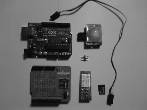
Figure 8-12. Hardware for this project
Software
These are the software requirements for this project:
- Use digital IO to check whether motion has been detected.
- Send data to microSD card when motion has been detected.
- Write to the Serial Monitor when motion is detected, and if motion is not detected, write “Nothing to Report” to the Serial Monitor.
Now that we have the requirements for this project laid out in an understandable fashion, we can create a flowchart that will help us create the software for this project. Figure 8-13 illustrates the flowchart for this project.
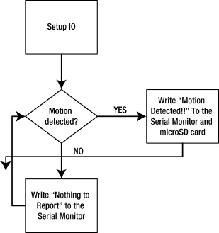
Figure 8-13. Flowchart for this project
The next section will discuss the hardware configuration for this project.
Configuring the Hardware
The following steps will guide you through the hardware configuration for this project.
- Connect the Bluetooth Mate Silver to the solderless breadboard.
- Connect the PIR to the three-pin terminal extender.
- Connect the other end of the extender to a three-pin male header.
- Connect the PIR to the solderless breadboard.
Figure 8-14 illustrates these processes.
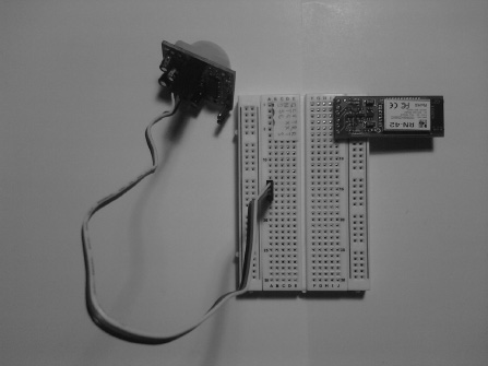
Figure 8-14. Attach the Bluetooth Mate Silver and the PIR sensor to the solderless breadboard.
Now we need to connect power and ground to our circuits. Follow these steps:
- Connect power and ground to the solderless breadboard.
- Connect power (+5V) to the Bluetooth Mate Silver and to the PIR.
- Connect ground to the Bluetooth Mate Silver and to the PIR. Figure 8-15 illustrates these processes.
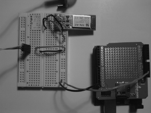
Figure 8-15. Connect power (+5V) and ground to Bluetooth Mate Silver and PIR sensor.
- Connect digital pin 6 from the Arduino to the PIR’s signal pin.
- Connect the RTS pin and the CTS pin on the Bluetooth Mate Silver together. We will not connect the RX and TX pin on the Bluetooth Mate Silver to the Arduino until we upload the Arduino sketch to the Arduino.
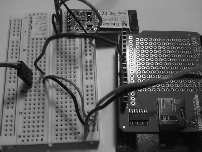
Figure 8-16 shows the complete hardware configuration for this project.
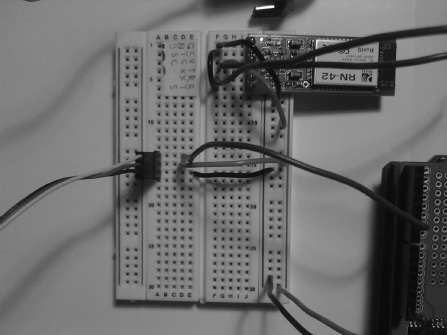
Figure 8-16. Connect PIR sensor to digital pin 6 on the Arduino.
Now that the hardware is configured, we can work on the software requirements for this project. The next section will discuss the software necessary to complete this project.
Writing the Arduino Software
The software will need to communicate with the PIR sensor, and because it acts like a switch, it will be very simple to implement it into our code. Also, we will need to write data to a microSD card and to the Serial Monitor. Listing 8-2 provides the code for this project.
Listing 8-2. Using a PIR to Detect Motion— If Motion Is Detected, It Will Write to the Serial Monitor.
// header files to use microSD shield

#include <SdFat.h>

#include <SdFatUtil.h>

//Create the variables to be used by SdFat Library

Sd2Card card;

SdVolume volume;

SdFile root;

SdFile file;


char name[] = "Data.txt";


int PIRpin = 6;

int PIRval = 0;


void setup()
{

  Serial.begin(115200);      // initalize serial communication

  pinMode(PIRpin, INPUT);

  pinMode(10, OUTPUT);       // Pin 10 must be set as an output for the SD communication to

                             // work.

  card.init();               // Initialize the SD card and configure the I/O pins.

  volume.init(card);         // Initialize a volume on the SD card.

  root.openRoot(volume);     // Open the root directory in the volume.


}


void loop()

{

  PIRval = digitalRead(PIRpin);


  if(PIRval == HIGH) // if motion is detected

  {

    Serial.println("Motion Detected!!");

    delay(500);

    file.open(root, name, O_CREAT | O_APPEND | O_WRITE);    // Open or create the file 'name'

                                                            // in 'root' for writing to the

                                                            // end of the file.

    file.println("Motion Detected!!");

    file.close();                                           // Close the file.

    delay(500);

  }

  else

  {

    Serial.println("Nothing to Report");  // sends “Nothing to Report” to the Serial

                                          // Monitor.

    delay(500);

  }


}
First we include the headers so that we can send data to the microSD card. After that, we create instances of the variables necessary for the SdFat Library. Next we initialize the PIR pin on the Arduino. Then we enter the Setup Structure. Here, we start serial communication, set up the PIR_pin variable to an output, and start communicating with the microSD shield. After that, we enter the Loop Structure. Here, we set the PIRval equal to the reading on digital pin 6. Then we have a conditional If-Else-Statement that will control what data is written to the Serial Monitor or the microSD card.
If the PIRval is “HIGH,” “Motion Detected!!” will be written to the Serial Monitor and the microSD card. Otherwise, “Nothing to Report” will be written to the Serial Monitor. Now that the software is completed, we can upload it to the Arduino. After we have uploaded the software to the Arduino, we can connect the TX pin on the Bluetooth Mate Silver to the RX pin on the Arduino, and the RX pin on the Bluetooth Mate Silver to the TX pin on the Arduino.
Now that the software requirements have been completed, we are ready to figure out any errors that we may have encountered. The next sections will discuss debugging the software and troubleshooting the hardware. Figure 8-17 illustrates connecting the RX and TX wires.
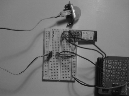
Figure 8-17. TX and RX pins on Bluetooth Mate Silver connected to TX and RX pins on Arduino.
Debugging the Arduino Software
This program was pretty straightforward. If you did run into an error, it may have been a syntax error; make sure you have all variables declared properly, and make sure that all of the statements in the program have a semicolon at the end of them. If you are still having trouble with the code, copy and paste my code into the Arduino IDE. If you are still having issues, it may be due to a library not being installed correctly. Make sure that the library files are all stored in the Arduino-022->Libraries folder. Now that we have debugged our software, we can focus on troubleshooting the hardware.
Troubleshooting the Hardware
You may have had some trouble configuring the hardware. One problem may be that you did not connect the RTS and the CTS pins together. Also make sure you only connect the RX and TX pins on the Bluetooth Mate Silver to the Arduino after you have uploaded the code to the Arduino through a USB cord.
Finished Prototype
Now that we have successfully met all the requirements for this project, we can submit the finished prototype to the company. Figure 8-18 illustrates the finished prototype.
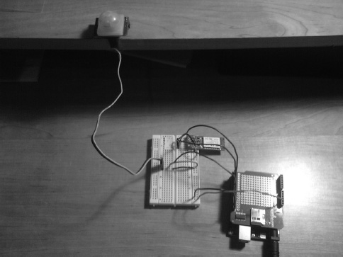
Figure 8-18. Project in action
Summary
We have gone over a few things in this chapter. First, we went over the new hardware we would be using in this chapter. After that, we introduced the first project of this chapter to get us ready for the final project. We then built a door alarm that senses whether a door is open or closed. Next we went through the engineering process to create a motion detection system for a company. There are always ways of making projects better and this project is no different, for example: you could add a real time clock to the project to get the exact time in which a motion was detected, or you may want to take a picture when motion has been detected, so there are many ways to make this project more advanced.