In Chapter 1, Setting Up Your Development Environment, we went through the essentials of the Python ecosystem, virtual environments, and package management and set up your Raspberry Pi for development and GPIO interfacing. In this chapter, we will begin our journey in Python and IoT.
What we cover in this chapter will lay the foundations and give us a working point of reference for the more advanced content that we'll cover in later chapters. We will learn to create a simple electrical circuit with a button, resistor, and LED (or light-emitting diode) and explore alternative ways to interact with the button and LED with Python. We will then proceed to create and discuss a complete end-to-end IoT program to control the LED over the internet and complete this chapter by looking at ways that you can extend the program.
In this chapter, we will cover the following topics:
- Creating a breadboard prototype circuit
- Reading an electronic schematic diagram
- Exploring two ways to flash a LED in Python
- Exploring two ways to integrate a push button in Python
- Creating your first IoT program
- Extending your IoT program
Technical requirements
To perform the exercises in this chapter and throughout this book, you will need the following:
- Raspberry Pi 4 Model B. A 1 GB RAM version will be adequate to run our examples. If you are working directly on your Raspberry Pi versus a Secure Shell (SSH) session; for example, more RAM is recommended to improve the Raspbian Desktop experience and responsiveness.
- You will need Raspbian OS Buster (with desktop and recommended software).
- You will need a minimum of Python version 3.5.
These requirements are what the code examples in this book are based on. It's reasonable to expect that the code examples should work without modification on a Raspberry Pi 3 Model B, Raspberry Pi Zero W, or a different version of Raspbian OS as long as your Python version is 3.5 or higher.
You will find this chapter's source code in the chapter02 folder in the GitHub repository available at the following URL: https://github.com/PacktPublishing/Practical-Python-Programming-for-IoT.
You will need to execute the following commands in a Terminal to set up a virtual environment and install the Python libraries required for the code in this chapter:
$ cd chapter02              # Change into this chapter's folder
$ python3 -m venv venv      # Create Python Virtual Environment
$ source venv/bin/activate  # Activate Python Virtual Environment
(venv) $ pip install pip --upgrade        # Upgrade pip
(venv) $ pip install -r requirements.txt  # Install dependent packages
The following dependencies are installed from requirements.txt:
- GPIOZero: The GPIOZero GPIO library (https://pypi.org/project/gpiozero)
- PiGPIO: The PiGPIO GPIO library (https://pypi.org/project/pigpio)
- Requests: A high-level Python library for making HTTP requests (https://pypi.org/project/requests)
We are going to require a few physical electronic components:
- 1 x 5 mm red LED
- 1 x 200 Ω resistor: Its color bands will be red, black, brown, and then gold or silver
- Momentary push button (Single Pole Single Throw—SPST)
- A breadboard
- Male-to-female and male-to-male jumper cables (sometimes called Dupont cables)
When you have your electronic components ready, we can proceed and arrange them on your breadboard.
Creating a breadboard prototype circuit
Throughout this book, we will be building many electrical circuits, and we will do this using an electronic breadboard. In the initial chapters, I will present many of the circuits with both a breadboard layout similar to that illustrated toward the end of this section in Figure 2.7 and with a schematic diagram as shown in Figure 2.8.
As we progress through this book and you gain more experience building breadboard circuits, I will cease with the breadboard layouts for the simpler circuits; however, I will still present them for the more complex circuits so you have something to compare your builds against.
We will discuss the Raspberry Pi and its pin numbering in detail in Chapter 5, Connecting Your Raspberry Pi to the Physical World. Furthermore, we will cover in detail circuits and electronics fundamentals in Chapter 6, Electronics 101 for the Software Engineer, where among other topics we will learn the why behind how the button interacts electrically with your Raspberry Pi and why a 200 Ω resistor accompanies our LEDs.
Let's get started with building our first circuit. I'll walk you through the breadboard build step by step and talk briefly about each component as we work with them. We will start by discussing what a breadboard is and how it works.
Understanding the breadboard
An electronic breadboard, as illustrated in Figure 2.1, is a prototyping board that helps you to electrically connect components and wires quickly and easily. In this section, we will discuss the general properties of a breadboard in preparation for connecting components and wires together in the following sections:

Breadboards come in many different sizes, and our illustrated breadboard is a half-sized breadboard. Irrespective of their size, however, their basic layout and electrical connectivity are similar—with one small exception that I'll mention later.
The holes in the breadboard are where you place electrical components and wires to electrically connect them. The holes are electrically connected in the following ways:
-
The two outer columns of holes are commonly referred to as power rails. There is a positive (+) column and a negative (-) column on either side of the breadboard. Each column of holes is electrically connected and run for the full length of the breadboard. Hence, there are four independent power rails on this breadboard: a + and - rail on the left-hand side of the breadboard and a + and - rail on the right-hand side.
The power rails are frequently used to help to distribute power around the breadboard to components. Please note that they do not provide power themselves! They need a power source such as a power supply or battery connected to them to provide power.
-
The center of the breadboard has two banks of holes, which I have labeled Bank A-E and Bank F-J. Each row of holes in a bank is electrically connected. For example, holes A1 through to E1 are electrically connected, as are holes F1 through to J1. However, to be clear in our understanding, A1-E1 are not electrically connected to F1-J1 because they are on a separate bank.
Here are a few more examples of how the holes are connected that you can work through to help with your understanding:
- B5 is electrically connected to C5 (they share the same row).
- H25 is electrically connected to J25 (they share the same row).
- A2 is not electrically connected to B2 (they don't share the same row).
- E30 is not electrically connected to F30 (they are on different banks).
- The third + hole (from the top of the breadboard) on the left-hand side power rail is electrically connected to the last + hole on the left-hand side power rail (they are in the same vertical column).
- The third + hole (from the top of the breadboard) on the left-hand side power rail is not electrically connected to the third + hole on the right-hand side power rail (they are on different power rails).
I mentioned at the start of this section that all breadboards are basically the same, with one minor exception. This exception relates to the power rails. Some full-size breadboards may split their power rails into two separate vertical banks (so, electrically, the vertical holes in a rail do not run the full length of the breadboard). It is not always visually obvious that the power rails are split, so discovery needs to happen on a breadboard-by-breadboard basis. I mention this just in case you are using a full-size breadboard and experience connectivity issues when using the power rails.
Now that we have introduced breadboards, and we understand how the holes are electrically related to one another, let's start plugging components and wires into our breadboards to create our first circuit. We'll start with the push button.
Positioning and connecting the push button
We are using a simple on/off button, also commonly known as an Single Pole, Single Throw (SPST) momentary switch. An example is shown in Figure 2.2:

On the left-hand side of Figure 2.2 is a photograph of a momentary push button, while the right-hand side shows the schematic symbol for a momentary push button. We'll see this symbol and discuss schematic diagrams where these types of symbols appear in the next section.
Push buttons come in many shapes and sizes; however, their general operation is the same. This specific push button pictured on the left-hand side is known as a tactile push button. They are small and well suited for use with a breadboard.
Figure 2.3 illustrates the push button connection we need to create on our breadboard. Please refer to this as you follow the forthcoming steps:

Here is how to connect the push button into your breadboard and connect it to your Raspberry Pi. The following step numbers match the numbered black circles in Figure 2.3:
-
Position the button on the breadboard as shown. It does not matter exactly which row of holes the button goes into, however, Figure 2.3 shows the button positioned (top-left leg) at hole B10.
-
Next, connect a jumper wire into the same row as the push button's top-most leg (our illustration uses hole A10). Connect the other end of this wire to the eighth pin counted down from the outer edge of your Raspberry Pi's GPIO header. This pin is known as GPIO 23.
- Finally, using another wire (labeled gnd'), we connect the other side of the push button (the leg in hole B2) to the negative power rail on your breadboard. Our illustration shows the gnd' wire connection from hole A12 to a nearby hole on the left-hand side negative (-) power rail. The abbreviation gnd means ground. We will cover this term in more detail in the forthcoming section, Understanding ground connections and symbols.
Now that our push button is in position and wired, we will next position and connect our LED.
Positioning and connecting the LED
An LED is a small, yet bright, light made of a tiny crystal that emits a color when electricity is connected to it.
A typical LED is shown in Figure 2.4. The left-hand side of the diagram shows a physical representation of a LED, while the right-hand side shows the schematic symbol for a LED:

LEDs need to be connected the correct way around into a circuit, otherwise, they will not work. If you look closely at your LED, you will notice a flat side on the LED casing. The leg on this side is the cathode, which connects to the negative or ground side of a power source. The cathode leg will also be the shorter of the LED's legs. The other leg is known as the anode and connects to the positive side of a power source. If you examine the LED symbol, you will notice that the cathode side of the LED has a line drawn across the tip of the triangle—if you think of this line as being like a big negative sign, it'll help you to remember which side of the symbol is the cathode leg.
Figure 2.5 the LED connection we are about to create. Please refer to this diagram as you follow the forthcoming steps:
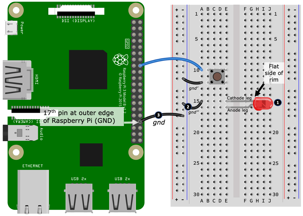
Here is how to connect the LED into your breadboard and connect it to your Raspberry Pi. The following step numbers match the numbered black circles in Figure 2.5 :
- Connect the LED into your breadboard as illustrated, taking care to ensure that the LED is installed the correct way around. Our illustration shows the cathode leg in hole E15 and the anode leg in hole E16.
- Next, using a jumper wire (labeled gnd"), connect the cathode leg of the LED into the same power rail shared by the push button. We have shown this connection with one end of the gnd" wire connected in hole A15, while the other end of the wire connected to a nearby hole on the left-hand side negative (-) power rail.
- Finally, using another jumper wire (labeled gnd), connect the negative (-) power rail to the 17th outer edge pin on your Raspberry Pi's GPIO header. This pin is a ground (GND) pin on your Raspberry Pi.
Well done! That's our LED connected. Next, we add the resistor, which will complete our circuit.
Positioning and connecting the resistor
A resistor is an electronic component used to limit (that is, resist) current flow and divide voltage and they are a very common electrical component.
Shown in Figure 2.6 are a physical resistor (left-hand side) and two schematic symbols (right-hand side). There is no practical difference between the schematic symbols pictured. They represent different documentation standards, and you will find that the author of a schematic diagram will choose and stick with one type of symbol. We'll be using the zig-zag symbol throughout this book:
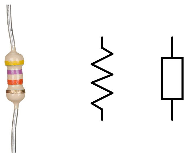
Resistors come in many shapes, sizes, and colors. As a general guide, their physical shape and size relate to their physical properties and capabilities, while the color of their casing is usually insignificant, at least as far as their properties are concerned. The colored bands on a resistor, however, are very significant as they identify the resistor's value. It's worth mentioning that small general-purpose resistors (which are what we will be using) use color bands for specifying their value, while physically larger resistors used in high power applications frequently have their resistance value printed on their casing.
Resistors are an unbiased electrical component, meaning that they can be installed in an electrical circuit either way around. Their values, however, need to be chosen correctly, otherwise a circuit may not work as intended, or worse, the resistor and/or other components (including your Raspberry Pi) can be damaged.
Our use of resistors through this book will be pragmatic. although I will be explaining how and why we arrive at the certain values we use from Chapter 6, Electronics 101 for the Software Engineer, onward. If you are new to resistors, you will find two links in the Further reading section where you can learn more about them, including how to read their values.
Figure 2.7 demonstrates the resistor connection we need to create. Please refer to this as you follow the forthcoming steps:
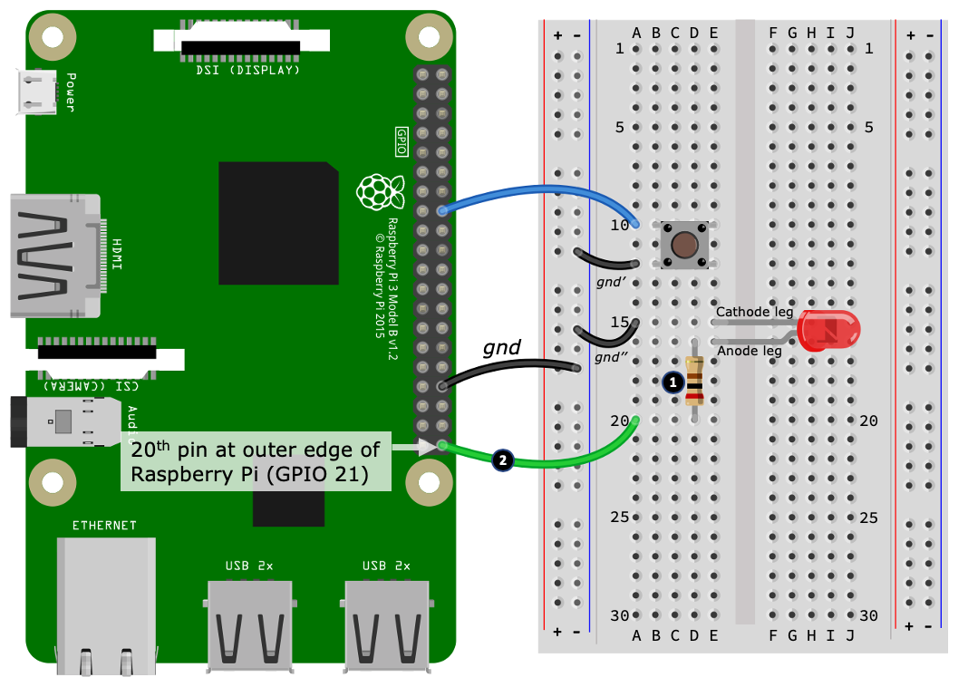
Here is how to connect the resistor into your breadboard. The following step numbers match the numbered black circles in Figure 2.7:
-
Place one leg (is does not matter which one) of the resistor into a hole that shares the same row as the LED's anode leg. This connection is shown at hole D16. Insert the other leg inserted into a vacant row, shown at D20 (it'll be a vacant row on your breadboard until we connect the wire next).
-
Using a jumper wire (illustrated starting at hole A20), we connect the other leg of our resistor to the 20th pin on the outer edge of your Raspberry Pi's GPIO header. This pin is known as GPIO 21.
Well done! With that last connection, we have created our first circuit. We'll be using this base circuit throughout the rest of this chapter and in the next two chapters, Chapter 3, Networking with RESTful APIs and Web Sockets Using Flask, and Chapter 4, Networking with MQTT, Python, and the Mosquitto MQTT Broker. We will start to explore a range of other circuits from Chapter 5, Connecting Your Raspberry Pi to the Physical World, onward.
Now that we have completed our breadboard circuit and learned how components and wires are connected on our breadboard, we are ready to explore a diagramming technique that is used to describe electrical circuits.
Reading an electronic schematic diagram
In the last section, we built our first circuit on a breadboard by following a series of illustrated steps. In this section, we will learn about schematic diagrams, which is a formal way of documenting and describing an electrical circuit. These are the diagrams you find in electronic texts and datasheets.
We will learn how to read a simple schematic diagram and how it relates back to the breadboard layout we just created. Understanding how the two relate, and especially being able to create a breadboard layout from a schematic diagram, is an important skill you will need to develop as you continue your electronics and IoT journey.
The electronic circuits and schematic diagrams we will be seeing and working with throughout this book will be relatively simple as far as schematic diagrams are concerned. We will address important concepts and component symbols as we encounter them on a case-by-case basis. For our journey, a full and detailed explanation of the ins and outs of schematic diagramming is unnecessary and beyond the practical scope of this book. However, I encourage you to read through the Spark Fun tutorial that's mentioned in the Further reading section. It provides a brief, yet comprehensive overview of reading schematic diagrams and will provide you with a good foundational understanding of this diagramming technique and its semantics.
Let's start by looking at a schematic diagram that represents the breadboard circuit we just created as shown in Figure 2.7. Our semantic diagram is illustrated here:

A schematic diagram can be correctly drawn in a multitude of ways; however, I've purposely drawn this diagram (and will do so where appropriate in this book) to closely resemble its equivalent breadboard layout to help with its interpretation and understanding.
We'll learn to read this schematic diagram by first explaining the push button connection and wiring.
Reading the push button schematic connection
I've combined the breadboard layout and schematic diagram (with a few additional labels) as follows:

Here is how to read the pushbutton connection. The following step numbers match the numbered black circles in Figure 2.9:
-
Start at the breadboard with the wire labeled wire 1. If we look at the ends of this wire, we see that one end is connected to GPIO 23 on the Raspberry Pi, while the other end (at hole A10) connects to a row shared by the push button.
-
Looking at the schematic diagram, this breadboard connection is depicted diagrammatically by the line labeled wire 1. You will notice one end of the line is labeled GPIO23, while the other end leads into one side of the button symbol.
-
Next, starting at the other side of the push button on the breadboard (hole A12), notice the wire labeled gnd'. This wire connects the push button to the outer power rail on the breadboard.
-
Five holes down from this first power rail connection, we see a second ground wire (labeled gnd) leading from the breadboard back to a GND pin on the Raspberry Pi.
-
The breadboard gnd and gnd' wire connections are seen in the schematic diagram as the line labeled gnd, which leads out of the button and ends at a downward pointing arrow symbol annotated GND (remember gnd and gnd' are electrically connected on the breadboard and are therefore logically a single wire). This is the symbol for a ground connection, and you will frequently see this symbol repeated a lot in schematic diagrams. I'll have more to say about this symbol when we reach the section titled Reading and understanding the ground symbol.
-
Examine the button symbol in the schematic diagram and you will notice that the wire 1 and gnd lines are not joined but rather terminate in the button symbol (the small circles). This is known as a normally open connection or, in our specific case, a normally open switch. You can think of normally open as meaning the line is broken (and remember a line represents a wire). Now, if you imagine the button pressed, then the button touches each circle and connects the blue and gnd lines, resulting in a closed connection that completes the circuit between GPIO 23 and GND. We'll discuss this idea more in Chapter 6, Electronics 101 for the Software Engineer.
When you are comfortable that you understand how the push button connections on the breadboard match the push button section of the schematic diagram, we will proceed and discuss LED and resistor connections.
Reading the LED and resistor schematic connection
Continuing from the previous section, where we learned how to read and understand the push button part of the schematic diagram, next we complete our explanation by covering the LED and resistor connections, as shown here:

Here is how to read the LED and resistor connection. The following step numbers match the numbered black circles in Figure 2.10:
- Start at the wire labeled wire 2 on the breadboard. This wire connects GPIO 21 on the Raspberry Pi into the row shared by one end of the resistor (hole A25).
- The wire 2 connection is depicted by the line also labeled wire 2 on the schematic diagram.
- On the breadboard, the other end of the resistor is connected to the anode leg of the LED (hole E15). Remember, the resistor and anode leg of the LED are electrically connected because they share the same row of holes in the same bank on the breadboard.
- We see the resistor/LED connection in the schematic diagram where the resistor symbol meets the LED symbol. We know the resistor connects to the anode side of the LED in the diagram by the way the LED symbol is orientated.
- Next, on the breadboard, the other leg of the LED (hole E15)—the cathode leg—connects to the gnd" wire (hole A15), which then connects back to the outer power rail that is also shared by the push button's gnd' wire (which is then connected back to the Raspberry Pi's GND pin with the gnd wire.)
- Finally, on the schematic diagram, this connection from the LED cathode leg to GND is depicted by the line labeled gnd (the same one used by the push button).
We have now completed our schematic diagram explanation. How did you do? I hope you were able to trace around the diagram and see how it relates back to the circuit we built on the breadboard.
Our last step illustrates an important concept in electronics—a common ground. We'll discuss this concept in more detail next.
Introducing ground connections and symbols
Electrical circuits all require a common electrical point of reference, and we call this point ground. This is why we see the push button and LED sharing a common connection on both the breadboard and schematic diagram (as a reminder, refer to Figure 2.10.
For the simple circuits presented throughout this book and when working with your Raspberry Pi's GPIO pins, it will be practical to consider the terms negative and ground as interchangeable. This is because the negative side of a power source will be our common point of electrical reference (and yes, GPIO pins are a source of power, which we will explore more in Chapter 6, Electronics 101 for the Software Engineer).
As mentioned previously in the Reading the push button schematic connection section, in step 4, we diagrammed the ground point using an arrow symbol. Our ground symbol (made out of line segments) is one common variation of a ground symbol. You'll see another variation in Figure 2.11:
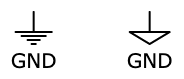
All ground points are electrically connected, and we may repeat the symbol many times in a schematic diagram to help to simplify the diagram. By using the ground symbol to indicate a common ground connection, we remove the need to draw many interconnecting lines to join all ground connections together (which would get rather messy for large or more complex circuits).
Our simple circuit certainly does not come under the banners of large or complex, however, to illustrate the concept of common ground, I have redrawn the schematic diagram shown originally in Figure 2.8 here, only this time using multiple ground symbols:

Although our alternative schematic diagram looks like two separate circuits, they are electrically connected exactly the same as our original schematic diagram in Figure 2.8.
Please take a moment now to examine both Figure 2.8 and Figure 2.12 and see whether you can work out how the two diagrams are electrically the same.
All I have done here is broken the line (labeled gnd in Figure 2.8) and redrawn the push button subcircuit and LED/resistor subcircuit in a different orientation and used separate ground symbol for each subcircuit.
As mentioned previously, at this stage of this book, we do not go into how or why this circuit works electronically or how it interacts electrically with the GPIO pins on your Raspberry Pi. We'll cover these topics and many more with practical and illustrative exercises when we reach Chapter 6, Electronics 101 for the Software Engineer.
Now that you have seen the schematic diagram that documents our breadboard circuit and see how they relate to one another, we're finally ready to dive into code and learn two ways to make our LED flash in Python!
Exploring two ways to flash an LED in Python
In this section, we will investigate two alternative GPIO libraries and ways to make an LED flash in Python, including the following:
- The GPIOZero library: An entry-level GPIO library
- The PiGPIO library: An advanced GPIO library
As we learn to use these two libraries, we will see how they approach GPIO control differently and discover their relative strengths and weaknesses.
After completing this section (and the following section, Exploring two ways to integrate a push button in Python), you will have explored and compared two very different approaches to GPIO control—the high-level (using GPIOZero) and a lower-level (using PiGPIO)—and have a good introductory grasp of when and how you would choose between the alternative when building an electronic interfacing program.
Let's start our practical exercises by making the LED blink using GPIOZero.
Blinking with GPIOZero
We are now ready to investigate our first blinking method using the GPIOZero library. You will find the code we are about to cover in the chapter02/led_gpiozero.py file. Please review this file before proceeding.
We will start by running our example code.
Run the program using the following command, remembering that you need to be in the activated virtual environment (if you need a refresher on how to activate a Python virtual environment, see Chapter 1, Setting Up Your Development Environment):
(venv) $ python led_gpiozero.py
If the LED is connected correctly, it should blink.
Now that we have run the code and seen the LED blink, it's time to look through the code that makes this happen.
Imports
We will start our code exploration by looking at the external libraries we are importing in our Python program. They appear near the top of the source file, as shown here:
from gpiozero import Device, LED                # (1)
from gpiozero.pins.pigpio import PiGPIOFactory  # (2)
from time import sleep
The imports of interest are the following:
- At line (1), we import the Device and LED classes from the GPIOZero package.
- At line (2), we are importing a GPIOZero Pin Factory. This is used together with the Device class, which we'll see next.
Next, we see how to set the GPIOZero Pin Factory implementation.
Pin Factory configuration
A Pin Factory is used in GPIOZero specify which concrete GPIO library GPIOZero will use to perform the actual GPIO work. We will discuss Pin Factories in more detail when we compare the GPIOZero and PiGPIO examples later in this chapter in the Comparing the GPIOZero and PiGPIO examples section:
Device.pin_factory = PiGPIOFactory() # (3)
On line (3), we are telling GPIOZero to use PiGPIO as its Pin Factory using the Device and PiGPIOFactory imports.
Now that we've seen how a Pin Factory is set up, let's look at the code that makes our LED blink.
Blinking the LED
Here, we see the LED class at line (4) in the following is created and assigned to the led variable. The parameter to LED is the GPIO pin that the physical LED is connected to, as per the breadboard in Figure 2.1:
GPIO_PIN = 21
led = LED(GPIO_PIN)         # (4)
led.blink(background=False) # (5)
On line (5), we start the LED blinking. The background=False parameter to blink() is needed to run the LED on the main thread so the program does not exit (an alternative of background=True would be to use signal.pause(). We'll see an example of this in the next section).
GPIOZero makes it very easy to interface with common electronic components such as an LED. Next, we will perform the same exercise, only this time using the PiGPIO library.
Blinking with PiGPIO
Now that we have seen how to blink our LED using the GPIOZero library, let's look at an alternative method using the PiGPIO library.
The code we are about to walk through is contained in the chapter02/led_pigpio.py file. Terminate the previous example if it is still running, and run led_pigpio.py. The LED should blink again.
Let's walk through the PiGPIO version of our LED blinking code.
Imports
Starting at the top of the file, we have the import section of the source file:
import pigpio           # (1)
from time import sleep
This time around, on line (1), we only need to import the PiGPIO module.
Next, we will see how to configure PiGPIO and set the I/O mode on the GPIO pin that is connected to our LED.
PiGPIO and pin configuration
Let's look at the code that configures PiGPIO and the LED's GPIO pin:
GPIO_PIN = 21
pi = pigpio.pi()                        # (2)
pi.set_mode(GPIO_PIN, pigpio.OUTPUT)    # (3)
We create an instance of PiGPIO on line (2) and assign it to the pi variable. We use this variable to interact with the PiGPIO library from this point forward in the code.
On line (3), we configure GPIO pin 21 to be an output pin. Configuring a pin as output means we want to use that pin to control something connected to it from our Python code. In this example, we want to control the LED. Later in this chapter, we'll see an example of an input pin used to respond to button presses.
Now that we have imported our required libraries and configured PiGPIO and the out GPIO pin, let's now see how we are making the LED blink.
Blinking the LED
Finally, we make our LED blink:
while True:
 pi.write(GPIO_PIN, 1) # 1 = High = On    # (4)
 sleep(1) # 1 second
 pi.write(GPIO_PIN, 0) # 0 = Low = Off    # (5)
 sleep(1) # 1 second
We achieve the blinking with PiGPIO using a while loop. As the loop executes, we are toggling GPIO pin 21— our output pin—on and off (lines (4) and (5)), with a short sleep() function in between, hence making the LED appear to blink.
Next, we will compare our two libraries and their different approaches to blinking the LED.
Comparing the GPIOZero and PiGPIO examples
If you look at the code for the GPIOZero example, it's pretty obvious we're making an LED blink—it's pretty explicit in the code. But what about the PiGPIO example? There is no mention of LEDs or blinking. In truth, it could be doing anything—it's just we know an LED is connected to GPIO 21.
Our two blinking examples reveal important aspects of GPIOZero and PiGPIO:
-
GPIOZero is a higher-level wrapper library. On the surface, it abstracts common electronic components such as LEDs into simple-to-use classes while, underneath, it is delegating the actual interfacing work to a concrete GPIO library.
-
PiGPIO is a lower-level GPIO library where you work with, control, and access GPIO pins directly.
GPIOZero performs its delegation to an external GPIO library using a Pin Factory. In our example, we delegated to PiGPIO using the line, Device.pin_factory = PiGPIOFactory(). We'll pick up the topic of GPIOZero and delegation again in Chapter 5, Connecting your Raspberry Pi to the Physical World.
As we proceed through this book, we will be using both GPIOZero and PiGPIO. We'll use GPIOZero to simplify and condense code where appropriate, while we will be using PiGPIO for more advanced code examples and to teach core GPIO concepts that are otherwise abstracted away by GPIOZero.
Next, we will continue building on our LED blinking examples by integrating the push button.
Exploring two ways to integrate a push button in Python
In the previous section, we explored two different approaches to making our LED blink—one using the GPIOZero library and the other with the PiGPIO library. In this section, we will integrate the push button from the circuit in Figure 2.1 with Python and see how we can integrate the button using both the GPIOZero and PiGPIO libraries.
We will start by making our LED turn on and off with a button that is integrated using the GPIOZero library.
Responding to a button press with GPIOZero
The code we are about to cover is included in the chapter02/button_gpiozero.py file. Please review and run this file. The LED should turn on and off as you press the button. As per the circuit in Figure 2.1, the LED is still connected to GPIO 21, while our button is connected to GPIO 23.
Let's walk through the significant parts of the code, noting that we are skipping sections of code that we've already covered.
Imports
Starting at the top of the source file, you will find the section of code where we import external libraries, as shown here:
from gpiozero import Device, LED, Button         # (1)
from gpiozero.pins.pigpio import PiGPIOFactory
import signal                                    # (2)
For this example, we have also imported the GPIOZero Button class (1) and the Python signal module (2).
Now that you have seen that we are importing the Button class, let's look at the handler function that will be called when the button is pressed.
Button pressed handler
We are using a callback handler to respond to button presses, defined in the pressed() function:
def pressed():
    led.toggle()                               # (3)
    state = 'on' if led.value == 1 else 'off'  # (4)
    print("Button pressed: LED is " + state)   # (5)
On line (3), our LED is turned on and off each time pressed() is invoked using the toggle() method of led. On line (4), we query the value property of led to determine whether the LED is on (value == 1) or off (value == 0) and store it in the state variable, which we print to the Terminal on line (5).
Let's continue and see how to create and configure a Button class instance and register the pressed() function so it is called when you press the physical button.
Button configuration
Following are the lines used to configure the push button. On line (6), the class we use is Button. In GPIOZero, we use a Button class for any input device that can be either on or off, such as buttons and switches:
button = Button(BUTTON_GPIO_PIN,
                pull_up=True, bounce_time=0.1)  # (6)
button.when_pressed = pressed                   # (7)
On line (7), we register the pressed() callback handler with our button instance.
Here are the meanings of the parameters to the Button constructor on line (6):
- The first parameter is the button's GPIO pin (BUTTON_GPIO_PIN == 23).
- The second parameter, pull_up=True, enables an internal pull-up resistor for GPIO 23. Pull-up and pull-down resistors are an important concept in digital electronics. We're are going to skip over this concept for now because we will be covering the importance and use of pull-up and pull-down resistors in greater detail in Chapter 6, Electronics 101 for the Software Engineers.
- The third parameter bounce_time=0.1 (0.1 seconds), is used to compensate for an occurrence known as switch or contact bounce.
Bounce is a type of electrical noise that occurs as the metal contacts within a physical button or switch come together. The result of this noise is seen as a rapid succession of on-off (or high-low) states changes on a digital input pin. This is undesirable because we want one physical press of a button (or toggle of a switch) to be seen as one state change on the input pin. This is commonly achieved in code using a debounce threshold or timeout, which in our case is the amount of time that our Raspberry Pi ignores successive pin stage changes following an initial state change.
Try setting bounce_time=0 (no debouncing). You should find that the button behaves very erratically. Then, use a higher number such as bounce_time=5 (5 seconds), and you will find that after the first press the button is non-responsive until the duration expires.
Finally, let's cover a common technique that is used to prevent an electronic-interfacing Python program from exiting.
Preventing the main thread from terminating
It's common to see the use of signal.pause() or an equivalent construct in GPIO examples and programs:
signal.pause() # Stops program from exiting. # (8)
Line (8) prevents the main program thread from reaching its natural end, which under normal circumstances is where the program terminates.
We didn't need signal.pause() with our previous LED flashing examples. Here is why:
- Our GPIOZero example (chapter02/led_gpiozero.py) used background=False in the LED constructor. This prevented our program from exiting by keeping the LED's thread in the foreground.
- In the PiGPIO example (chapter02/led_pigpio.py), it's the while loop that prevents the program from exiting.
If this seems confusing, don't worry! Knowing how to prevent a program from existing abnormally all comes down to experience, practice, and understanding how Python and GPIO libraries work.
Next, let's see how to integrate the button using PiGPIO.
Responding to a button press with PiGPIO
We will now replicate the same functionality as our previous GPIOZero example to turn our LED on and off with a button press, only this time using the PiGPIO library. The code for our PiGPIO example can be found in the chapter02/button_pigpio.py file. Please review and run this file now, and confirm that the LED responds to your button presses.
Let's unravel the interesting parts of the code, starting with the GPIO pin configuration for the push button (again, noting that we're skipping sections of code that we've already covered).
Button pin configuration
Starting on line (1), we configure GPIO pin 23 (BUTTON_GPIO_PIN == 23) as an input pin:
pi.set_mode(BUTTON_GPIO_PIN, pigpio.INPUT)           # (1)
pi.set_pull_up_down(BUTTON_GPIO_PIN, pigpio.PUD_UP)  # (2)
pi.set_glitch_filter(BUTTON_GPIO_PIN, 10000)         # (3)
Next, on line (2), we enable an internal pull-up resistor for pin 23. In PiGPIO, we debounce the push button on line (3) using the pi.set_glitch_filter() method. This method takes the parameter in milliseconds.
Notice, in PiGPIO, we needed to configure each property for our button (pin input mode, a pull-up resistor, and debouncing) as a discrete method call, whereas in the previous GPIOZero example this all occurred on a single line when we created an instance of the GPIOZero LED class.
Button pressed handler
Our button callback handler is defined at starting on line (4) and is more involved than the previous GPIOZero handler:
def pressed(gpio_pin, level, tick):                         # (4)
    # Get current pin state for LED.
    led_state = pi.read(LED_GPIO_PIN)                       # (5)

    if led_state == 1:                                      # (6)
        # LED is on, so turn it off.
        pi.write(LED_GPIO_PIN, 0) # 0 = Pin Low = Led Off
        print("Button pressed: Led is off")
    else: # 0
        # LED is off, so turn it on.
        pi.write(LED_GPIO_PIN, 1) # 1 = Pin High = Led On
        print("Button pressed: Led is on")

# Register button handler.
pi.callback(BUTTON_GPIO_PIN, pigpio.FALLING_EDGE, pressed)  # (7)
Notice the signature of pressed(gpio_pin, level, tick). Our previous GPIOZero version has no parameters while PiGPIO has three mandatory parameters. Our simple one-button example does not use these parameters; however, for completeness they are as follows:
- gpio_pin: This is the pin responsible for invoking the callback. This will be 23 in our example.
- level: This the state of the pin. For us, this will be pigpio.FALLING_EDGE (we'll see why shortly).
- tick: This is the number of microseconds since boot.
On line (5), we read the current state of GPIO 21 (our LED) into a variable with led_state = pi.read(). Then, starting on line (6), depending on whether the LED is currently on (led_state == 1) or off (led_state == 0), we set the GPIO 21 high or low using pi.write() to toggle the LED to its inverse on or off state.
Finally, the callback handler is registered on line (7). The parameter value, pigpio.FALLING_EDGE, means the call handler is pressed() whenever the GPIO pin, BUTTON_GPIO_PIN, (that is, 23) starts to transition from a digital high to a digital low. This is a lot more explicit than simply testing whether a pin is high or low; however, for simplicity, consider the following level parameter options to pi.callback(). Try changing the parameter and see what happens when you press the button:
- pigpio.FALLING_EDGE: This is low (think falling toward low). pressed() is called when you press the button.
- pigpio.RAISING_EDGE: This is high (think raising toward high). pressed() is called when you release the button.
- pigpio.EITHER_EDGE: This can be high or low. pressed() is called when you both press and release the button, effectively meaning the LED will only illuminate when you hold down the button.
Did you notice or think at any stage in the PiGPIO example that when the button is pressed—that is, you activated the button—GPIO pin 23 becomes low (that is, the pigpio.FALLING_EDGE parameter on line (7)), and this results in pressed() begin called? Did this seem a bit back-to-front or false from a programming perspective? We'll revisit this idea and discuss the reasons behind it in Chapter 6, Electronics 101 for the Software Engineer.
That's enough on GPIO libraries and electronics for now. We've seen how to respond to button presses with both the GPIOZero and PiGPIO libraries. In particular, we saw that the GPIOZero approach was rather simple and straightforward compared to the PiGPIO approach, which involved more code and more configuration. This is the same outcome we discovered in the previous section, Exploring two ways to flash an LED in Python—that is, the GPIOZero approach was simpler.
Is one approach better than the other? The answer to that all depends on what goal you are trying to achieve and how much lower-level control you require over your electronic interfacing to achieve that goal. At this stage of this book, I just wanted to give you contrasting options regarding GPIO libraries and how we interface them with electronics. We'll be picking this topic up again in greater detail when we revisit popular GPIO libraries for Python in Chapter 5, Connecting Your Raspberry Pi to the Physical World.
Let's move on and create an IoT program to control our LED over the internet.
Creating your first IoT program
We are about to create a Python program to integrate with a service called dweet.io. This is how their website describes the service: "it's like Twitter for social machines."
We will create simple dweets, which are the dweet.io equivalent of a tweet, by pasting a URL into a web browser.
Our program will monitor and receive our dweets by polling a dweet.io RESTful API endpoint for data. As data is received, it will be parsed to find an instruction specifying whether our LED should be turned on or off or made to blink. Based on this instruction, our LED state will be changed using the GPIOZero library. We'll have a look at data format received from dweet.io when we discuss the program's code in a subsequent section titled Understanding the server code.
The code for this program is contained in the chapter02/dweet_led.py file. Read through the source code in this file to get a broad perspective about what's happening before continuing.
Running and testing the Python server
In this section, we will run and interact with a Python server program that will let us control our LED from a web browser by copying and pasting links. Once we have used the program to control our LED, we'll then delve into the mechanics of the code and how it works in the next section.
Here are the steps to follow:
- Run the chapter02/dweet_led.py program. You should see output similar to the following:
(venv) $ python dweet_led.py
INFO:main:Created new thing name a8e38712                  # (1)
LED Control URLs - Try them in your web browser:
 On    : https://dweet.io/dweet/for/a8e38712?state=on      # (2)
 Off   : https://dweet.io/dweet/for/a8e38712?state=off
 Blink : https://dweet.io/dweet/for/a8e38712?state=blink

INFO:main:LED off
Waiting for dweets. Press Control+C to exit.
On line (1), the program has created a unique name for our thing to use with dweet.io. You'll notice this name in the URLs starting on line (2). The name created for your thing will be different from the preceding example.
- Copy and paste the URLs at starting on line (2) into a web browser (it could be a computer other than your Raspberry Pi). After a short delay, the LED should change its state (on, off, or blinking) depending on the URL used.
Once you have confirmed that the LED is controllable using the URLs, we will proceed and look at the program.
Understanding the server code
In this section, we will step through the major parts of the dweet_led.py program and discover how it works, starting with the imports.
Imports
First, at the start of the source code file, we see the Python imports:
...truncated...
import requests     # (1)
There is one specific import I want to draw your attention to. On line (1), we are importing the request module (this was installed earlier in this chapter when you ran pip install -r requirements.txt). requests is a high-level library for making HTTP requests in Python. Our program uses this module to communicate with the dweet.io APIs, which we'll see shortly.
Now that we understand that we are importing and will later use the requests library, let's cover the global variables used in our program.
Variable definitions
Next, we define several global variables. For now, review the following comments for their purposes. You'll see them being used as we progress through the code:
LED_GPIO_PIN = 21                  # LED GPIO Pin
THING_NAME_FILE = 'thing_name.txt' # Thing name file
URL = 'https://dweet.io'           # Dweet.io service API
last_led_state = None              # "on", "off", "blinking"
thing_name = None                  # Thing name
led = None                         # GPIOZero LED instance
As you read through the master source file, following these variable definitions, you'll also notice that we are using the Python logging system instead of print() statements:
logging.basicConfig(level=logging.WARNING)
logger = logging.getLogger('main') # Logger for this module
logger.setLevel(logging.INFO) # Debugging for this file.   # (2)
If you need to turn on debugging for the program to diagnose a problem or to see the raw JSON data exchanged between our program and the dweet.io service, change line (2) to logger.setLevel(logging.DEBUG).
Next, we will step through the significant methods in the program and see what they do.
The resolve_thing_name() method
The resolve_thing_name() method is responsible for loading or creating a unique name for our thing for use with dweet.io.
Our intention when using this method is to always reuse a name so that our dweet URLs for controlling our LED remain the same between the program restarts:
def resolve_thing_name(thing_file):
    """Get existing, or create a new thing name"""
    if os.path.exists(thing_file):                     # (3)
        with open(thing_file, 'r') as file_handle:
            name = file_handle.read()
            logger.info('Thing name ' + name +
                        ' loaded from ' + thing_file)
            return name.strip()
    else:
        name = str(uuid1())[:8]                        # (4)
        logger.info('Created new thing name ' + name)

        with open(thing_file, 'w') as f:               # (5)
            f.write(name)

    return name
On line (3), we load a name stored previously in thing_file if the file exists; otherwise, we use the Python UUID module method uuid1() on line (4) to create an 8-character unique identifier and use that as the thing name. We store this newly created identifier-cum-name in thing_file on line (5).
Next, we will look at the function that retrieves the last dweet made to our thing.
The get_lastest_dweet() method
get_lastest_dweet() queries the dweet.io service to retrieve the latest dweet (if any) made for our thing. Following is an example of the JSON response we expect to receive. It is the content.state property on line (1) that we are ultimately interested in:
{
  this: "succeeded",
  by: "getting",
  the: "dweets",
  with: [
    {
      thing: "a8e38712-9886-11e9-a545-68a3c4974cd4",
      created: "2019-09-16T05:16:59.676Z",
      content: {
        state: "on"                                       # (1)
      }
    }
  ]
}
Looking at the following code, we see, on line (6), the creation of the resource URL used to query the dweet.io service. A call to this URL will return us a JSON similar to that shown in the preceding. You will find a link in the Further reading section to the complete dweet.io API reference.
Next, on line (7), the requests module use used to make an HTTP GET request to retrieve the latest dweet:
def get_lastest_dweet():
    """Get the last dweet made by our thing."""
    resource = URL + '/get/latest/dweet/for/' + thing_name   # (6)
    logger.debug('Getting last dweet from url %s', resource)

    r = requests.get(resource)                               # (7)
Starting on line (8) in the following, we check whether the request succeeded at the HTTP protocol level. If successful on line (9), we then proceed to parse the JSON response and extract and return the content property starting on line (10):
    if r.status_code == 200:                              # (8)
        dweet = r.json() # return a Python dict.
        logger.debug('Last dweet for thing was %s', dweet)

        dweet_content = None

        if dweet['this'] == 'succeeded':                  # (9)
            # Interested in the dweet content property.
            dweet_content = dweet['with'][0]['content']   # (10)

        return dweet_content
    else:
        logger.error('Getting last dweet failed
                     with http status %s', r.status_code)
        return {}
Our next method to cover is poll_dweets_forever(), which will use get_lastest_dweet().
The poll_dweets_forever() method
poll_dweets_forever() is a long-running function that periodically calls on line (11) the get_lastest_dweet() method we just covered. When a dweet is available, it is handled on line (12) by process_dweet(), which we will discuss shortly:
def poll_dweets_forever(delay_secs=2):
    """Poll dweet.io for dweets about our thing."""
    while True:
        dweet = get_last_dweet()                        # (11)
        if dweet is not None:
            process_dweet(dweet)                        # (12)

    sleep(delay_secs)                                   # (13)
We sleep for a default delay of 2 seconds on line (13) before continuing the loop. Practically, this means there will be up to an approximate 2-second delay between using one of the dweeting URLs to request a LED state change and the LED altering its state.
The polling-based approach of poll_dweets_forever() was chosen here for discussion for simplicity. It will become clear as you read on where you can switch approaches.
Our next stop is the method we use to control the LED.
The process_dweet() method
As we saw previously when poll_dweets_forever() (similar to stream_dweets_forever()) gets a dweet, it parses out the content property from the dweet's JSON. This is then passed to process_dweet() for handling, where we extract the state child property from the content property:
def process_dweet(dweet):
    """Inspect the dweet and set LED state accordingly"""
    global last_led_state

    if not 'state' in dweet:
        return

    led_state = dweet['state']                         # (14)

    if led_state == last_led_state:                    # (15)
        return; # LED is already in requested state.
On line (15) (and (17) in the subsequent code block), we test for and maintain the LED's last known state and avoid interacting with the LED if it's already in the requested state. This will avoid potential visual glitching of the LED that can occur if it's repeatedly put into a blinking state when already blinking.
The core of process_dweet() is to access the state property of the dweet and change the LED's state, which starts on line (16):
    if led_state == 'on':                 # (16)
        led_state = 'on'
        led.on()
    elif led_state == 'blink':
        led_state = 'blink'
        led.blink()
    else: # Off, including any unhanded state.
        led_state = 'off'
        led.off()

     last_led_state = led_state           # (17)
     logger.info('LED ' + led_state)
Following line (16), we set the LED state based on the dweet (remember the led variable is a GPIOZero LED instance) before keeping track of the new state on line (17), as mentioned, for subsequent testing when process_dweet() is called on line (15).
Thanks to the simplicity of GPIOZero, our LED controlling code only makes a fleeting appearance in the code!
We will conclude by covering the program's main entry point.
The main program entry point
At the end of the source file, we have the following code:
# Main entry point
if __name__ == '__main__':
    signal.signal(signal.SIGINT, signal_handler) # Capture CTRL + C
    print_instructions()                              # (18)

    # Initialize LED from last dweet.
    latest_dweet = get_latest_dweet()                 # (19)
    if (latest_dweet):
        process_dweet(latest_dweet)

    print('Waiting for dweets. Press Control+C to exit.')

    #Only use one of the following.
    #stream_dweets_forever() # Stream dweets real-time.
    poll_dweets_forever() # Get dweets by polling.    # (20)
On line (8), print_instructions() is responsible for printing the sweet URLs to the Terminal, while on line (19), we see a call to get_latest_dweet(). This call initializes our LED to the last dweeted state when the program starts. Finally, on line (20), we start polling the dweet.io service to access the latest dweets. It's here you swap the dweet polling method to the streaming method.
This now completes our walk-through of dweet_led.py. Through this discussion, we have now seen how to leverage the dweet.io service to create a simple and functional IoT program. Before we complete this chapter, I want to leave you with two bonus source code files that you can use to extend your IoT program.
Extending your IoT program
The following two files in the chapter02 folder complement what we have covered in this chapter by combining the concepts we have learned. As the overall code and approach are similar to what we have already covered, we will not go through the code in detail:
- dweet_button.py provides an implementation showing how to use a push button to create a dweet with the dweet.io service. This will let you change your LED state with the press of a button.
- pigpio_led_class.py provides a code-level example of how a low-level library like PiGPIO relates to a high-level library like GPIOZero.
We'll start by discussing dweet_button.py.
Implementing a dweeting button
This program in dweet_button.py integrates the GPIOZero push button example with dweet.io. Earlier in this chapter, in the section titled Running and testing the Python server, we copied and pasted URLs into a web browser to control our LED.
When you run dweet_button.py, each time you press the button, this program cycles through the dweet.io URLs to change the LED's state. To configure this program, find and update the following line with the thing name you are using with dweet_led.py:
thing_name = '**** ADD YOUR THING NAME HERE ****'
Remember, that you'll also need the dweet_led.py program to be running in a Terminal, otherwise, the LED will not respond to your button presses.
Next, we see how to mimic GPIOZero using PiGPIO and a Python class.
PiGPIO LED as a class
In the pigpio_led_class.py file, we have a Python class that is a re-engineering of the PiGPIO LED example to wrap it as a class that mimics the GPIOZero LED class. It demonstrates the basic principle of how GPIOZero abstracts away lower-level GPIO complexity. This re-engineered class can be used as a drop-in replacement for the GPIOZero LED examples in this chapter, as shown here. See the header comments in pigpio_led_class.py for more information:
""" chapter02/dweet_led.py """
...
# from gpiozero import LED                    # Comment out import
from pigpio_led_class import PiGPIOLED as LED # Add new import
I hope you find these two bonus files interesting, and that by exploring the PiGPIO LED as a class example, you can better appreciate how the higher-level GPIOZero library and lower-level PiGPIO library relate to one another.
At this stage of your journey, if you are a little unclear about what's happening with pigpio_led_class.py, do not get worried. I wanted to simply set out a brief example of GPIO library interactions for you to ponder in the context of an end-to-end application, as this will serve as a point of reference as you continue reading. We'll be covering the GPIOPZero and PiGPIO libraries (plus others) in greater detail in Chapter 5, Connecting Your Raspberry Pi to the Physical World, plus we'll be covering more advanced concepts such as threading in electronic interfacing programs (similar to the use of threads in pigpio_led_class.py) in Chapter 12, Advanced IoT Programming Concepts – Threads, AsyncIO, and Event Loops.
Summary
Through this chapter, you've just created a real functional IoT application using a Raspberry Pi and Python. We saw two alternative ways to flash a LED and read a button press in Python using both the GPIOZero and PiGPIO GPIO libraries. We also compared the use of these libraries and saw that GPIOZero takes a higher-level and more abstract approach to coding and GPIO control than does the lower-level PiGPIO library. We also connected the LED to the internet using the online dweet.io service. Using simple URLs, we were able to turn on and off and blink the LED by simply visiting the URLs in a web browser.
As you proceed through the subsequent chapters in this book, we'll be building on and going deeper into the core knowledge you have learned in this chapter about GPIO interfacing, electronic circuits, and controlling a circuit over the internet. We will learn alternative approaches to building an application to those we have covered in this chapter and discover the core principles related to GPIO control and electronic interfacing. Equipped with this deepening knowledge, you'll be able to create even more powerful and grand IoT solutions by the time you complete this book!
In Chapter 3, Networking with RESTful APIs and Web Sockets Using Flask, we will be looking at the popular Flask microservices framework, and we will create two Python-based web servers and accompanying web pages to control the LED over a local network or the internet.
Questions
Here is a list of questions for you to test your knowledge regarding this chapter's material. You will find the answers in the Assessments section of the book:
- You don't have the correct resistor value. Can you just substitute another value resistor that you have lying around?
- The GPIOZero package is a compete GPIO library. Is it all you'll ever need?
- Should you always use the built-in Python packages for networking wherever possible?
- True or false: an LED is unbiased, meaning it can be plugged into a circuit any way around and still work.
- You are building an IoT application that interacts with other existing networked devices and it times out. What could be the problem?
- What Python module and function can be used to stop a program exiting?
Further reading
We connected our LED to the internet using the dweet.io service and called its RESTful APIs, which are documented at the following:
- Dweet.io API documentation: https://dweet.io
You may wish to familiarize yourself with the GPIOZero library briefly to get an idea about what it can do. It's well documented with heaps of examples. Here are a couple of useful links to relevant parts of the API documentation that we've covered so far:
- GPIOZero home page: https://gpiozero.readthedocs.io
- Output Devices (LED): https://gpiozero.readthedocs.io/en/stable/api_output.html
- Input Devices (Button): https://gpiozero.readthedocs.io/en/stable/api_input.html
Regarding PiGPIO, here are the relevant parts of its API documentation. You'll notice that PiGPIO is a more advanced GPIO library with less verbose documentation.
- The PiGPIO Python home page: http://abyz.me.uk/rpi/pigpio/python.html
- The read() method: http://abyz.me.uk/rpi/pigpio/python.html#read
- The write() method: http://abyz.me.uk/rpi/pigpio/python.html#write
- The callback() method: http://abyz.me.uk/rpi/pigpio/python.html#callback
- set_glitch_filter(): https://abyz.me.uk/rpi/pigpio/python.html#set_glitch_filter
Resistors are a very common electronic component. The following resources provide an overview of resistors and how to read their color bands to determine their resistance value in Ohms:
- Resistor overview: https://www.electronics-tutorials.ws/resistor/res_1.html
- Reading color bands: https://www.electronics-tutorials.ws/resistor/res_2.html
The following Spark Fun tutorial provides an excellent introduction to reading schematic diagrams:
- How to Read a Schematic Diagram: https://learn.sparkfun.com/tutorials/how-to-read-a-schematic/all