
In this chapter, we will explore hardware and software concepts related to connecting your Raspberry Pi to the physical world. We will be covering popular numbering schemes that are used by GPIO libraries to refer to the GPIO header pins on your Raspberry Pi and provide an overview of popular GPIO libraries, in addition to the GPIOZero and PiGPIO libraries that we used in earlier chapters. As we will learn, understanding GPIO numbering schemes is crucial to ensure your understanding of how GPIO libraries work with GPIO pins.
Our journey will also include a conceptual overview and discussion of the many different ways in which electronics can be interfaced with our Raspberry Pi before we will finish with a detailed exercise and practical demonstration of two important electronic concepts—Pulse-Width Modulation (PWM) and analog-to-digital conversion.
We will cover the following topics in this chapter:
- Understanding Raspberry Pi pin numbering
- Exploring popular Python GPIO libraries
- Exploring Raspberry Pi electronic interfacing options
- Interfacing with an analog-to-digital converter
Technical requirements
To perform the exercises in this chapter, you will need the following:
- Raspberry Pi 4 Model B
- Raspbian OS Buster (with desktop and recommended software)
- A minimum of Python version 3.5
These requirements are what the code examples in this book are based on. It's reasonable to expect that the code examples should work without modification on a Raspberry Pi 3 Model B or a different version of Raspbian OS as long as your Python version is 3.5 or higher.
You will find this chapter's source code in the chapter05 folder in the GitHub repository available at the following URL: https://github.com/PacktPublishing/Practical-Python-Programming-for-IoT
You will need to execute the following commands in a Terminal to set up a virtual environment and install Python libraries required for the code in this chapter:
$ cd chapter05              # Change into this chapter's folder
$ python3 -m venv venv      # Create Python Virtual Environment
$ source venv/bin/activate  # Activate Python Virtual Environment
(venv) $ pip install pip --upgrade        # Upgrade pip
(venv) $ pip install -r requirements.txt  # Install dependent packages
The following dependencies are installed from requirements.txt:
- GPIOZero: The GPIOZero GPIO library (https://pypi.org/project/gpiozero)
- PiGPIO: The PiGPIO GPIO library (https://pypi.org/project/pigpio)
- RPi.GPIO: The RPi.GPIO library (https://sourceforge.net/p/raspberry-gpio-python/wiki/Home)
- ADS1X15: The ADS11x5 ADC library (https://pypi.org/project/adafruit-circuitpython-ads1x15)
Besides the preceding installations, we require a few physical electronic components for the exercise in this chapter:
- 1 x 5 mm red LED
- 1 x 200 Ω resistor—its color bands will be red, black, brown, and then gold or silver
- 1 x ADS1115 ADC break-out module (for example, https://www.adafruit.com/product/1085)
- 2 x 10 kΩ potentiometers (any value in the range 10K to 100K will be suitable)
- A breadboard
- Male-to-female and male-to-male jumper cables (also called DuPont cables)
Understanding Raspberry Pi pin numbering
You will have noticed by now that your Raspberry Pi has a lot of pins sticking out of it! Since Chapter 2, Getting Started with Python and IoT, and all subsequent chapters, we have referenced these pins by referring to them, for example, as GPIO Pin 23, but what does this mean? It's time we understand this in more detail.
There are three common ways in which a Raspberry Pi's GPIO pins may be referenced, as illustrated in Figure 5.1:

In all of the previous chapters, we've been talking about GPIO pins from the perspective of PiGPIO, which uses the Broadcom or BCM numbering scheme. BCM is the most common scheme used in Python-based GPIO libraries, and the GPIO libraries that we will discuss shortly all use BCM exclusively or by default. However, it is useful to know that other schemes exist because it will help when reading or debugging code fragments you come across on the internet and other resources.
Let's explore these alternatives as shown in Figure 5.1:
- Broadcom/BCM Numbering: This refers to the GPIO numbering of the Broadcom chip in your Raspberry Pi. With BCM numbering, when we say GPIO 23, we mean GPIO 23 as labeled in a BCM pin-out diagram. This is the scheme we are using with the GPIOZero and PiGPIO examples presented in this book.
- Physical/Board/P1 Header: In this numbering scheme, the physical pin numbers of the P1 header are used, for instance, BCM GPIO 23 = Physical Pin 16.
- WiringPi: This is a popular C GPIO library called WiringPi that introduced its own pin mapping scheme. Due to the maturity of WiringPi (there is a Python port), you will come across this scheme from time to time—continuing our example, BCM GPIO 23 = Physical Pin 16 = WiringPi Pin 4.
There are also other methods and naming used to reference pins and interfaces to be aware of, and they include the following:
- Virtual Filesystem: There is a virtual filesystem mounted at /sys for general GPIO access,/dev/*i2c for I2C, /dev/*spi* for SPI, and /sys/bus/w1/devices/* for 1-wire devices.
- Alternative Pin Functions: The preceding BCM diagram in Figure 5.1 lists GPIO pin numbers, together with alternative pin functions such as PWM0, I2C0, and SPI0 in parentheses. These represent alternative roles a pin can perform beyond basic digital I/O.
- Bus/Channel Numbers: For SPI and I2C interfacing and hardware PWM, it's common for a library to use the bus or channel number. For example, we can use BCM GPIO 18 as a general-purpose digital input and output, or we can use it in its alternate function mode as a hardware PWM output as PWM channel 0.
You now have an understanding of the different schemes that can be used to refer to GPIO pins on a Raspberry Pi. While the BCM scheme tends to be the most common and universal amongst Python-based GPIO libraries, it is imperative to never just assume that a GPIO library, code example, and even a breadboard layout or schematic diagram you are working with uses the BCM scheme to reference GPIO pins. A mismatch between the scheme used in code and the scheme used to physically wire electronics to the Raspberry Pi's GPIO pins is a common mistake that causes a circuit not to work.
Now that we understand the use and importance of different GPIO numbering schemes, let's move on and review popular Python GPIO libraries.
Exploring popular Python GPIO libraries
If you are anything like me, when you first start with a Raspberry Pi, you probably just want to control things. Today, for many developers, their first point of contact with physical computing using a Raspberry Pi will be via the official Raspberry Pi website and with the GPIOZero library. However, after you've been tinkering with simple electronics such as buttons, LEDs, and motors for a while, you'll want to undertake more complex interfacing. If you've taken this step—or are about to—you may find yourself in the somewhat confusing world of GPIO libraries and options. This section is here to help you to navigate this path by presenting the more popular options.
We'll start our GPIO Library overview with GPIOZero.
Reviewing GPIOZero – simple interfacing for beginners
The focus of the GPIOZero library is on simplicity, making it a no-fuss library for beginners getting into physical computing and interfacing electronics. It achieves ease-of-use by abstracting away the underlying technical complexity and allows you to write code that deals with devices and peripherals such as LEDs, buttons, and common sensors, rather than writing lower-level code that directly manages pins.
Technically, GPIOZero is not actually a full-fledged GPIO library in terms of how it interacts with GPIO pin hardware. It is a simplifying wrapper around other GPIO libraries that are employed to do the actual GPIO grunt work. In Chapter 2, Getting Started with Python and IoT, we saw a push button and LED example in both GPIOZero and PiGPIO that illustrated this point.
Here are the key highlights of GPIOZero in a nutshell:
- Description: High-level GPIO Library designed for beginners
- Pros: Easy to learn and use with excellent documentation and many examples
- Cons: Limited in scope for use beyond simple electronic interfacing
- Website: https://gpiozero.readthedocs.io
Next, we will review RPi.GPIO, a popular low-level GPIO library.
Reviewing RPi.GPIO – a low-level GPIO for beginners
We mentioned previously that the essence of GPIOZero is writing code that deals with devices and components. Well, RPi.GPIO takes a different and more classical approach where we write code that works with and manages GPIO pins directly. RPi.GPIO is a popular low-level introduction to Raspberry Pi and electronics, so you will find many examples using it across the internet.
The GPIOZero documentation has a great section on RPi.GPIO, where it explains equivalent code examples in both GPIOZero and RPi.GPIO. This is a great resource to start learning lower-level pin level programming concepts.
Here are the key highlights of RPI.GPIO in a nutshell:
- Description: Lightweight low-level GPIO
- Pros: Mature library with many code examples to be found on the internet
- Cons: Lightweight means that it is not a performance-orientated library and there's no hardware-assisted PWM
- Website: https://pypi.python.org/pypi/RPi.GPIO
Next, we will look at another high-level library designed for controlling complex devices.
Reviewing Circuit Python and Blinka – interfacing for complex devices
Blinka is a Python compatibility layer for Circuit Python (circuitpython.org), a version of Python designed for microcontrollers. It's created and championed by the electronics company Adafruit, which distributes many electronic breakout boards and gadgets. Adafruit provides quality high-level Circuit Python drivers for many of its product lines, essentially carrying forward the GPIOZero ease-of-use idea to more complex devices.
We are going to use Blinka and the Circuit Python driver library for an ADS1115 ADC breakout module later in this chapter to add analog-to-digital capabilities to our Raspberry Pi.
Here are the key highlights of Blinka in a nutshell:
- Summary: High-level library for controlling complex devices
- Pros: Makes using supported devices extremely easy irrespective of your level of experience
- Cons: For basic IO, it uses RPi.GPIO, so it has the same basic limitations
- Website: https://pypi.org/project/Adafruit-Blinka
Next, we will cover Pi.GPIO, a powerful low-level GPIO library.
Reviewing PiGPIO – a low-level GPIO library
PiGPIO is considered one of the most complete GPIO library options for the Raspberry Pi in terms of features and performance. Its core is implemented in C, and there is an official port available for Python.
Architecturally, PiGPIO is comprised of two parts:
- The pigpiod daemon service provides socket and pipe access to the underlying PiGPIO C library.
- The PiGPIO client libraries interact with the pigpiod service using sockets or pipes. It's this design that makes Remote GPIO features over a network possible with PiGPIO.
Here are the key highlights of PiGPIO in a nutshell:
- Description: An advanced low-level GPIO library
- Pros: Number of features available
- Cons: Additional setup necessary; simple documentation assumes knowledge of the underlying concepts
- Website (Python Port): http://abyz.me.uk/rpi/pigpio/python.html
Before we move on to our next library, I want to draw your attention to a feature that is unique to this library and is very useful—remote GPIO.
Exploring remote GPIO with PiGPIO (and GPIOZero)
Once you have started the pigpiod service on a Raspberry Pi (covered in Chapter 1, Setting Up Your Development Environment), there are two ways to make your code remote, and by remote, I mean that your program code can be running on any computer (not just a Raspberry Pi) and control a remote Raspberry Pi's GPIOs.
Method 1: This method involves passing the remote Raspberry Pi's IP or host address to the PiGPIO constructor. Using this approach, you can also interface with multiple Raspberry Pi GPIOs by just creating additional instances of pigpio.pi(). For instance, in the following example, any methods called on the pi instance will be executed on the 192.168.0.4 host that has the pigpiod service running:
# Python Code.
pi = pigpio.pi('192.168.0.4', 8888) # Remote host and port (8888 is default if omitted)
Method 2: A second method involves setting an environment variable on the computer and running your Python code (your Python code just needs to use the default PiGPIO constructor, pi = pigpio.pi()):
# In Terminal
(venv) $ PIGPIO_ADDR="192.168.0.4" PIGPIO_PORT=8888 python my_script.py
Remote GPIO can be a great development aid, but will add latency into your code's interaction with GPIO pins as data is transmitted over the network. This means it may not be desirable for non-development releases. Button presses, as an example, can feel less responsive, and for use cases where fast timing is important, remote GPIO may be impractical.
Finally, because it's a unique feature of the PiGPIO library, all of your code must use this library if we want remote GPIO features. If you install third-party Python libraries to drive an electronic device and it uses (for example) RPi.GPIO, this device is not remote GPO-enabled.
Next, we will look at two common lower-level libraries for I2C and SPI communication.
Reviewing SPIDev and SMBus – dedicated SPI and I2C libraries
When working with I2C and SPI-enabled devices, you will encounter the SPIDev and SMBus libraries (or comparable alternatives). SPIDev is a popular lower-level Python library for use with SPI communications, while SMBus2 is a popular lower-level Python library for use with I2C and SMBus communication. These two libraries are not general-purpose libraries—they cannot be used for basic digital I/O pin control.
When starting out, it is unlikely that you will want or need to use I2C or SPI libraries such as these directly. Instead, you will use higher-level Python libraries to work with an SPI- or I2C-enabled device that, underneath, would be using lower-level libraries like these to communicate with the physical device.
Here are the key highlights of SPIDev and SMBus2 in a nutshell:
- Description: These are lower-level libraries for SPI and I2C interfacing.
- Pros: Using a lower-level library gives you full control over an SPI or I2C device. Many high-level convenience wrappers only expose the most commonly needed features.
- Cons: Leveraging these lower-level libraries requires you to interpret and understand how to interface with electronics using low-level data protocols and bit manipulation techniques.
- SPIDev website: https://pypi.org/project/spidev
- SMBus2 website: https://pypi.org/project/smbus2
To complete this section on GPIO libraries, let me briefly discuss why this book is primarily based around the PiGPIO library.
Why PiGPIO?
You may have wondered why, of all of the options, I chose to use PiGPIO predominantly in this book. As a reader of this book, I'm assuming you have a good grounding in programming and technical concepts, and that working with and learning a library such as PiGPIO is not beyond your capabilities. PiGPIO is a comprehensive library if you are intending to extend your learning beyond the basics offered by libraries such as GPIOZero and RPi.GPIO and build more complex IoT projects in Python.
You will find the PiGPIO API and documentation is broken down into beginner, intermediate, and advanced sections, so in practice and while learning, you can mix and match how you use the library API depending on your experience level and needs.
We have now completed our exploration of several popular GPIO libraries and reviewed their basic architecture and design. Next, we will turn our attention to alternative methods through which we can connect and control electronics with our Raspberry Pi.
Exploring Raspberry Pi electronic interfacing options
We've just covered the software side of GPIO, so now we will turn our attention to the electronics side. The Raspberry Pi provides many standard ways to interface both simple and complex electronics. Often, your choice of electronic components and modules will dictate which interfacing technique you need to use, while sometimes you may get a choice.
Irrespective of whether you have a choice, your knowledge of the different options will help you to understand the how and why behind a circuit and its accompanying code and help you to diagnose and resolve any issues you may encounter.
In the following section, we will explore the concepts, followed by a practical exercise. We'll start with digital IO.
Understanding digital IO
Each of the Raspberry Pi GPIO pins can perform digital input and output. Digital simply means something is either fully on or fully off—there is no middle ground. We've been working with simple digital IO in previous chapters:
- Our LED was either on or off.
- Our button was either pressed (on) or non-pressed (off).
You will come across several interchangeable terms used to describe digital states, including the following:
- On = High = True = 1
- Off = Low = False = 0
Digital IO is a form of basic IO. Analog IO is another, so we will explore it next.
Understanding analog IO
Whereas digital deals with fully on and off states, analog deals with degrees—on, off, or somewhere in-between. Think of a window in your house. In a digital world, it could be fully open (digital high) or fully closed (digital low); however, in reality, it's analog in that we can open it somewhere between fully closed and fully open, for example, a quarter open.
Simple and common examples of analog electronic components include the following:
- Potentiometers (also known as pots): This is a dial or slider that produces a range of resistance values. Real-world examples include volume controls and header thermostat controls.
- Light-Dependent-Resistors (LDRs): These are electronic components to measure light levels, and you find these in automatic night lights.
- Thermistors: These are electronic components for measuring temperature that you might find in heaters, fridges, or anywhere where temperature is measured.
The Raspberry Pi does not come with analog IO capabilities, so we need to use external electronics known as an Analog-to-Digital-Converter (ADC) to read analog input, and this will be a core focus of a practical example later in this chapter in the section entitled Interfacing with an analog-to-digital converter.
To output an analog signal, we have two options—either use a Digital-to-Analog Converter (DAC) or use a digital technique known as PWM to produce an analog-style signal from a digital output. We will not be covering DACs in this book; however, we will be exploring PWM in depth, which we will do next.
Understanding Pulse-Width Modulation
Pulse-Width Modulation or PWM is a technique to produce an average voltage on a pin somewhere between fully on (high) and fully off (low) by rapidly pulsing the pin on and off. In this way, it's a little like providing a pseudo-analog output from a digital pin and is used for all sorts of control applications, such as altering the brightness of LEDs, motor speed control, and servo angle control.
PWM is defined by two main characteristics:
- Duty cycle: The percentage of time the pin is high
- Frequency: The time period during which the duty cycle repeats
As illustrated in Figure 5.2 (and for a set frequency), a 50% duty cycle means the pin is high half of the time and low half of the time, while a 25% duty cycle means the pin is high only 25% of the time. And while not pictured, a 0% duty cycle would mean the pin is high 0% of the time (always low), so it's effectively off, while a 100% duty cycle is always high:

Using PWM is easy on the Raspberry Pi, although there are alternative approaches for creating the PWM signal, which we will look at next.
Creating PWM signals
Different GPIO libraries approach PWM signal generation in different ways. Three common techniques are as follows:
- Software PWM: The frequency and duty cycle timing of a PWM signal are produced in code and can be made available on any GPIO pin. This is the least accurate method of creating PWM signals because the timing can be adversely affected by a busy Raspberry Pi CPU.
- Hardware-timed PWM: The PWM timing is performed using DMA and PWM/PCM hardware peripherals. It's highly accurate and is available on any GPIO pin.
- Hardware PWM: Hardware PWM is provided entirely via hardware and is the most accurate method of creating PWM signals. The Raspberry Pi has two dedicated hardware PWM channels, labeled PWM0 via GPIO pins 18 and 12 and PWM1 via GPIO pins 13 and 19 (refer to Figure 5.1).
Which PWM technique to use will always depend on what you are trying to build and how accurate the PWM signal needs to be. Sometimes, you will have direct control over which GPIO library (and hence PWM technique) you use for your projects, while other times—especially when using third-party higher-level Python libraries—you'll be forced to use whatever PWM techniques the library developer used.
As a general rule, when I am in control of the GPIO library choice, I avoid software PWM wherever possible. If I'm developing using PiGPIO, then I favor hardware-timed PWM simply because I can use it on any GPIO pin.
In relation to the GPIO libraries that we covered earlier, their support for PWM is as follows:
- GPIOZero: Inherits the PWM method available from its Pin Factory implementation
- RPi.GPIO: Software PWM only
- PiGPIO: Hardware-timed PWM and hardware PWM
- Blinka: Hardware PWM only
Now that we've seen three ways that PWM signals can be created, we will look next at SPI, I2C, and 1-wire interfaces.
Understanding SPI, I2C, and 1-wire interfaces
Serial Peripheral Interface Circuit (SPI), Inter-Integrated Circuit (I2C), and 1-wire are standardized communication interfaces and protocols that allow non-trivial electronics to communicate with each other. These protocols can be employed either directly at a low level through a bit of manipulation and math, or indirectly by using higher-level party Python driver modules to work with electronic peripherals, with the latter being more common for general use cases.
Examples of devices that work through these protocols include the following:
- Analog-to-digital converters (SPI or I2C)
- LED lighting strips and LCD displays (SPI or I2C)
- Environmental sensors such as temperature sensors (1-wire)
We will explore I2C in more detail later in this chapter when we connect an analog-to-digital converter to our Raspberry Pi.
Finally, we have serial communication and UART.
Understanding the serial / UART protocol
Universal Asynchronous Receiver/Transmitter (UART) is a serial communication protocol that has been around for a very long time and in common use before the prevalence of USB. UART actually refers to the electronic hardware used to implement the serial protocol, although it can be implemented in pure software.
Today, SPI or I2C tend to be used in preference to UART. GPS receivers are a common example where serial communication still prevails. If you have ever connected an Arduino to a PC for flashing or debugging, it's a serial communication protocol that the devices are using, with UART hardware being present in the Arduino.
We have now learned many of the standard ways that we can use to interface electronics with our Raspberry Pi, including analog and digital electronics, PWM, wire protocols such as I2C and SPI, and serial communication. We will start to see many of these interfacing options in practice and get a feel for what type of electronics use which type of interface as we proceed through this book.
Next, we will see some of the concepts we have covered so far in this chapter by adding an analog-to-digital converter to our Raspberry Pi.
Interfacing with an analog-to-digital converter
Congratulations on getting this far. I suspect you're itching to get into some code after all that reading!
We will change pace now and apply some of the knowledge we just covered to add an ADS1115 analog-to-digital converter to your Raspberry Pi. An example of a typical ADS1115 breakout module is pictured in Figure 5.3:
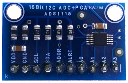
An ADC is a very handy addition because this alone opens you up to the world of analog components and gadgets that are otherwise not usable with the Raspberry Pi.
As part of this practical exercise, we are going to connect two potentiometers (also known as pots) to the ADS1115 and read in their values in Python. We will use these values to create a PWM signal by varying its duty cycle and frequency. We'll see the effects of varying these parameters by observing how it affects the LED and how the waveform changes in a program called PiScope, which is a part of the PiGPIO family of utilities.
To perform the following exercise, remember we need the electronic components listed in the Technical requirements section at the start of this chapter, including an ADS1115 breakout module. The ADS1115 is a common and powerful analog-to-digital converter that connects to its master (in our case, a Raspberry Pi) using I2C.
Here are the core specifications of the ADS1115 pulled from its datasheet that we require for our exercise:
- Working voltage: 2 to 5 volts (so we know it will work with the Raspberry Pi's 3.3-volt logic)
- Interface: I2C
- Default I2C address: 0x48
The terminals on the ADS1115 are as follows:
- Vcc & GND: Power for the device.
- SCL: Clock signal, used to synchronize communication between the master and slave.
- SDA: Data signal, used to send data between the Raspberry Pi and the ADS1115.
- ADDR: This terminal can be used to change the default address if required.
- ALTR: Alert signal for advanced usage (we won't be needing this).
- A0 - A3: Analog input channels (we will connect Pots to A0 and A1).
First, let's start by building the circuit we require on our breadboard.
Building the ADS1115 ADC circuit
Let's build our breadboard circuit for this chapter's exercise. We will build our circuits in a series of steps, starting with placing the core components as illustrated in the following diagram:
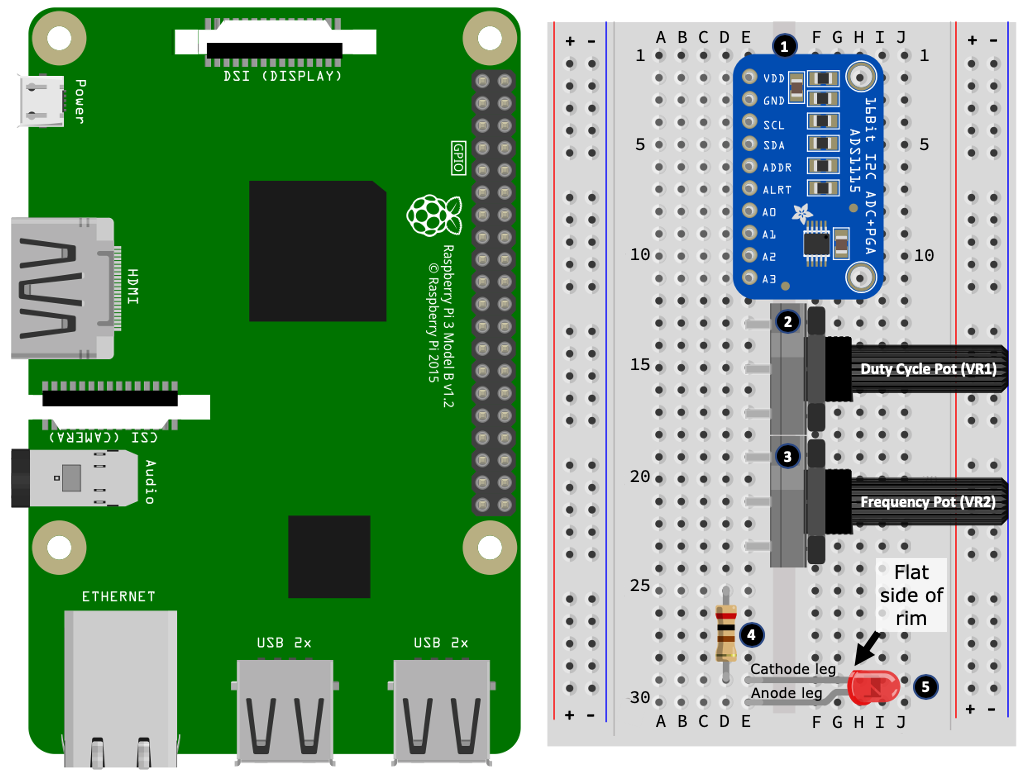
Here is how to lay out the component on your breadboard. The following step numbers match the numbered black circles in Figure 5.4:
- Position the ADS1115 on your breadboard.
- Position potentiometer VR1 on your breadboard. The illustrated potentiometers are full-size potentiometers. If you have a different size, their leg configuration may span fewer breadboard holes.
- Position the potentiometer VR2 on your breadboard.
- Position the resistor on your breadboard.
- Position the LED on your breadboard, paying attention to ensure that its cathode leg shares the same row as the resistor (illustrated at holes D29 and E29).
Next, we wire up the ADS1115 as illustrated here:

Here are the steps to follow. This time, the following step numbers match the numbered black circles in Figure 5.5:
- Connect the Raspberry Pi +3.3 volt pin to the breadboard positive power rail.
- Connect the VDD terminal on the ADS1115 to the breadboard positive power rail.
- Connect the GND terminal on the ADS1115 to the breadboard negative power rail.
- Connect the Raspberry Pi GND pin to the breadboard negative power rail.
- Connect the SCL pin on your Raspberry Pi to the SCL terminal on the ADS1115.
- Connect the SDA pin on your Raspberry Pi to the SDA terminal on the ADS1115.
Finally, we wire up the LED, resistor, and potentiometers, as illustrated in the following diagram:
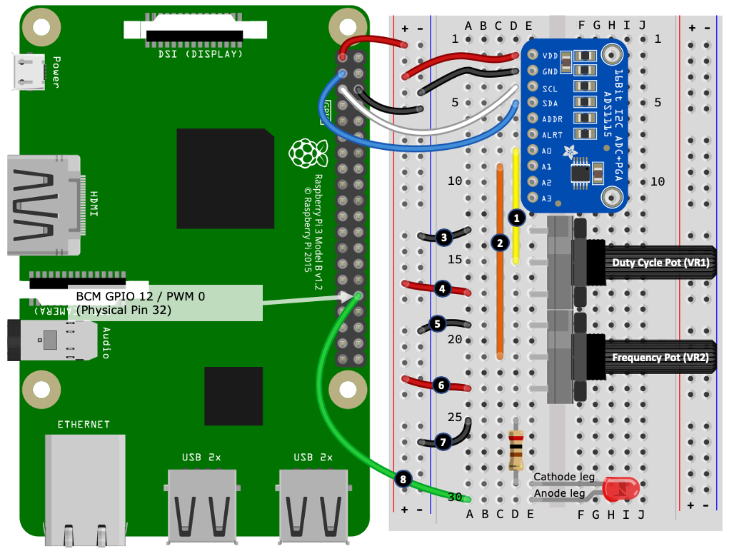
Here are the steps to follow. This time, the following step numbers match the numbered black circles in Figure 5.6:
- Connect the A0 terminal on the ADS1115 to the center leg of potentiometer VR1.
- Connect the A1 terminal on the ADS1115 to the center leg of potentiometer VR2.
- Connect the upper leg of potentiometer VR1 to the breadboard negative power rail.
- Connect the lower leg of potentiometer VR1 to the breadboard positive power rail.
- Connect the upper leg of potentiometer VR2 to the breadboard negative power rail.
- Connect the lower leg of potentiometer VR2 to the breadboard positive power rail.
- Connect the upper leg of the resistor to the breadboard negative power rail.
- Connect the anode leg of the LED to BCM GPIO 12 / PWM 0 on your Raspberry Pi.
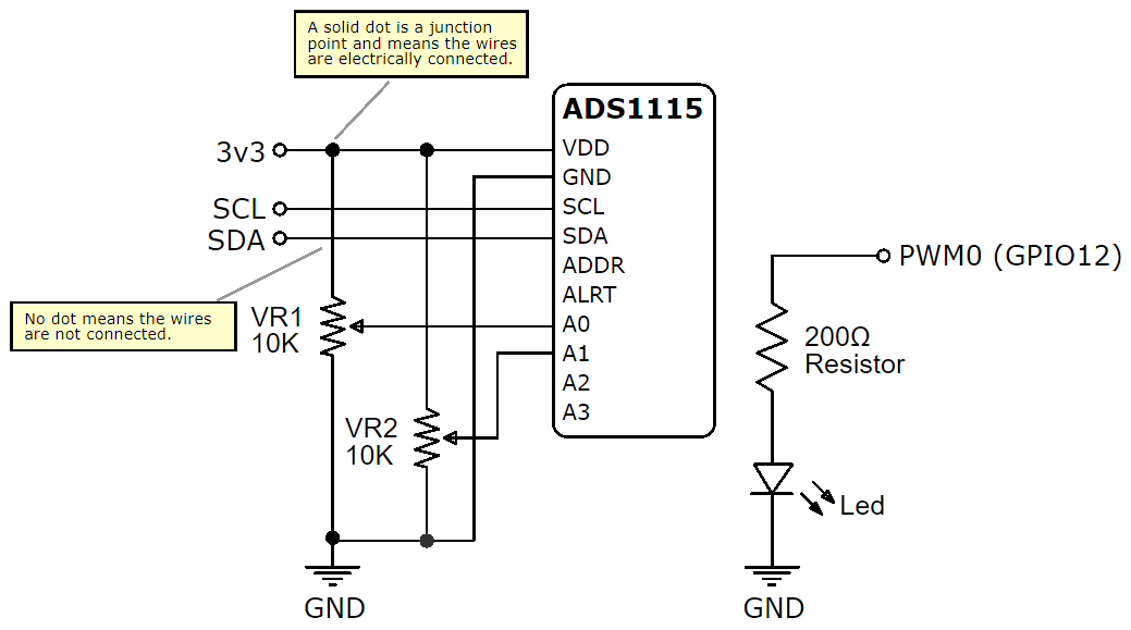
Well done! You have now completed this circuit. For your reference, a semantic diagram depicting the breadboard circuit is shown in Figure 5.7.
I encourage you to trace around this semantic diagram while referring back to the breadboard layout to understand how the lines and labels on the diagram relate back to the pictured components and wires on the breadboard. Investing the time to understand how paired schematic diagrams and breadboard circuits relate to one another will assist and increase your ability to create breadboard layouts directly from a schematic diagram:
With the circuit complete, let's check that the ADS1115 can be seen by our Raspberry Pi.
Making sure the ADS1115 is connected to your Raspberry Pi
I2C devices are identified to their master (that is, our Raspberry Pi) by a unique address, and the default address for the ADS1115 is 0x48. Since I2C devices are addressed, multiple devices can share the same I2C channels (pins) on a Raspberry Pi.
Raspbian OS contains the i2cdetect utility that queries the Raspberry Pi's I2C interface for connected devices. Run the following in a Terminal:
$ i2cdetect -y 1
The -y option assumes we answer yes to any prompts. 1 is the I2C bus number. It's always 1 on the Raspberry Pi 3 or 4. We expect to see the output like this:
     0  1  2  3  4  5  6  7  8  9  a  b  c  d  e  f
 00:          -- -- -- -- -- -- -- -- -- -- -- -- --
 10: -- -- -- -- -- -- -- -- -- -- -- -- -- -- -- --
 20: -- -- -- -- -- -- -- -- -- -- -- -- -- -- -- --
 30: -- -- -- -- -- -- -- -- -- -- -- -- -- -- -- --
 40: -- -- -- -- -- -- -- -- 48 -- -- -- -- -- -- --
 50: -- -- -- -- -- -- -- -- -- -- -- -- -- -- -- --
 60: -- -- -- -- -- -- -- -- -- -- -- -- -- -- -- --
 70: -- -- -- -- -- -- -- --
The fact that we see 48 (hex address) is indicative that our Raspberry Pi has detected the ADS1115. If you do not get this result, check your wiring and make sure I2C has been enabled as described in Chapter 1, Setting Up Your Development Environment.
Now that we have verified that our ADS1115 is visible to our Raspberry Pi, let's proceed and read the two potentiometers as analog input.
Reading analog input with the ADS1115
Now that we have our ADS1115 connected to our Raspberry Pi, it's time to learn how to use it to read in analog values, specifically the analog values created by our two potentiometers. We will use these analog values shortly to produce a PWM signal, which in turn will control the brightness of our LED.
The code we are about to cover can be found in the file chapter05/analog_input_ads1115.py. Please review this file before continuing.
- Start by running the program in a Terminal:
(venv) $ python analog_input_ads1115.py
- You should receive a stream of output similar to the following (your value and volts numbers will be different):
 Frequency Pot (A0) value=3 volts=0.000 Duty Cycle Pot (A1) value= 9286 volts=1.193
 Frequency Pot (A0) value=3 volts=0.000 Duty Cycle Pot (A1) value= 9286 volts=1.193
 ...truncated...
- Turn the two potentiometers and watch the output change—specifically, you will notice the numbers reported for value and volts change. The value and voltage will be in the following ranges:
-
- value in the range 0 to 26294 (or thereabouts)
- voltage in the range 0 to 3.3 volts (or thereabouts)
The output will be as follows:
 Frequency Pot (A0) value=3 volts=0.000 Duty Cycle Pot (A1) value= 9286 volts=1.193
 Frequency Pot (A0) value=4 volts=0.001 Duty Cycle Pot (A1) value=26299 volts=3.288
 ...truncated...
As we'll discuss more in Chapter 6, Electronics 101 for the Software Engineer, analog input is about reading voltages, in our case here, between 0 volts/GND (our reference voltage) and +3.3 volts. The integer value is the raw output of the ADS1115, and what its maximum value is will depend on how the ADS1115 IC is configured (we're using the defaults). The voltage value is derived from this raw value using math based on the ADS1115 configuration. All of the gooey details are in the ADS1115 datasheet and the library source code if you are interested.
As you adjust the two potentiometers, do not get worried if the exact ends of these ranges do not marry up precisely to 0 and 3.3 volts, or if the values randomly twitch a little. This fuzzy result is expected when we deal with analog electronics.
Next, we will examine the code.
Understanding the code
Now that we have seen the basic operation of our ADS1115 ADC, it's time to have a look at the accompanying code to understand how we query the ADS1115 in Python to get analog readings. What we learn below will lay the foundations for the analog interfacing programs that we will see in part 3 of this book.
We will commence our code walk-through with the imports.
Imports
There are two ways we can use the ADS1115 with our Raspberry Pi with Python:
- Read the ADS1115 datasheet and use a lower-level I2C such as SMBus to implement the data protocol used by the device.
- Find a ready-made Python library available through PyPi that we can install using pip.
There are several ready-made Python modules available to use with the ADS1115. We are using the Adafruit Binka ADS11x5 ADC library that we installed through requirement.txt at the start of this chapter:
import board                                      # (1)
import busio
import adafruit_ads1x15.ads1115 as ADS
from adafruit_ads1x15.analog_in import AnalogIn
Starting at line (1), we see the board and busio imports from Circuit Python (Blinka), while the last two imports starting with adafruit are from the Adafruit ADS11x5 ADC library and are used to configure the ADS1115 module and read its analog input, which we are going to look at next.
ADS1115 setup and configuration
At line (2) in the following code block, we use the busio import to create an I2C interface with Circuit Python/Blika. The board.SLC and board.SDA parameters indicate we are using the dedicated I2C channel (alternative functions of GPIO 2 and 3) on the Raspberry Pi:
# Create the I2C bus & ADS object.
i2c = busio.I2C(board.SCL, board.SDA)      # (2)
ads = ADS.ADS1115(i2c)
Next, we create an instance of ADS.ADS1115 using the pre-configured I2C interface and assign it to the ads variable. From this point forward in the code, when we interact with our ADS1115 module, we will use this instance.
Next, let's consider the global variables.
Global variables
At line (3) in the following code snippet, we start with a few quasi-constants defining the maximum and minimum voltages we expect to receive through the analog input. When you ran the code previously, your end range voltages probably were not exactly 0 and 3.3 volts. This occurrence is expected, and it can make a program feel like the Pots do not reach the ends of their rotation. The value assigned to A_IN_EDGE_ADJ is used to compensate for this in code. We will revisit this variable in the next section:
A_IN_EDGE_ADJ = 0.002                     # (3)
MIN_A_IN_VOLTS = 0 + A_IN_EDGE_ADJ
MAX_A_IN_VOLTS = 3.3 - A_IN_EDGE_ADJ
Next, starting at line (4), we create two AnalogIn instances relating to the A0 and A1 inputs of the ADS1115 that are connected to our Pots. It's through these variables that we determine how much a user has rotated our frequency and duty cycle potentiometers:
frequency_ch = AnalogIn(ads, ADS.P0)  #ADS.P0 --> A0    # (4)
duty_cycle_ch = AnalogIn(ads, ADS.P1) #ADS.P1 --> A1
Next, we come to the program's entry point where we will read our analog inputs.
Program entry point
Our program continuously loops, reading our analog input values for each pot and prints formatted output to the Terminal.
At line (5), we see how to access the integer value from the frequency pot using frequency_ch.value and the voltage value using frequency_ch.voltage:
if __name__ == '__main__':
   try:
       while True:
           output = ("Frequency Pot (A0) value={:>5} volts={:>5.3f} "
                     "Duty Cycle Pot (A1) value={:>5} volts={:>5.3f}")
           output = output.format(frequency_ch.value,          # (5)
                                  frequency_ch.voltage,
                                  duty_cycle_ch.value,
                                  duty_cycle_ch.voltage)
           print(output)
           sleep(0.05)
   except KeyboardInterrupt:
       i2c.deinit()                                            # (6)
Finally, notice that the program is wrapped in a try/except block that will capture Ctrl + C so that we can perform a clean-up using i2c.deinit().
Now that we have seen how to read analog input using our ADS1115, next, we will integrate the LED.
Using PWM to control an LED
Now we will add the LED into the code, only we'll be doing this differently to what we've done in previous chapters. The purpose of the LED for this exercise is to visually see the effects of changing the duty cycle and frequency characteristics of PWM. We will use the analog inputs of the two Pots to define the PWM duty cycle and frequency.
The code we discuss in this section extends the analog code example we just covered in chapter05/analog_input_ads1115.py to use PiGPIO to create a hardware PWM signal.
Two additional source code files are provided with this book that implement hardware-timed PWM using PiGPIO and software PWM using RPi.GPIO:
- chapter05/pwm_hardware_timed.py
- chapter05/pwm_software.py
Their overall code is similar, with the differences being the methods and input parameters used to invoke PWM. We will revisit these files again in the upcoming section, Visualizing software and hardware-timed PWM.
The code we are about to cover can be found in the chapter05/pwm_hardware.py file. Please review this file before continuing:
- Run the program in a Terminal and observe the output:
(venv) $ python pwm_hardware.py
Frequency 0Hz Duty Cycle 0%
... truncated ...
Frequency 58Hz Duty Cycle 0%
Frequency 59Hz Duty Cycle 0%
... truncated ...
- Adjust the Pots until the frequency reads 60 Hz and the duty cycle reads 0%. The LED should not be lit. The LED is unlit because the duty cycle is at 0%, so GPIO 12 (PWM0) is always low. Very slowly turn the duty cycle Pot to increase the duty cycle and observe the LED slowly increase in brightness. At a 100% duty cycle, GPIO 12 (PWM0) is always high 100% of the time and the LED is at its full brightness.
- Rotate the duty cycle dial until it reads less than 100% (for example, 98%), and then adjust the frequency dial. The LED blinks on and off at this frequency. As you lower the frequency toward zero, the LED blinks slower. For most people, at around 50-60 Hz, the LED will be blinking so fast that it appears to be just on. Remember that if the duty cycle is 0% or 100%, the frequency dial does not work! That's because at either end of the duty cycle, the PWM signal is fully off or on—it's not pulsing and hence frequency has no meaning.
Let's examine the code that makes this work.
Understanding the code
This example is using the hardware PWM features offered by PiGPIO. The ADS1115-related code is the same as our previous example, so we will not cover it again here. We'll start by looking at the additional global variables.
Global variables
At line (1) and (2) in the following code block, we define two variables for the minimum and maximum duty cycle and frequency values. These values come from the API documentation for the PiGPIO hardware_PWM() method, which we will see in use shortly:
MIN_DUTY_CYCLE = 0            # (1)
MAX_DUTY_CYCLE = 1000000
MIN_FREQ = 0                  # (2)
MAX_FREQ = 60 # max 125000000
We have capped MAX_FREQ to 60 Hz for our demonstration so our human eyes can observe the effects in the LED.
Next, we have a custom function to map value ranges.
Range mapping function
At line (3), we have a function named map_value():
def map_value(in_v, in_min, in_max, out_min, out_max):           # (3)
    """Helper method to map an input value (v_in)
       between alternative max/min ranges."""

    v = (in_v - in_min) * (out_max - out_min) / (in_max - in_min) + out_min
    if v < out_min: v = out_min elif v > out_max: v = out_max
    return v
The purpose of this method is to map an input range of values into another range of values. For example, we use this function to map the analog input voltage range 0-3.3 volts into a frequency range 0-60. You will frequently use a value-mapping function like this when working with analog inputs to map raw analog input values into more meaningful values for your code.
Next, we are ready to create the PWM signal.
Generating the PWM signal
This next code fragment is found in the main while loop.
At lines (4) and (5), we are reading in the voltage values from the frequency and duty cycle Pots, before using the map_value() function to convert the voltage range of 0-3.3 volts into our desired frequency and duty cycle ranges we saw defined as global variables. Notice that we are also formatting the duty cycles as a percentage value for display purposes:
frequency = int(map_value(frequency_ch.voltage,                # (4)
                          MIN_A_IN_VOLTS, MAX_A_IN_VOLTS,
                          MIN_FREQ, MAX_FREQ))

duty_cycle = int(map_value(duty_cycle_ch.voltage,              # (5)
                           MIN_A_IN_VOLTS, MAX_A_IN_VOLTS,
                           MIN_DUTY_CYCLE, MAX_DUTY_CYCLE))

duty_cycle_percent = int((duty_cycle/MAX_DUTY_CYCLE) * 100)

pi.hardware_PWM(LED_GPIO_PIN, frequency, duty_cycle)           # (6)
At line (6), we use pi.hardware_PWM() to use the Raspberry Pi's PWM hardware to generate a PWM signal on the LED's pin.
Now that we have seen the effects of varying the frequency and duty cycles on an LED, we will perform an exercise to visualize a PWM signal with a logic analyzer.
Visually exploring PWM with PiScope
Let's do an exercise and see the PWM waveform in a logic analyzer, which is a piece of equipment used to visualize electronic signals. While the general principles behind PWM are technically simple, to aid learning when starting out, it can be helpful to visualize what a PWM signal looks like and observe how it changes visually as its duty cycle and frequency change.
PiGPIO contains a software logic analyzer we can use for this purpose. Now, I need to point out that it's a basic software logic analyzer and in no way compares to professional-grade equipment, however, for our example and education, it will work a treat and cost us nothing.
Let's download, install, and run PiScope. Here are the steps to follow:
- First, we must install PiScope. Run the following commands to download, compile, and install PiScope:
# Download and install piscope
$ cd ~
$ wget abyz.me.uk/rpi/pigpio/piscope.tar
$ tar xvf piscope.tar
$ cd PISCOPE
$ make hf
$ make install
- Run PiScope with the following command:
$ piscope
I'd recommend shutting down any resource-heavy applications before starting PiScope and performing this exercise. The following screenshots do not show all GPIOs like yours would by default because I've turned some off via the menu Misc | GPIOs. If you, too, turn off GPIOs from the display, remember to leave on SDA (GPIO 2) and/or SCL (GPIO 3) for this exercise as this creates a continuous input signal for PiScope, which keeps the display moving in time. Without this continuous input, PiScope pauses the display when there is no signal input so our example will keep pausing the display at the duty cycle or frequencies of 0, which will make the demonstration feel clunky.
- Make sure the chapter05/pwm_hardware.py program is running in a Terminal.
- Slowly turn the duty cycle and frequency dials and observe how the PWM signal changes on row number 12. Keeping our frequency range very low (for example, 0 to 60 Hz) means we can observe the PWM signal easily in the PiScope logic analyzer:

The preceding screenshot shows a 25% duty cycle at 10 Hz. If you examine the last row in the screenshot, you will notice that GPIO 12 is high for 25% of a single cycle and low for 75%.
The following screenshot shows a 75% duty cycle at 10 Hz. If you examine the last row in the screenshot, you will notice that GPIO 12 is high for 75% of a single cycle and low for 25%:

We have now seen what a PWM signal waveform looks like visually using PiScope, which is a free and basic software logic analyzer provided by the developer of PiGPIO. Our primary purpose behind visualizing PWM signals as an exercise was to provide a visual aid to help you to understand PWM and its duty cycle and frequency properties.
In practice, when you are starting out and integrating with basic electronics, you probably won't need a logic analyzer or even the need to visualize signals. However, as you advance your knowledge and as you need to debug electronic integration problems at the electronics level, I hope this basic introduction to the use of logic analyzers proves useful and points you in the right direction for further inquiries.
Next, we'll point you toward the Python source files that demonstrate alternative PWM techniques.
Visualizing software and hardware-timed PWM
Our code examples from the previous sections, Using PWM to control an LED, and Visually exploring PWM with PiScope, both created a PWM signal using your Raspberry Pi's PWM hardware. Accompanying the code for this chapter and listed in the following table are alternative implementations that demonstrate the use of hardware-timed and software-generated PWM signals. You may recall that we discussed these alternatives back in the section entitled Creating PWM signals:
|
File |
Details |
|---|---|
|
pwm_hardware.py |
This is hardware PWM using PiGPIO (this is the code we've seen in this chapter). You must use a PWM hardware GPIO pin 12, 13, 18, or 19. |
|
pwm_hardware_timed.py |
This is a hardware-timed PWM using PiGPIO. This will work with any GPIO pin. |
|
pwm_software.py |
This is software PWM using RPi.GPIO (PiGPIO does not provide software PWM). This will work with any GPIO pin. |
Functionally, these examples are the same in that they will change your LED's brightness, and I predict that you will find that hardware and software PWM perform similarly. As you turn the frequency Pot's dial, the change to the LED and PiScope will feel smooth, while the hardware-timed PWM will feel a little chunky. This is because the hardware-timed frequencies (in PiGPIO) must be 1 of 18 predetermined values so the frequency progression as you adjust the pot is not incremental and linear, but instead jumps to/from the next predefined frequency. You'll see these predefined frequencies in an array in pwm_hardware-timed.py.
As mentioned previously, software PWM is the least reliable method of producing PWM signals because it is susceptible to distortion if your Raspberry Pi's CPU gets busy.
You can try to create and visualize PWM distortion with these steps:
- Run pwm_software.py and set the duty cycle to high (for example, 98%) and the frequency to 60 Hz. Do not use a 100% duty cycle because this is a fully-on state and you would visually get a horizontal line, not repeating square waveforms.
- Start a resource-intensive program on your Raspberry Pi—something that will put a load on the CPU. For example, try closing and relaunching the Chrome web browser.
- If you closely observe the LED, it may flicker occasionally as the PWM signal is distorted. Alternatively, you may be able to observe the waveform distort in PiScope, as indicated by the arrows in the following screenshot. You will notice the width of the bars is not uniform when that the signal is distorting:

Well done. You've just completed a detailed practical exercise using an ADS1115 to extend your Raspberry Pi so that you can also interface it with analog electronics. Along the way, you also learned how to produce a PWM signal with Python, saw the effects of varying this signal on an LED, and observed the signal visually with PiScope.
Summary
Well done on getting this far, as there has certainly been a lot to get our heads around! As a recap, we explored common numbering schemes for referencing GPIO pins and reviewed popular GPIO libraries for Python. We also looked at the various interfacing methods used to connect electronics to your Raspberry Pi and performed a practical exercise to add an ADC to your Raspberry Pi and use it to visually explore PWM concepts with an LED and the PiScope logic analyzer.
Your understanding of the fundamental concepts we explored and experimented with during this chapter will help you to understand how your Raspberry Pi interfaces to electronic components and devices and has provided you with a first-hand appreciation of how we interact with analog components (for instance, our potentiometers) and complex devices (that is, our ADS1115). We will be using and building on many of these fundamentals as we progress through the remainder of this book.
This chapter has been largely software library and code-focused. However, in the next chapter, Electronics 101 for the Software Engineer, we will turn our attention to electronic concepts and common circuits that are used to interface electronics to a Raspberry Pi.
Questions
As we conclude, here is a list of questions for you to test your knowledge regarding this chapter's material. You will find the answers in the Assessments section of the book:
- What serial communication interface allows devices to be daisy-chained?
- You have an I2C device but do not know its address. How can you find it?
- You have started using a new GPIO Python library for the first time but can't seem to get any GPIO pins to work. What do you need to check?
- You are using PiGPIO on Windows with Remote GPIO to drive a remote Raspberry Pi. Now, you try to install a third-party device driver library but it's failing to install under Windows However, you find it installed successfully on the Raspberry Pi. What is the likely problem?
- True or false: The Raspberry Pi has pins for both 3.3 volts and 5 volts, so you can use either voltage when working with GPIO pins?
- You have created a robot that uses servos. During simple testing, everything seemed fine. However, now that you have finished, you notice the servos randomly twitch. Why?
- When the robot's servos move, you notice a lightning bolt icon on your monitor or display is going blank. Why could this be happening?
Further reading
The GPIOZero website has a range of examples showing functionally equivalent examples using both GPIOZero and RPi.GPIO. This is a great introductory resource for understanding lower-level GPIO programming concepts and techniques:
The following links contain additional material concerning the interfaces and concepts that we have discussed in this chapter:
- SPI interface: https://en.wikipedia.org/wiki/Serial_Peripheral_Interface
- I2C interface: https://en.wikipedia.org/wiki/I%C2%B2C
- 1-wire interface: https://en.wikipedia.org/wiki/1-Wire
- PWM: https://en.wikipedia.org/wiki/Pulse-width_modulation
- Potentiometers: https://en.wikipedia.org/wiki/Potentiometer
- ADS1115 datasheet: http://www.ti.com/lit/gpn/ads1115