In the previous chapter, we covered how to measure temperature, humidity, light, and moisture. In this chapter, we will turn our attention to the control of motors and servos, which are common devices for creating physical movement and motion. The core concepts, circuits, and code you will learn in this chapter will open up a world of physical automation and robotics using your Raspberry Pi.
We will be learning how Pulse Width Modulation (PWM) is used to set the angle of a servo, and how we use an H-Bridge IC to control the direction and speed of a DC motor. We will look at stepper motors and how they can be controlled for precise movement.
Here is what we will cover in this chapter:
- Using PWM to rotate a servo
- Using an H-Bridge IC to control a motor
- Introduction to stepper motor control
Technical requirements
To perform the exercises in this chapter, you will need the following:
- Raspberry Pi 4 Model B
- Raspbian OS Buster (with desktop and recommended software)
- Minimum Python version 3.5
These requirements are what the code examples in this book are based on. It's reasonable to expect that the code examples should work without modification on Raspberry Pi 3 Model B or a different version of Raspbian OS as long as your Python version is 3.5 or higher.
You will find this chapter's source code in the chapter10 folder in the GitHub repository available at https://github.com/PacktPublishing/Practical-Python-Programming-for-IoT.
You will need to execute the following commands in a terminal to set up a virtual environment and install the Python libraries required for the code in this chapter:
$ cd chapter10              # Change into this chapter's folder
$ python3 -m venv venv      # Create Python Virtual Environment
$ source venv/bin/activate  # Activate Python Virtual Environment
(venv) $ pip install pip --upgrade        # Upgrade pip
(venv) $ pip install -r requirements.txt  # Install dependent packages
The following dependency is installed from requirements.txt:
- PiGPIO: The PiGPIO GPIO library (https://pypi.org/project/pigpio)
The electronic components we will need for this chapter's exercises are as follows:
- 1 x MG90S hobby servo (or an equivalent 3-wire 5-volt hobby servo). Reference datasheet: https://www.alldatasheet.com/datasheet-pdf/pdf/1132104/ETC2/MG90S.html
- 1 x L293D integrated circuit (IC) (make sure it has the D – that is, L293D, not L293). Reference datasheet: https://www.alldatasheet.com/datasheet-pdf/pdf/89353/TI/L293D.html
- 1 x 28BYJ-48 stepper motor (5 volts, 64 steps, 1:64 gearing). Note: 28BYJ-48 comes in 5-volt and 12-volt varieties and different configuration steps and gearings. Reference datasheet: https://www.alldatasheet.com/datasheet-pdf/pdf/1132391/ETC1/28BYJ-48.html
- 2 x size 130 (R130) DC motor rated 3-6 volts (ideally with a stall current < 800 mA), or alternate DC motor with compatible voltage and current ratings
- External power source – at a minimum, a 3.3 V/5 V breadboard-mountable power supply
Let's commence by learning how to use a servo with our Raspberry Pi, Python, and PiGPIO.
Using PWM to rotate a servo
Common servomotors, or servos, are internally geared motors that allow you to rotate its shaft to a precise angle within a 180-degree arc. They are a core component of industrial robots, and toys alike, and we're all familiar with hobby servos found in toys such as radio-controlled cars, planes, and drones.
Pictured in Figure 10.1 are a full-size hobby-style servo, a micro servo, and a set of header pins, which are useful to help connect a servo to a breadboard, which we will need to do later in this section as we build our circuit:

The great feature of servos is that they are essentially a Plug'n'Play style device – after we connect them to the power supply, we just need to send them a PWM signal that encodes the angle we want the servo to rotate to, and presto! We're done. No ICs, no transistors, or any other external circuitry. What's even better is that servo control is so common that many GPIO libraries – including PiGPIO – include convenience methods for their control.
Let's start our servo exploration by connecting one to our Raspberry Pi.
Connecting a servo to your Raspberry Pi
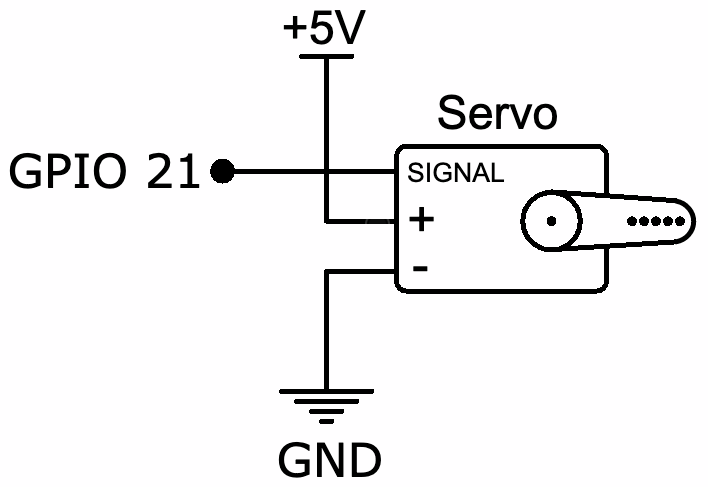
Our first task for our servo example is to wire it up to a power source and our Raspberry Pi. A schematic representing this wiring is shown here:
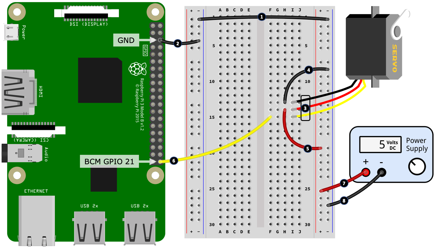
Let's get started wiring our servo using a breadboard, as shown:
Before we step through the wiring procedure, first I want to briefly discuss the wire colors coming out of a servo. While servo wire colors are somewhat standard, they can vary between different manufacturers and servos. Use the following pointers when connecting your servo at steps 4, 5, and 6. If your servo has colored wires that I do not list in the following list, you will need to consult the datasheet for your servo.
Common servo wire colors are as follows:
- The brown or black wire connects to GND
- The red wire connects to +5-volts
- The orange, yellow, white, or blue wire is the signal/PWM input wire that connects to a GPIO pin
Here are the steps to follow to create your breadboard build. The step numbers match the numbers in the black circles in Figure 10.3:
- Connect the left-hand side and right-hand side negative power rails together.
- Connect a GND pin on your Raspberry Pi to the left-hand side negative power rail.
- Connect the servo into the breadboard. As mentioned previously and shown in Figure 10.1, you will need a set of header pins (or alternatively, male-to-male jumper cables) to connect your servo to your breadboard.
- Connect the black wire (negative/GND) from the servo to the negative rail of the right-hand side power rail.
- Connect the red wire (5-volt power) from the servo to the positive rail of the right-hand side power rail.
- Connect the signal wire from the servo to GPIO 21 on your Raspberry Pi.
- Connect the positive output terminal of a 5-volt power supply to the positive rail of the right-hand side power rail.
- Connect the negative output terminal of the power supply to the negative rail of the right-hand side power rail.
You will need to use an external 5-volt power source (steps 7 and 8) to power your servo. A small servo such as an MG90S uses ~200mA as it rotates with no load on the shaft/horn (the horn is the arm connected to the shaft of the servo), and ~400+mA maximum current if you attach a heavy load to the horn or you forcefully stop a rotation. Drawing this current directly from your Raspberry Pi's 5-volt pin may be enough to cause it to reset.
Before we get into some code, we'll take a quick look at how PWM is used to control a servo. This will give you some background on what's happening when we get to the code.
How a servo is controlled using PWM
Servos typically require around a 50 Hz PWM signal (some variation around 50 Hz is okay, but we'll stick with 50 Hz as this is the common reference point), and a pulse width between 1.0 milliseconds and 2.0 milliseconds that determines the angle of rotation. The relation between pulse widths, duty cycles, and angle is illustrated in Figure 10.4. Don't worry if all this does not sink in just yet. It should become more clear as we see our servo in action and review our servo-related code in the next section:

We have not covered pulse width in relation to our earlier coverage of PWM; however, it's just another way of describing the duty cycle.
Here is an example:
- If we have a PWM signal at 50 Hz (that is, 50 cycles per second), then this means that 1 PWM cycle takes 1 / 50 = 0.02 seconds, or 20 ms.
- Thus, a pulse width of 1.5 ms expressed as a duty cycle is 1.5 ms / 20 ms = 0.075, multiplied by 100 gives us a duty cycle of 7.5%.
To work backward, we have the following:
- A duty cycle of 7.5% divided by 100 is 0.075. Then, 0.075 x 20 ms = 1.5 ms – that is, a 1.5 ms pulse width.
If you'd prefer a formula to relate pulse width, frequency, and duty cycle, here it is:

To convert back, we have the following:

Okay, enough with the math. Let's run and review the Python code to make our servo move.
Running and exploring the servo code
The code we are about to run can be found in the chapter10/servo.py file. I recommend reviewing the source code before proceeding so that you have an overall idea about what the file contains.
When you run the code found in the chapter10/servo.py file, your servo should rotate left and then right several times.
Let's look at the code, starting with some pulse width variables defined at line 1:
LEFT_PULSE  = 1000   # Nano seconds          # (1)
RIGHT_PULSE = 2000
CENTER_PULSE = ((LEFT_PULSE - RIGHT_PULSE) // 2) + RIGHT_PULSE  # Eg 1500
These pulse widths represent our servo's extreme left and right rotation.
These values of LEFT_PULSE = 1000 and RIGHT_PULSE = 2000 are the perfect world values that you will see sighted often. In reality, you may need to make slight adjustments to these variables to get the full rotation out of your servo. For example, my test servo needed the LEFT_PULSE = 600 and RIGHT_PULSE = 2450 values to achieve full rotation. You'll know if you have adjusted too far if your servo motor stays engaged and makes a groaning noise when it is at full left or right rotation. If this happens, disconnect power immediately to prevent damage to the servo and readjust your values.
At line 2, we define the MOVEMENT_DELAY_SECS= 0.5 variable, which we need later to add a delay between servo movements:
  # Delay to give servo time to move
  MOVEMENT_DELAY_SECS = 0.5            # (2)
As you work with servos and send them a PWM rotation signal, you will find that they behave asynchronously. That is, the code does not block until the servo finishes its rotation. If we intend to make many rapid servo movements that you want to complete in full, we must add a short delay to ensure the servo has time to complete the rotation. An example of this is found in the sweep() function we will cover shortly. The delay of 0.5 seconds is only a suggestion, so feel free to experiment with different numbers.
Starting at line 3, we define three basic functions to control our servo:
 def left():                                               # (3)
       pi.set_servo_pulsewidth(SERVO_GPIO, LEFT_PULSE)

 def center():
       pi.set_servo_pulsewidth(SERVO_GPIO, CENTER_PULSE)

 def right():
       pi.set_servo_pulsewidth(SERVO_GPIO, RIGHT_PULSE)
The left() function simply sets the PWM pulse width to LEFT_PULSE on the servo's GPIO pin using the PiGPIO set_servo_pulsewidth() method. This is a convenience function for servo control offered by PiGPIO as a practical alternative to using the set_PWM_dutycycle() and set_PWM_frequency() methods that we have seen in many previous chapters. We'll say more about these methods after we've reviewed the code.
The center() and right() functions perform their respective equivalent action to left().
If you rotate your servo to a specified angle and try to move the horn with your hand, you will notice that the servo resists the change. This is because the servo is continuously receiving (at a rate of 50 Hz) the last pulse set via set_servo_pulsewidth(), so it resists any attempt to change its set position.
If you set the servo's pulse width to zero, as we do in the idle() function shown at line 4, you will now find that you can freely rotate the servo by hand with little force. When my test servo was idle (or at rest), it used approximately 6.5 mA:
   def idle():                                      # (4)
      pi.set_servo_pulsewidth(SERVO_GPIO, 0)
So far, we've seen how to make the servo rotate to the left, center, and right, but what if we want to rotate it to a particular angle? Easy(-ish), we just need a little math, as shown in the angle() function at line 5:
  def angle(to_angle):                                   # (5)
      # Restrict to -90..+90 degrees
      to_angle = int(min(max(to_angle, -90), 90))

      ratio = (to_angle + 90) / 180.0                    # (6)
      pulse_range = LEFT_PULSE - RIGHT_PULSE
      pulse = LEFT_PULSE - round(ratio * pulse_range)    # (7)

      pi.set_servo_pulsewidth(SERVO_GPIO, pulse)
The angle() function takes an angle in the range -90 to +90 degrees (0 degrees being center), works out the ratio of our input angle relative to the 180-degree range of our servo at line 6, before deriving the corresponding pulse width at line 7. This pulse width is then sent to the servo and it will adjust its angle accordingly.
Finally, we encounter the sweep() function at line 10. This is the function that provided the left/right sweeping movement of the servo when you ran this code:
 def sweep(count=4):                        # (10)
      for i in range(count):
          right()
          sleep(MOVEMENT_DELAY_SECS)
          left()
          sleep(MOVEMENT_DELAY_SECS)
In this function, we see the use of sleep(MOVEMENT_DELAY_SECS), which is necessary to give the servo time to complete each rotation request due to the asynchronous nature of servos. If you were to comment out the two sleep() calls, you will find that the servo rotates to the left and stops. This happens because as the for loop iterates (without sleep()), each left() call overrides the previous right() call, and so on, and it's left() that is called last before the loop completes.
This now concludes our servo examples. The knowledge you have learned together with the code examples will provide you with everything you need to start using servos in your own projects! Our focus has been on using angular motion servos; however, the core of what you have learned will also be adaptable with some trial and error and experimenting (mostly around identifying the correct pulse widths) for use with a continuous rotation servo, which I'll briefly mention in the next section.
Let's conclude our discussion of servos with a brief consideration of the different types of servos.
Different types of servos
Our example used a common 3-wire, 180-degree angular servo. While this is a very common type of servo, there are other variations as well, including continuous rotation servos, servos with more than three wires, and special purpose servos:
- Continuous rotation servos: Have 3 wires and work on the same PWM principles as a 3-wire angular servo, except the PWM pulse width determines the rotational direction (clockwise/counter-clockwise) and speed of the servo.
- 4-wire servos: These come with one set of three wires and a fourth loose wire. This fourth wire is an analog output of the servo that can be used to detect the angle. It's useful if you need to know your servo's resting angle when you start your program.
- Special purpose or heavy-duty industrial use servos: Have different wiring configurations and usage requirements – for example, they may not have the internal circuitry to decode PWM signals and require the user to supply and create the circuit to perform this function.
We have now learned how common hobby-style servos work, and also discovered how to set their angle of rotation in Python using PWM. In the next section, we will learn more about DC motors and how to control them using an IC known as an H-Bridge.
Using an H-Bridge IC to control a motor
In Chapter 7, Turning Things On and Off, we learned how to use a transistor to turn a DC motor on and off, and we also saw how to control the motor's speed using PWM. One limitation of our single transistor circuit was that the motor only rotated in one direction. In this section, we will explore a way to let us spin our motor in both the forward and backward directions – using what is known as an H-Bridge circuit.
If you search around sites such as eBay for an H-Bridge module, you will identify many ready-made modules for the same purpose that we will cover in this section. What we will do is build a replica module on our breadboard. Once you have your breadboard replica working and understand how it works, you will be in a position to understand the construction of these ready-made modules.
We can create an H-Bridge to drive our motor in a few ways:
-
Just use a pre-built module (modules and ICs may also be called or labeled motor drivers, or motor controllers). This is the easiest way.
-
Create an H-Bridge circuit using discrete components – for example, four transistors, many diodes, a handful of resistors, and a lot of wire to connect them all. This is the hardest way.
-
Use an IC (that internally combines all the necessary discrete parts).
We will opt for the last option and use an L293D, which is a common and low-cost H-Bridge IC that we can use to build a motor controller circuit.
Here are the basic specifications for the L293D extracted from its datasheet:
- Continuous current of 600 mA, 1.2 A peak/pulsed. As a reminder, we explored motors and current use in Chapter 7, Turning Things On and Off.
- It can control a motor with a voltage between 4.5 volts and 36 volts.
- It includes internal fly-back diodes, so we do not need to add our own. This is what the D means in L293D. If you need a refresher on fly-back diodes, please also see Chapter 7, Turning Things On and Off.
- It comprises two channels, so it is capable of driving two DC motors simultaneously.
Let's build our circuit to control our motors.
Building the motor driver circuit
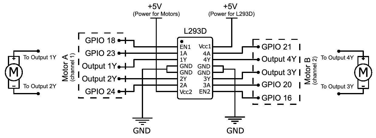
In this section, we will build our H-Bridge circuit that we will use to control two DC motors. The following schematic describes the circuit we will create. While this circuit looks busy, most of our work will be simply connecting the legs of the L293D IC to our Raspberry Pi, power source, and motors:
As there are a lot of wire connections to get through, we will build this circuit on our breadboard in four parts.
Let's get started with the first part, as illustrated in the following diagram:

Here are the steps to follow to start our breadboard build. The step numbers match the numbers in black circles in Figure 10.6:
- Start by placing the L293D IC in your breadboard, making sure that that IC is orientated correctly with pin/leg 1 facing toward the top of your breadboard. Pin 1 of an IC is commonly indicated by a small circular indentation or dot beside the pin. In our illustration, this dot is white for visibility; however, it'll most likely be the same color as the casing on your IC. In the absence of a dot, there is also commonly a cutout section on one end of an IC. Pin 1 is the top-left pin when you hold the IC with the cutout facing away from you.
- Connect a 5-volt pin on your Raspberry Pi to the positive rail of the left-hand side power rail.
- Connect a GND pin on your Raspberry Pi to the negative rail of the left-hand side power rail.
- Connect GPIO 18 to pin 1 of the L293D.
- Connect GPIO 23 to pin 2 of the L293D.
- Connect GPIO 24 to pin 7 of the L293D.
- Connect a jumper lead to pin 3 of the L293D. The other end of this lead (labeled Output 1Y) is not connected to anything for the moment.
- Connect a jumper lead to pin 6 of the L293D. The other end of this lead (labeled Output 2Y) is not connected to anything for the moment.
- Using a jumper wire, connect pin 4 and pin 5 on the L293D together.
- Finally, connect pin 4 and pin 5 of the L293D to the negative rail of the left-hand side power rail.
The bulk of the work we just performed involved the wiring of channel 1 of the L293D. As a reminder, the L293D has two output channels, which, for the content in this section, means we can control two DC motors.
If you refer back to Figure 10.6, you will notice the wires (placed at steps 7 and 8) comprise the output for channel 1. Later in this section, we will attach a motor to these wires. Furthermore, in the diagram, you will notice that GPIOs 18, 23, and 24 are labeled as Channel 1 Control GPIOs. We will learn how these GPIOs are used to control the larger channel 1 motor when we discuss the code that accompanies this circuit.
Moving on, the next part of our build largely involves wiring up channel 2 of the L293D. This is more or less a mirror of the wiring we just performed:

Here are the steps to follow to complete the second part of our breadboard build. The step numbers match the numbers in black circles in Figure 10.7:
- Connect pin 16 of the L293D to the positive rail of the left-hand side power rail. This 5-volt connection to pin 16 provides the power for the IC's internal circuitry – it is not the power source for the channel outputs (that is our motors). We will connect the external power source to the IC in part 3 of the build for powering the channels' motors.
- Connect GPIO 16 to pin 9 of the L293D.
- Connect GPIO 20 to pin 10 of the L293D.
- Connect GPIO 21 to pin 15 of the L293D.
- Connect a jumper lead to pin 14 of the L293D. The other end of this lead (labeled Output 4Y) is not connected to anything for the moment.
- Connect a jumper lead to pin 11 of the L293D. The other end of this lead (labeled Output 3Y) is not connected to anything for the moment.
- Using a jumper wire, connect pin 12 and pin 13 on the L293D together.
- Finally, connect pin 12 and pin 13 of the L293D to the negative rail of the right-hand side power rail.
Now that we have wired the channel 2 output, our third task is to connect the external power supply:

Here are the steps to follow to complete the third part of our breadboard build. The step numbers match the numbers in black circles in Figure 10.8:
- Connect the positive output terminal of your power supply to the positive rail of the right-hand side power rail.
- Connect the negative output terminal of your power supply to the negative rail of the right-hand side power rail.
- Connect pin 8 of the L293D to the positive rail of the right-hand side power rail. Pin 8 of the L293D provides the input power used to drive the output channels.
- Finally, using a jumper wire, connect the negative rails of the left-hand side and right-hand side power rails.
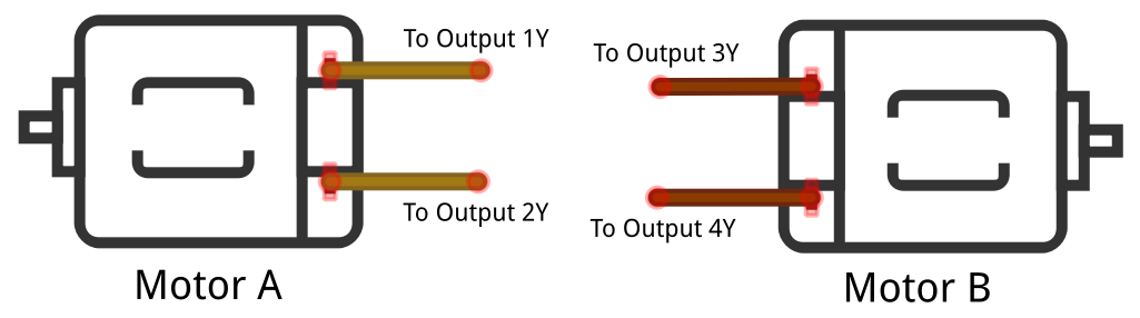
This is our breadboard layout complete. However, there is one final task where we connect our motors. Following the example in the following diagram, you can connect a motor to each output channel:
Well done! That was a lot of wiring. I imagine that the tangle of wires you now have on your breadboard does not look nearly as graceful as the illustrations! Please do take the time to double-check your wirings for this circuit, as an incorrectly placed wire will prevent the circuit from working as intended.
During our circuit build, in part 3, step 3, we connected an external 5-volt power source to pin 8 of the L293D. This is the power used to drive each output channel, and hence our motors. If you ever wish to use motors that require a voltage different to 5 volts, you can alter this supply voltage to suit your needs, subject to the condition that the source voltage for the L293D must be within the range of 4.5 volts to 36 volts. Also remember (as mentioned at the start of this section) that your motors should not draw more than a 600 mA continuous current (fully on) or 1.2 A peak current (for instance, when using PWM, which we will cover when we get to the code).
Once you have created your breadboard circuit and connected your motors, we will run the example code and discuss how it works.
Running the example H-Bridge code to control a motor
Now that you have created your H-Bridge driver circuit and connected your motors, let's run the code that will make the motors spin.
There are two files for this section, and they can be found in chapter10/motor_class.py and chapter10/motor.py. Run the code found in chapter10/motor.py and your motors will turn on, change speeds, and change direction.
When you have confirmed that your circuit works with the example code, we will next proceed and discuss the code. Since the L293D can drive two motors, the common code has been abstracted out into motor_class.py, which is imported and used by motor.py to drive our two individual motors.
We'll start by looking at motor.py.
motor.py
Starting at line 1, we import PiGPIO and the Motor class defined in the motor_class.py file, before defining several variables describing how we are connecting the L293D to our Raspberry Pi's GPIO pins:
import pigpio                    # (1)
from time import sleep
from motor_class import Motor

# Motor A
CHANNEL_1_ENABLE_GPIO = 18       # (2)
INPUT_1Y_GPIO = 23
INPUT_2Y_GPIO = 24

# Motor B
CHANNEL_2_ENABLE_GPIO = 16       # (3)
INPUT_3Y_GPIO = 20
INPUT_4Y_GPIO = 21
Referring back to Figure 10.3 and Figure 10.4, if we consider the Motor A (channel 1) side of the circuits, we see that the logic pins are connected to GPIOs 23 and 24 at line 2 – INPUT_1Y_GPIO = 23 and INPUT_2Y_GPIO = 24. These logic pins (together with the enable pin that we will cover shortly) are used to set the state and rotational direction of the motor. The truth table for these states is shown as follows.
This table was sourced from the L293D datasheet and reformatted and supplemented to match our code and circuit:
|
Row # |
Enable GPIO |
Logic 1 GPIO |
Logic 2 GPIO |
Motor Function |
|
1 |
HIGH or > 0% duty cycle |
Low |
High |
Turns right |
|
2 |
HIGH or > 0% duty cycle |
High |
Low |
Turns left |
|
3 |
HIGH or > 0% duty cycle |
Low |
Low |
Break |
|
4 |
HIGH or > 0% duty cycle |
High |
High |
Break |
|
5 |
LOW or 0% duty cycle |
N/A |
N/A |
Motor off |
The L293D has two enable pins – one for each channel (that is, one for each motor) – for instance, CHANNEL_1_ENABLE_GPIO = 18 at line 3 in the preceding code. The enable pins are like a master switch for each channel. When the enable pin is set high, it turns the associated channel on, thus applying power to the motor. Alternatively, we can control the speed of a motor if we instead pulse the enable pin using PWM. We'll see the code that works with the logic and enables pins shortly when we explore the motor_class.py file.
Next, we will create a single instance of pigpio.pi(), as shown in line 4, and then we will create two instances of Motor to represent our two physical motors:
pi = pigpio.pi()                 # (4)
motor_A = Motor(pi, CHANNEL_1_ENABLE_GPIO, INPUT_1Y_GPIO, INPUT_2Y_GPIO)
motor_B = Motor(pi, CHANNEL_2_ENABLE_GPIO, INPUT_3Y_GPIO, INPUT_4Y_GPIO)
After we have created the motor_A and motor_B classes, we perform a few actions with these class to control the motors, as shown in the following code, starting at line 5 – this is what you witnessed in the previous section when you ran the code:
 print("Motor A and B Speed 50, Right")
 motor_A.set_speed(50)                                # (5)
 motor_A.right()
 motor_B.set_speed(50)
 motor_B.right()
 sleep(2)

 #... truncated ...

 print("Motor A Classic Brake, Motor B PWM Brake")
 motor_A.brake()                                      # (6)
 motor_B.brake_pwm(brake_speed=100, delay_millisecs=50)
 sleep(2)
Take note of the braking at line 6 and observe the motors. Did one motor brake better than the other? We will discuss this further when we cover the two brake functions toward the end of the next section.
Let's move on and look at motor_class.py. This is where the code that integrates our Raspberry Pi with the L293D is found.
motor_class.py
First, we see the Motor class definition and its constructor:
class Motor:

  def __init__(self, pi, enable_gpio, logic_1_gpio, logic_2_gpio):

    self.pi = pi
    self.enable_gpio = enable_gpio
    self.logic_1_gpio = logic_1_gpio
    self.logic_2_gpio = logic_2_gpio

    pi.set_PWM_range(self.enable_gpio, 100) # speed is 0..100       # (1)

    # Set default state - motor not spinning and
    # set for right direction.
    self.set_speed(0) # Motor off                                   # (2)
    self.right()
At line 1, we are defining the PiGPIO PWM duty cycle range for the enable pin to be in the range 0..100. This defines the maximum range value (that is, 100) that we can use with the set_speed() function that we'll come to shortly.
The range 0..100 means we have 101 discrete integer PWM steps, which maps conveniently to a 0% to 100% duty cycle. If you specify a higher number, this does not mean more duty cycles (or more motor speed); it just changes the granularity of the steps – for example, the default PWM range of 0..255 gives us 256 discrete steps, where 255 = 100% duty cycle.
Our constructor finishes by initializing the motor to be off (zero speed) and defaults the motor to the right rotational direction, as shown in the preceding code at line 2.
Next, we encounter several functions that we use to make our motor(s) spin. We see at line 3 and line 4 the right() and left() methods, which alter the high/low states of the logic pins of the L293D, according to rows 1 and 2 in the preceding table:
 def right(self, speed=None):           # (3)
     if speed is not None:
         self.set_speed(speed)

     self.pi.write(self.logic_1_gpio, pigpio.LOW)
     self.pi.write(self.logic_2_gpio, pigpio.HIGH)


 def left(self, speed=None):           # (4)
     if speed is not None:
         self.set_speed(speed)

     self.pi.write(self.logic_1_gpio, pigpio.HIGH)
     self.pi.write(self.logic_2_gpio, pigpio.LOW)
We can check whether our motor is set to rotate left or right by querying the current states of the logic pins, as shown in is_right() at line 5. Notice that the queried GPIO states in is_right() match the states set in right():
   def is_right(self):                              # (5)
       return not self.pi.read(self.logic_1_gpio)   # LOW
              and self.pi.read(self.logic_2_gpio)   # HIGH
We see the use of set_PWM_dutycycle() in the set_speed() method in the following code at line 6, where we set the speed of our motor by pulsing the enable pin of the L293D. Pulsing the enable pin is done using the same basic principles we used back in Chapter 7, Turning Things On and Off, when we pulsed a transistor to set our motor's speed:
    def set_speed(self, speed):                      # (6)
        assert 0<=speed<=100
        self.pi.set_PWM_dutycycle(self.enable_gpio, speed)
You can stop the motor by setting the speed to 0, which effectively is cutting off the motor's power (0% duty cycle = pin low).
Moving forward, we find two methods named brake() and brake_pwm() at lines 7 and 8, which can be used to stop the motor quickly. The difference between braking and stopping a motor by cutting its power (that is, set_speed(0)) is that set_speed(0) allows the motor to slow down gradually over time – which is the state at row 5 in the preceding table:
    def brake(self):                # (7)
        was_right = self.is_right() # To restore direction after braking

        self.set_speed(100)
        self.pi.write(self.logic_1_gpio, pigpio.LOW)
        self.pi.write(self.logic_2_gpio, pigpio.LOW)
        self.set_speed(0)

        if was_right:
            self.right()
        else:
            self.left()
When you ran this code in the previous section, and if you experiment with the two brake functions on your own, my guess is that you will find brake() does not work well (if at all), while the brake_pwm() function does:
    def brake_pwm(self, brake_speed=100, delay_millisecs=50):    # (8)
        was_right = None # To restore direction after braking
        if self.is_right():
            self.left(brake_speed)
            was_right = True
        else:
            self.right(brake_speed)
            was_right = False
        sleep(delay_millisecs / 1000)
        self.set_speed(0)
        if was_right:
            self.right()
        else:
            self.left()
Let's discuss why we have defined two different braking methods and why one works better than the other.
The implementation of brake() is the classic way a motor brake is implemented, where both logic GPIOs are set high or low together, as in rows 3 or 4 in the preceding table. The catch, however, is that the performance of this logic can vary depending on the IC you are using (how it's constructed internally), your motor, and the voltage and current use are using. For our example, we are using a small motor (with no load on its shaft), small voltage and currents, and an L293D IC. The net of all this is that classic braking does not work well, if at all.
The break_pwm(reverse_speed, delay_secs) implementation takes a different and more reliable approach to braking by applying a small and opposite voltage to the motor. You can use the brake_speed and delay_millisecs parameters to tune the braking if required – too little speed and delay and the brake will not work, too much and the motor will reverse direction.
Congratulations! You have just learned how to operate a servo and master the control of a DC motor in terms of speed and the direction of braking. The circuits, code, and skills you have just acquired can be adapted to many applications where you need to create motion and angular movement – for example, a robotic car or arm. You could even use these skills to retrofit motorized toys and other motorized gadgets and make them controllable by your Raspberry Pi.
If you would like to extend your knowledge further, you might like to explore how to create an H-Bridge circuit from individual components – such as transistors, resistors, and diodes. While there are various ways to accomplish this circuit, we covered the core basics in terms of concepts and components between this chapter and our use of transistors back in Chapter 7, Turning Things On and Off.
Well done! We covered a lot in this section as we learned how to use an L293D H-Bridge to make a DC motor spin, reverse direction, and brake. In the next section, we will look at an alternative use of the L293D and see how to use it to control a stepper motor.
Introduction to stepper motor control
Stepper motors are a unique type of motor in terms of their precision and torque. Similar to a DC motor, a stepper motor can rotate in both directions continuously, while they can be precisely controlled similar to a servo.
In the following diagram is a 28BYJ-48 stepper motor, together with headpins that can be used to connect the motor to a breadboard:

Stepper motor theory and practice can get complex quickly! There are different forms and types of stepper motors and many variables, such as stride angles and gearing, that all need to be accounted for, plus various ways to wire and control them. We can't possibly cover all these parameters here, nor can we go into the low-level details of how stepper motors work.
Instead, we will cover the practical operation of a common and readily available stepper motor, a 28BYJ-48. Once you understand the basic principles as they apply to a 28BYJ-48, you will be well-positioned to broaden your knowledge of stepper motors.
The basic specifications for our reference 28BYJ-48 are as follows:
- 5 volts (make sure your stepper is 5 volts because the 28BYJ-48 also comes in 12 volts).
- A stride angle of 64, a 1:64 gearing ratio, giving 64 x 64 = 4,096 steps per 360 degree revolution.
Using the stride angle, gearing ratio, and sequence, we can calculate the number of logical steps needed to rotate our stepper motor 360 degrees: 64 x 64 / 8 = 512 steps.
Next, we will connect our stepper motor to our Raspberry Pi.
Connecting the stepper motor to the L293D circuit
To connect our stepper motor to our Raspberry Pi, we are going to reuse our L293D circuit, as shown in Figure 10.8 in the previous section. Here is what we need to do:

The following steps match the numbering shown in Figure 10.11. Remember that we are starting with the circuit you completed previously in the section entitled Building the motor driver circuit and shown in Figure 10.8:
- If you have not done so already, disconnect the two DC motors from the existing circuit.
- Connect the orange wire of your stepper motor to the wire labeled Output 4Y in Figure 10.8.
- Connect the yellow wire of your stepper motor to the wire labeled Output 3Y in Figure 10.8.
- Connect the pink wire of your stepper motor to the wire labeled Output 2Y in Figure 10.8.
- Connect the blue wire of your stepper motor to the wire labeled Output 1Y in Figure 10.8.
In our example scenario, we are using our L293D H-Bridge to drive our stepper motor as a bipolar stepper motor. You will come across the terms bipolar and unipolar in relation to stepper motors. These terms relate to how the motor is wired, and this influences how you will control them. A discussion of the differences between bipolar and unipolar stepper motors can quickly get complex; however, a simplified distinction at this stage of learning is as follows:
- A bipolar stepper motor requires a driving circuit that is capable of reversing the current flow.
- A unipolar stepper motor does not require a circuit that is capable of reversing the current flow.
In our example with bipolar wiring, we use an H-Bridge circuit because it is capable of reversing current flow to a coil (for example, this is how we made our DC motor reverse direction in the previous section).
With our stepper motor connected, we can continue on to control it with code.
Running and exploring the stepper motor code
The code we are about to run can be found in the chapter10/stepper.py file. I recommend reviewing the source code before proceeding so that you have an overall idea of what the file contains.
When you run the code found in the chapter10/stepper.py file, your stepper motor should rotate a complete 360 degrees in one direction, and then back again.
Starting at the top of the source file, we define all our GPIO variables, including our enable pins at line 1, plus variables starting at line 2 relating to our stepper motor coil wires. These wires must be identified and ordered correctly, as coil wire order matters!
CHANNEL_1_ENABLE_GPIO = 18                                # (1)
CHANNEL_2_ENABLE_GPIO = 16

INPUT_1A_GPIO = 23 # Blue Coil 1 Connected to 1Y          # (2)
INPUT_2A_GPIO = 24 # Pink Coil 2 Connected to 2Y
INPUT_3A_GPIO = 20 # Yellow Coil 3 Connected to 3Y
INPUT_4A_GPIO = 21 # Orange Coil 4 Connected to 4Y

STEP_DELAY_SECS = 0.002                                   # (3)
We will see later in code the use of STEP_DELAY_SECS at line 3 to add a slight delay in between coil steps. A higher delay will result in a slower rotation of the stepper motor's shaft; however, too small a number and the shaft may not rotate at all or the rotation may be erratic and stutter. Feel free to experiment with different delay values to suit your needs.
Next, starting at line 4, we group our coil GPIOs into a Python list (array) and initialize these GPIOs as outputs at line 5. We're storing the GPIOs in a list because we will be iterating over these GPIOs later when we use the rotate() function. We also have the off() function at line 6 that we use to turn off all the coils:
coil_gpios = [                             # (4)
    INPUT_1A_GPIO,
    INPUT_2A_GPIO,
    INPUT_3A_GPIO,
    INPUT_4A_GPIO
]

# Initialise each coil GPIO as OUTPUT.
for gpio in coil_gpios:                    # (5)
    pi.set_mode(gpio, pigpio.OUTPUT)

def off():
    for gpio in coil_gpios:                # (6)
       pi.write(gpio, pigpio.LOW) # Coil off

off() # Start with stepper motor off.
At line 7, we're setting the two enable GPIO pins HIGH in code because we are reusing the circuit from our previous DC motor control example. The alternative non-code approach would be to connect the L293D EN1 and EN2 pins directly to +5 volts (that is, pull them HIGH manually):
# Enable Channels (always high)
pi.set_mode(CHANNEL_1_ENABLE_GPIO, pigpio.OUTPUT)      # (7)
pi.write(CHANNEL_1_ENABLE_GPIO, pigpio.HIGH)
pi.set_mode(CHANNEL_2_ENABLE_GPIO, pigpio.OUTPUT)
pi.write(CHANNEL_2_ENABLE_GPIO, pigpio.HIGH)
Starting at line 8, we define two stepping sequences in a multi-dimension (2 x 2) array named COIL_HALF_SEQUENCE and COIL_FULL_SEQUENCE, and we thus encounter the parts of the code where it starts to become obvious that stepper motor control is more complex than DC motor or servo control!
A stepping sequence defines how we must turn on (energize) and off (not energized) each coil in the stepper motor to make it step. Each row in the sequence has four elements, each relating to a coil:
COIL_HALF_SEQUENCE = [             # (8)
    [0, 1, 1, 1],
    [0, 0, 1, 1],   # (a)
    [1, 0, 1, 1],
    [1, 0, 0, 1],   # (b)
    [1, 1, 0, 1],
    [1, 1, 0, 0],   # (c)
    [1, 1, 1, 0],
    [0, 1, 1, 0] ]  # (d)

COIL_FULL_SEQUENCE = [
    [0, 0, 1, 1],   # (a)
    [1, 0, 0, 1],   # (b)
    [1, 1, 0, 0],   # (c)
    [0, 1, 1, 0] ]  # (d)
A sequence with eight steps is known as a half-step sequence, while a full-step sequence has four rows and is a subset of the half-sequence (match up the (a), (b), (c), and (d) rows in the preceding code).
A half-sequence will give you more resolution (for example, 4,096 steps for a 360-degree revolution), while a full-step sequence will give you half the resolution (2,048 steps) but twice the stepping speed.
A stepping sequence for a stepper can usually be found in its datasheet – but not always, as our reference 28BYJ-48 datasheet mentioned in the Technical requirements section proves, so sometimes some research may be necessary.
Next, at line 9, we defined the global variable, sequence = COIL_HALF_SEQUENCE, to use a half-step sequence when stepping our motor. You can change this to sequence = COIL_FULL_SEQUENCE to use a full-step sequence – all other code remains the same:
sequence = COIL_HALF_SEQUENCE       # (9)
#sequence = COIL_FULL_SEQUENCE
At line 10, we have the rotate(steps) method, which is where all the magic happens, so to speak. Examining and understanding what this method does is the key to understanding how to control our stepper motor. The steps parameter can be a positive or a negative number to rotate the stepper motor in the reverse direction:
# For rotate() to keep track of the sequence row it is on.
sequence_row = 0

def rotate(steps):                              # (10)
    global sequence_row
    direction = +1
    if steps < 0:
        direction = -1
The core of the rotate() function is within the two for loops, starting at line 11:
# rotate(steps) continued...

    for step in range(abs(steps)):                # (11)
      coil_states = sequence[sequence_row]        # (12)
      for i in range(len(sequence[sequence_row])):
          gpio = coil_gpios[i]                    # (13)
          state = sequence[sequence_row][i]       # (14)
          pi.write(gpio, state)                   # (15)
          sleep(STEP_DELAY_SECS)
As the code loops for step iterations, we get the next coil state's form, sequence[sequence_row], at line 12 (for example, [0, 1, 1, 1]), before looping through and getting the corresponding coil GPIO at line 13, and its HIGH/LOW state at line 14. At line 15, we set the HIGH/LOW state of the coil with pi.write(), which makes our motor move (that is, step), before sleeping for a short delay.
Next, starting at line 16, the sequence_row index is updated based on the direction of rotation (that is, whether the steps parameter was positive or negative):
# rotate(steps) continued...

      sequence_row += direction            # (16)
      if sequence_row < 0:
          sequence_row = len(sequence) - 1
      elif sequence_row >= len(sequence):
          sequence_row = 0
At the end of this block of code, if there are more steps to complete, the code then goes back to line 11 for the next for steps in ... iteration.
Finally, at line 17, we come to the part of the code that made our stepper motor rotate when we ran the example. Remember, if you switch line 9 to be sequence = COIL_FULL_SEQUENCE, then the number of steps will be 2048:
if __name__ == '__main__':
    try:                                                   #(17)
        steps = 4096 # Steps for HALF stepping sequence.
        print("{} steps for full 360 degree rotation.".format(steps))
        rotate(steps) # Rotate one direction
        rotate(-steps) # Rotate reverse direction

    finally:
        off() # Turn stepper coils off
        pi.stop() # PiGPIO Cleanup
Congratulations! You have just completed a crash course on stepper motor control.
I understand that if you are new to steppers, there is some multi-dimensional thinking required and that you have been introduced to many concepts and terms that we have not been able to cover in detail. Stepper motors will take time to understand; however, once you grasp the basic process of controlling one stepper motor, then you are well on your way to understanding the broader concepts in more detail.
Summary
In this chapter, you learned how to use three common types of motors to create complex movement with your Raspberry Pi – a servo motor for creating an angular moment, a DC motor with an H-Bridge driver to create direction movement and speed control, and a stepper motor for precision movement. If you have grasped the general concepts of each of these types of motors, then you deserve a pat on the back! This is an achievement. While motors are simple in principle and their movement is something we take for granted daily in everyday appliances and toys, as you have discovered, there is a lot going on behind the scenes to make that movement occur.
What you have learned in this chapter, together with the example circuits and code, provides you with a foundation that you can use to start building your own applications where movement and motion are required. A simple and fun project could be to create a program to control a robotic car or robotic arm – you'll find DIY kits and robotic parts for cars and arms on sites such as eBay.
In the next chapter, we will explore ways we can measure distance and detect movement with our Raspberry Pi, Python, and various electronic components.
Questions
As we conclude, here is a list of questions for you to test your knowledge of this chapter's material. You will find the answers in the Assessments section of the book:
- Your servo does not rotate fully to the left or right. Why is this and how can you fix this?
- Your servo is groaning at one or both of its extreme left/right positions. Why?
- What advantage does an H-Bridge provide over a single transistor when controlling DC motors?
- You are using an L293D H-Bridge IC. You follow the instructions as per the datasheet but cannot get your motor to brake. Why?
- Why do your 5-volt motors spin slower when connected to an H-Bridge using an L293D compared to connecting the motor directly to a 5-volt source?
- You have a stepper motor that will not work – it vibrates, but will not turn. What could be the problem?
- Can you drive a stepper motor directly from four Raspberry Pis' GPIO pins?