In the previous chapter, we learned how to detect movement with a PIR sensor, as well as measure distances and detect movement with ultrasonic sensors and Hall-effect sensors.
In this chapter, we will discuss alternative ways of structuring our Python programs when we are working with electronic sensors (input devices) and actuators (output devices). We will cover the classic event-loop approach to programming, before moving on to more advanced approaches, including the use of threads in Python, the publisher/subscriber model, and finally, asynchronous I/O programming with Python.
I guarantee you that there are many, many blog posts and tutorials across the internet covering these topics; however, what we will cover in this chapter will be uniquely focused on practical electronic interfacing. Our approach in this chapter will involve creating a simple circuit with a push-button, a potentiometer, and two LEDs that we will make flash at different rates, and presenting four different coding approaches to make the circuit work.
Here is what we will cover in this chapter:
- Building and testing our circuit
- Exploring an event-loop approach
- Exploring a threaded approach
- Exploring a publisher-subscriber alternative
- Exploring an AsyncIO approach
Technical requirements
To perform the exercises in this chapter, you will need the following:
- Raspberry Pi 4 Model B
- Raspbian OS Buster (with desktop and recommended software)
- Minimum Python version 3.5
These requirements are what the code examples in this book are based on. It's reasonable to expect that the code examples should work without modification on Raspberry Pi 3 Model B or a different version of Raspbian OS as long as your Python version is 3.5 or higher.
You will find this chapter's source code in the chapter12 folder in the GitHub repository available at https://github.com/PacktPublishing/Practical-Python-Programming-for-IoT.
You will need to execute the following commands in a terminal to set up a virtual environment and install the Python libraries required for the code in this chapter:
$ cd chapter12              # Change into this chapter's folder
$ python3 -m venv venv      # Create Python Virtual Environment
$ source venv/bin/activate  # Activate Python Virtual Environment
(venv) $ pip install pip --upgrade        # Upgrade pip
(venv) $ pip install -r requirements.txt  # Install dependent packages
The following dependencies are installed from requirements.txt:
- PiGPIO: The PiGPIO GPIO library (https://pypi.org/project/pigpio)
- ADS1X15: The ADS1x15 ADC library (https://pypi.org/project/adafruit-circuitpython-ads1x15)
- PyPubSub: In-process messaging and events (https://pypi.org/project/PyPubSub)
The electronic components we will need for this chapter's exercises are as follows:
- 2 x red LEDs
- 2 x 200 Ω resistors
- 1 x push-button switch
- 1 x ADS1115 module
- 1 x 10k Ω potentiometer
To maximize your learning in this chapter, there are some assumptions made regarding pre-existing knowledge and experience:
- From an electronic interfacing perspective, I will assume that you have read the preceding 11 chapters of this book and are comfortable working with the PiGPIO and ADS1115 Python libraries featured throughout this book.
- From a programming perspective, I am assuming existing knowledge of Object-Oriented Programming (OOP) techniques and how they are implemented in Python.
- Familiarity with the concepts event-loop, threads, publisher-subscriber, and synchronous versus asynchronous paradigms will also be advantageous.
If any of the preceding topics are unfamiliar, you will find many online tutorials available covering these topics in great detail. Please see the Further reading section at the end of the chapter for suggestions.
Building and testing our circuit
I'm going to present the circuit and programs for this chapter in the form of a practical exercise. Let's pretend for a moment that we have been asked to design and build a gizmo that has the following requirements:
- It has two LEDs that blink.
- A potentiometer is used to adjust the rate that the LED(s) blink.
- When the program starts, both LEDs will blink at the same rate determined by the position of the potentiometer.
- A blinking rate of 0 seconds means an LED is off, while the maximum blinking rate of 5 seconds means an LED is on for 5 seconds, then off for 5 seconds, before repeating the cycle.
- A push-button is used to select which LED changes its blinking rate when the potentiometer is adjusted.
- When the push-button is pressed and held for 0.5 seconds, all LEDs synchronize to the same rate, determined by the potentiometer's position.
- Ideally, the program code should easily scale to support more LEDs with minimal coding effort.
Here is a scenario illustrating the gizmo's use:
- After applying power (and the program starts), all LEDs start to blink at a rate of 2.5 seconds because the potentiometer's dial is at the midpoint (50%) of its rotation.
- The user adjusts the potentiometer to make the first LED blink at a rate of 4 seconds.
- Next, the user briefly presses and releases the push-button so that the potentiometer will change the second LED's blinking rate.
- Now, the user adjusts the potentiometer so that the second LED blinks at a rate of 0.5 seconds.
- Finally, the user presses and holds the button down for 0.5 seconds to make both the first and second LED blink in unison at a rate of 0.5 seconds (the rate set by the potentiometer at step 4).
Now for the challenge I mentioned – before we get into this chapter's circuit and code, I challenge you to stop reading now and try to create a circuit and write a program that implements the preceding requirements.
I anticipate that you will encounter challenges and have questions about the best approach to take. There is no one best approach; however, by having your own implementation – whether it works or not – you will have something to compare and contrast with the four solutions that I will present during this chapter. I'm confident that if you have a go yourself first, then you will gain a deeper understanding and more insight. Hey, perhaps you'll create an even better solution!
If you need suggestions to help get you started, here they are:
- We first covered LEDs and push-buttons in Chapter 2, Getting Started with Python and IoT.
- We first covered potentiometers and analog input using an ADS1115 module in Chapter 5, Connecting Your Raspberry Pi to the Physical World.
When you are ready, we will look at a circuit that fulfills the aforementioned requirements.
Building the reference circuit
In Figure 12.1 is a circuit that meets the requirements we just listed. It has a push-button, a potentiometer in the form of a voltage divider connected to an ADS1115 analog-to-digital converter, and two LEDs connected by current limiting resistors. Adding additional LEDs will be as simple as wiring more LED and resistors pairs between GND and a free GPIO pin:

If you have not already created a similar circuit on your own, we will create this circuit now on your breadboard. We will build this circuit in three parts. Let's get started:
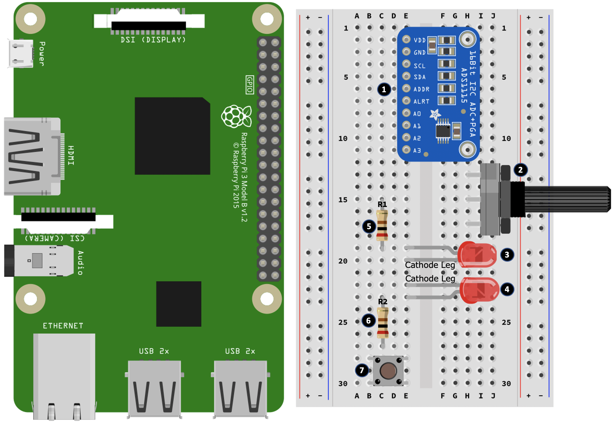
Here are the steps to follow to create the first part of our breadboard build where we place the components. The step numbers match the numbers in black circles in Figure 12.2:
- Place the ADS1115 module into your breadboard.
- Place the potentiometer into your breadboard.
- Place an LED into your breadboard, taking care to orientate the LED's legs as illustrated.
- Place a second LED into your breadboard, taking care to orientate the LED's legs as illustrated.
- Place a 200Ω resistor (R1) into your breadboard. One end of this resistor shares the same row as the anode leg of the LED placed in step 3.
- Place another 200Ω resistor (R2) into your breadboard. One end of this resistor shares the same row as the anode leg of the second LED you placed in step 5.
- Place the push-button into your breadboard.
Now that we have placed the components into the breadboard, let's start wiring them:
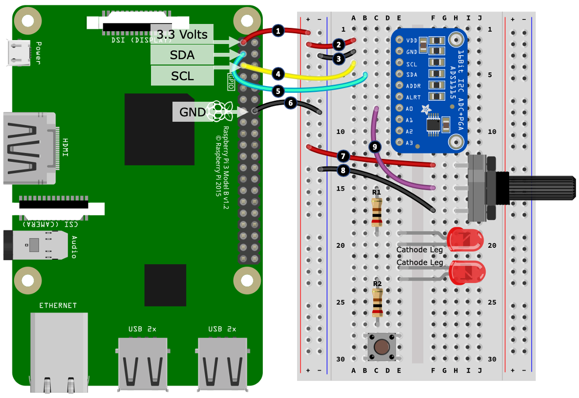
Here are the steps to follow to continue with the second part of our breadboard build. The step numbers match the numbers in black circles in Figure 12.3:
- Connect a 3.3-volt pin from your Raspberry Pi to the positive rail of the left-hand side power rail.
- Connect the Vdd terminal of the ADS1115 to the positive rail of the left-hand side power rail.
- Connect the GND terminal of the ADS1115 to the negative rail of the left-hand side power rail.
- Connect the SCL terminal of the ADS1115 to the SCL pin on your Raspberry Pi.
- Connect the SDA terminal of the ADS1115 to the SDA pin on your Raspberry Pi.
- Connect a GND pin on your Raspberry Pi to the negative rail of the left-hand side power rail.
- Connect an outer terminal of the potentiometer to the positive rail of the left-hand side power rail.
- Connect another outer terminal of the potentiometer to the negative rail of the left-hand side power rail.
- Connect the center terminal of the potentiometer to port A0 of the ADS1115.
Can you recall that the potentiometer in this configuration is creating a variable voltage divider? If not, you may want to revisit Chapter 6, Electronics 101 for the Software Engineer. Furthermore, if you would like a detailed refresher on the ADS1115 module, please refer to Chapter 5, Connecting your Raspberry Pi to the Physical World.
Let's continue with our build:
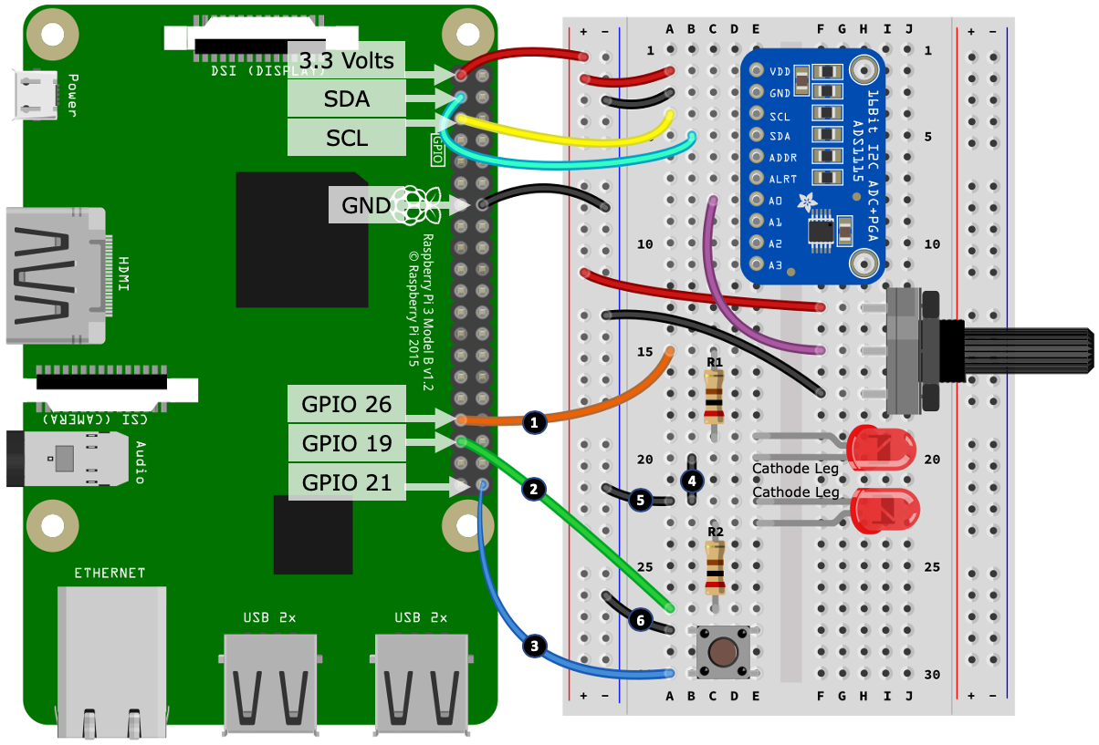
Here are the steps to follow to continue with the final part of our breadboard build. The step numbers match the numbers in black circles in Figure 12.4:
- Connect GPIO 26 from your Raspberry Pi to the 200 Ω resistor (R1).
- Connect GPIO 19 from your Raspberry Pi to the second 200 Ω resistor (R2).
- Connect GPIO 21 from your Raspberry Pi to one leg of the push-button.
- Connect the two cathode legs of the LEDs together.
- Connect the cathode legs of the LEDs to the negative rail of the left-hand side power rail.
- Connect the second leg of the push-button to the negative rail of the left-hand side power rail.
Now that we have finished our circuit build, we are ready to run the sample code to make the circuit work.
Running the examples
This chapter comes with four different versions of code that can work with the circuit shown previously in Figure 12.1. You will find the code in the chapter12 folder organized by version:
- chapter12/version1_eventloop is an event-loop-based example.
- chapter12/version2_thread is a thread and callback-based example.
- chapter12/version3_pubsub is a publisher-subscriber-based example.
- chapter12/version4_asyncio is an Asynchronous IO (AsyncIO)-based example.
All versions are functionally equivalent; however, they differ in their code structure and design. We will discuss each version in greater detail after we test our circuit.
Here are the steps to follow to run each version (starting with version 1) and test the circuit:
- Change to the version1_eventloop folder.
- Briefly look over the main.py source file, and any additional Python files in the folder, to get a feel for what they contain and how the program is structured.
- Run main.py in a terminal (remember to switch into the chapter's virtual environment first).
- Turn the potentiometer dial and observe the first LED's blinking rate changes.
- Press the button briefly.
- Turn the potentiometer dial and observe the second LED's blinking rate changes.
- Press and hold the button for 0.5 seconds, and observe that both LEDs now blink in unison at the same rate.
The following is an example of the terminal output you will receive:
(venv) $ cd version1_eventloop
(venv) $ python main.py
INFO:Main:Version 1 - Event Loop Example. Press Control + C To Exit.
INFO:Main:Setting rate for all LEDs to 2.5
INFO:Main:Turning the Potentiometer dial will change the rate for LED #0
INFO:Main:Changing LED #0 rate to 2.6
INFO:Main:Changing LED #0 rate to 2.7
INFO:Main:Turning the Potentiometer dial will change the rate for LED #1
INFO:Main:Changing LED #1 rate to 2.6
INFO:Main:Changing LED #1 rate to 2.5
# Truncated
INFO:Main:Changing LED #1 rate to 0.5
INFO:Main:Changing rate for all LEDs to 0.5
- Press Ctrl + C in your terminal to exit the program.
- Repeat steps 1 through 8 for version2_threads, version3_pubsub, and version4_asyncio.
You have just tested and glanced at the source code of four different programs (perhaps five, if you challenged yourself to create your own) that all achieve exactly the same end result but in different ways.
Now it's time to understand how these programs are built. Let's begin with the event-loop version of the program.
Exploring the event-loop approach
We will start our code exploration by discussing an event-loop-based approach to building the sample gizmo that we just tested in the previous section.
The code for the event-loop-based approach can be found in the chapter12/version1_eventloop folder. You will find one file named main.py. Please take the time now to stop and read through the code contained in main.py to get a basic understanding of how the program is structured and how it works. Alternatively, you could add breakpoints or insert print() statements into the code and run it again to understand how it works.
How did it go, and what did you notice? If you thought yuck or got lost in the web of loops, if statements, and state variables, then well done! This means you have invested the time to consider this approach and how the code is constructed.
What I mean by an event-loop approach is demonstrated in the code by the while True: loop abbreviated on line 1:
# chapter12/version1_eventloop
#
# Setup and initialization code goes before while loop.
#

if __name__ == "__main__":
    # Start of "Event Loop"
    while True:                                # (1)
      #
      # ... Main body of logic and code is within the while loop...
      #
      sleep(SLEEP_DELAY)
Granted, I could have used functions and even external classes to reduce the quantity (and possibly enhance the readability) of the code within the while loop, however, the overall design paradigm remains the same – the body of the program control is sitting in a perpetual loop.
You may have realized that this event-loop approach to programming has been used by many of the examples throughout this book. Three examples are as follows:
- When we wanted a timed event such as blinking an LED (Chapter 2, Getting Started with Python and IoT)
- Polling the DHT 11 or DHT 22 temperature/humidity sensor (Chapter 9, Measuring Temperature, Humidity, and Light Levels)
- Polling the ADS1115 analog-to-digital converter connected to a Light-Dependent-Resistor (LDR) (also Chapter 9, Measuring Temperature, Humidity, and Light Levels)
In this context, for a single focused example, event-loops make sense. They even make sense purely for convenience when you're hacking about and trying out new ideas and learning about a new actuator or sensor. However, as demonstrated by our version1_eventloop/main.py program, as soon as you add in multiple components (such as a potentiometer, two LEDs, and a push-button) and want to make them work together for a definite purpose, the code gets complex fast.
For instance, consider the following code on line 3, which is responsible for blinking all the LEDs, and remember that this block of code is evaluated once per loop iteration and is responsible for blinking every LED:
    #
    # Blink the LEDs.
    #
    now = time()                                               # (3)
    for i in range(len(LED_GPIOS)):
        if led_rates[i] <= 0:
            pi.write(LED_GPIOS[i], pigpio.LOW) # LED Off.
        elif now >= led_toggle_at_time[i]:
            pi.write(LED_GPIOS[i], not pi.read(LED_GPIOS[i])) # Toggle LED
            led_toggle_at_time[i] = now + led_rates[i]
Compare this to a vanilla alternative (similar to what we will see in other approaches), which at a moment's glance is significantly easier to understand:
   while True:
      pi.write(led_gpio, not pi.read(led_gpio)) # Toggle LED GPIO High/Low
      sleep(delay)
If you also consider the following block of code, starting on line 2, which is responsible for detecting button presses, then you find nearly 40 lines of code (in the actual main.py file) just to detect what the button is doing:
while True:
    button_pressed = pi.read(BUTTON_GPIO) == pigpio.LOW        # (2)

    if button_pressed and not button_held:
        # Button has been pressed.
        # ... Truncated ...
    elif not button_pressed:
        if was_pressed and not button_held:
            # Button has been released
            # ... Truncated ...
    if button_hold_timer >= BUTTON_HOLD_SECS and not button_held:
        # Button has been held down
        # ... Truncated ...

    # ... Truncated ...
You will count multiple variables at play – button_pressed, button_held, was_pressed, and button_hold_timer – that are all evaluated at every while loop iteration and are there primarily to detect a button-hold event. I'm sure you can appreciate that writing and debugging this code like this can be tedious and error-prone.
Now, I'm not saying that event-loops are a bad or wrong approach. They have their uses, they are needed, and, in essence, we create one every time we use a while loop or another looping construct – so the base ideal is everywhere, but it's just not an ideal approach to building complex programs, because this approach makes them harder to understand, maintain, and debug.
Whenever you find that your program is heading down this event-loop path, stop and reflect, because it might be time to consider refactoring your code to employ a different – and more maintainable – approach, such as a threaded/callback approach, which we will look at next.
Exploring a threaded approach
Now that we have explored an event-loop-based approach to creating our program, let's consider an alternative approach built using threads, callbacks, and OOP and see how this approach improves code readability and maintainability and promotes code reuse.
The code for the threaded-based approach can be found in the chapter12/version2_threads folder. You will find four files – the main program, main.py, and three class definitions: LED.py, BUTTON.py, and POT.py.
Please take the time now to stop and read through the code contained in main.py to get a basic understanding of how the program is structured and how it works. Then, proceed to review LED.py, BUTTON.py, and POT.py.
How did it go, and what did you notice? I'd guess that you found this version of the program (while reading through main.py) much quicker and easier to understand and noticed that there is no cumbersome and complex while loop, but instead a pause() call, which is necessary to stop our program from exiting, as summarized on line 3:
# chapter12/version2_threads/main.py
if __name__ == "__main__":                                       # (3)
        # Initialize all LEDs
        # ... Truncated ...

        # No While loop!
        # It's our BUTTON, LED and POT classes and the
        # registered callbacks doing all the work.
        pause()
In this program example, we have employed object-oriented techniques and componentized our program using three classes:
- A button class (BUTTON.py), which takes care of all the button logic
- A potentiometer class (POT.py), which takes care of all the potentiometer and analog-to-digital conversion logic
- A LED class (LED.py), which is responsible for making a single LED flash
By using an OOP approach, our main.py code is greatly simplified. Its role is now to create and initialize class instances and house the callback handlers and logic that make our program work.
Consider the following OOP approach for our push-button:
# chapter12/version2_threads/main.py
# Callback Handler when button is pressed, released or held down.
def button_handler(the_button, state):
    global led_index
    if state == BUTTON.PRESSED:                                 # (1)
        #... Truncated ...
    elif state == BUTTON.HOLD:                                  # (2)
        #... Truncated

# Creating button Instance
button = BUTTON(gpio=BUTTON_GPIO,
               pi=pi,
               callback=button_handler)
Compared to the button-handing code from the event-loop example, this is greatly simplified and much more readable – it's pretty explicit where and how this code is responding to the button pressed at line 1 and button holds on line 2.
Let's consider the BUTTON class, which is defined in the BUTTON.py file. This class is an enhancing wrapper around a PiGPIO callback function that turns the HIGH/LOW states of the button's GPIO pin into PRESSED, RELEASED, and HOLD events, as summarized in the following code at line 1 in BUTTON.py:
# chapter12/version2_threads/BUTTON.py
def _callback_handler(self, gpio, level, tick): # PiGPIO Callback  # (1)

     if level == pigpio.LOW: # level is LOW -> Button is pressed
         if self.callback: self.callback(self, BUTTON.PRESSED)

         # While button is pressed start a timer to detect
         # if it remains pressed for self.hold_secs
         timer = 0                                                 # (2)
         while (timer < self.hold_secs) and not self.pi.read(self.gpio):
             sleep(0.01)
             timer += 0.01

         # Button is still pressed after self.hold_secs
         if not self.pi.read(self.gpio):
             if self.callback: self.callback(self, BUTTON.HOLD)

     else: # level is HIGH -> Button released
         if self.callback: self.callback(self, BUTTON.RELEASED)
Compared to the button-handling code of the event-loop example, we did not introduce and interrogate multiple state variables to detect the button-hold event, but instead, this logic is reduced to a simple and linear approach at line 2.
Next, as we consider the POT class (defined in POT.py) and LED class (defined in LED.py), we will see threads come into our program.
The following is the thread run method for the POT class, which can be found in the POT.py source file, and illustrates, starting on line 1, the approach of intermediately polling the ADS1115 ADC to determine the potentiometer's position. We've seen this polling example several times already throughout this book, starting back in Chapter 5, Connecting Your Raspberry Pi to the Physical World, where we first discussed analog-to-digital conversion, the ADS1115 module, and potentiometers:
    # chapter12/version2_threads/POT.py
    def run(self):
        while self.is_polling:                              # (1)
            current_value = self.get_value()
            if self.last_value != current_value:            # (2)
                if self.callback:
                    self.callback(self, current_value)      # (3)
                self.last_value = current_value

            timer = 0
            while timer < self.poll_secs:  # Sleep for a while
                sleep(0.01)
                timer += 0.01

        # self.is_polling has become False and the Thread ends.
        self.__thread = None
The difference with our code here is that we are monitoring the ADC for voltage changes on line 2 (for example, when a user turns the potentiometer), and turning them into a callback on line 3, which you will have seen handled in main.py when you reviewed the source code in that file.
Let's now discuss how we are implementing the version2 LED-related code. As you are aware, the basic code pattern for blinking an LED on and off at a defined rate involves a while loop and a sleep statement. This is the approach taken in the LED class, as seen in the run() method on line 3 in LED.py:
# chapter12/version2_threads/LED.py
 def run(self):                                                    # (3)
     """ Do the blinking (this is the run() method for our Thread) """
     while self.is_blinking:
         # Toggle LED On/Off
         self.pi.write(self.gpio, not self.pi.read(self.gpio))

         # Works, but LED responsiveness to rate chances can be sluggish.
         # sleep(self.blink_rate_secs)

         # Better approach - LED responds to changes in near real-time.
         timer = 0
         while timer < self.blink_rate_secs:
             sleep(0.01)
             timer += 0.01

     # self.is_blinking has become False and the Thread ends.
     self._thread = None
I am sure you will agree that this is easier to understand than the approach taken by the event-loop approach we discussed in the previous section. It is important to remember, however, that the event-loop approach was working with and altering the blinking rate of all LEDs together in a single block of code, and within a single thread – the program's main thread.
Our version2 program example using the LED class with its own internal thread now means that we have multiple threads – one per LED – all making the LEDs blink independently to one another.
Can you think of any potential problems this may introduce? Okay, it might be obvious if you have read through the version2 source files – it's the synchronization of all LEDs to blink at the same rate in unison when the button is held for 0.5 seconds!
By introducing multiple threads, we have introduced multiple timers (that is, the sleep() statement), so each thread is blinking on its own independent schedule, and not from a common reference point in terms of a starting timebase.
This means that if we simply called led.set_rate(n) on multiple LEDs, while they would all blink on and off at the rate n, they would not necessarily blink in unison.
A simple solution to this issue is to synchronize the turning off of all LEDs before we start them blinking at the same rate. That is, we start them blinking from a common state (that is, off), and start them blinking together.
This approach is shown in the following code snippet starting at line 1 in LED.py. The core of the synchronization is achieved by the led._thread.join() statements on line 2:
    # chapter12/version2_threads/LED.py
    @classmethod                                           # (1)
    def set_rate_all(cls, rate):
        for led in cls.instances: # Turn off all LEDs.
            led.set_rate(0)

        for led in cls.instances:
            if led._thread:
                led._thread.join()                         # (2)

        # We do not get to this point in code until all
        # LED Threads are complete (and LEDS are all off)

        for led in cls.instances:  # Start LED's blinking
            led.set_rate(rate)
This is a good first pass at synchronization, and for practical purposes, it works well for our situation. As mentioned, all we are doing is ensuring our LEDs start blinking together from an off state at the same time (well, very, very, very close to the same time, subject to the time taken for Python to iterate through the for loops).
However, it must be noted that we are still dealing with multiple threads and independent timers to make our LEDs blink, so the potential for a time drift to occur is present. If this ever presented a practical issue, we would then need to explore alternative techniques to synchronize the time in each thread, or we could create and use a single class to manage multiple LEDs together (basically using the approach from the event-loop example, only refactoring it into a class and a thread).
The takeaway here regarding threads is that when you introduce threads to your applications, you can introduce timing issues that may be designed around or synchronized.
We've just seen how to create our sample gizmo program using OOP techniques, threads, and callbacks. We've seen how this approach results in easier to read and maintain code, and we also discovered the additional requirement and effort needed to synchronize threaded code. Next, we will look at the third variation of our program, which is based around a publisher-subscriber model.
Exploring the publisher-subscriber alternative
Now that we have seen an approach to creating our program using threads, callbacks, and OOP techniques, let's consider a third approach using a publisher-subscriber model.
The code for the publisher-subscriber approach can be found in the chapter12/version3_pubsub folder. You will find four files – the main program, main.py, and three class definitions: LED.py, BUTTON.py, and POT.py.
Please take the time now to stop and read through the code contained in main.py to get a basic understanding of how the program is structured and how it works. Then, proceed to review LED.py, BUTTON.py, and POT.py.
What you will have noticed is that the overall program structure (especially the class files) is very similar to the version2 thread/callback example that we covered in the previous heading.
You may also have realized that this approach is very similar in concept to the publisher/subscribing method employed by MQTT, which we discussed in detail in Chapter 4, Networking with MQTT, Python, and the Mosquitto MQTT Broker. The main difference is that in our current version3 example, our publisher-subscribing context is confined just to our program run-time environment, not a network-distributed set of programs, which was the scenario for our MQTT examples.
I have implemented the publishing-subscribing layer in version3 using the PyPubSub Python library, which is available from pypi.org and is installed using pip. We will not discuss this library in any detail, as the overall concepts and use of this type of library should already be familiar to you, and if not, I have no doubt that you will immediately understand what's going on once you review the version3 source code files (if you have not already done so).
Due to the similarity of the version2 (threaded approach) and version3 (publisher-subscriber approach) examples, we will not discuss each code file in detail, other than to point out that the core differences:
- In version2 (threaded), this is how our led, button, and pot class instances communicate with one another:
- We registered callback handlers in main.py on the button and pot class instances.
- button and pot send events (for example, a button press or potentiometer adjustment) via this callback mechanism.
- We interacted with the LED class instances directly using the set_rate() instance method and the set_rate_all() class method.
- In version3 (publisher-subscriber), here is the intra-class communication structure and design:
- Every class instance is very loosely coupled.
- There are no callbacks.
- We do not interact with any class instances directly after they are created and registered with PyPubSub.
- All communication between classes and threads occurs using the messaging layer provided by PyPubSub.
Now, to be honest, our gizmo program does not benefit from a publisher-subscriber approach. My personal preference is to adopt the callback version for a small program like this one. However, I have provided the publisher-subscriber alternative implementation as a point of reference so that you have this alternative to consider for your own needs.
Where a publisher-subscriber approach shines is in more complex programs where you have many components (and here I mean software components, not necessarily electronics components) that need to share data and can do so in an asynchronous PubSub-style nature.
As we have just discussed, and you will have seen as you reviewed the version3 code, a publisher-subscriber approach to our gizmo program is a simple variation of the thread and callback approach, where instead of using callbacks and interacting with class instances directly, we standardize all code communication to a messaging layer. Next, we will look at our final approach to coding our gizmo program, this time taking the AsyncIO approach.
Exploring an AsyncIO approach
So far in this chapter, we have seen three different programming approaches to achieving the same end goal. Our fourth and final approach will be built using the AsyncIO libraries offered by Python 3. As we will see, this approach shares similarities and differences with our previous approaches, and also adds an extra dimension to our code and how it operates.
Speaking from my own experience, this approach can feel complex, cumbersome, and confusing the first time you experience asynchronous programming in Python. Yes, there is a steep learning curve to asynchronous programming (and we can only barely scratch the surface in this section). However, as you learn to master the concepts and gain practical experience, you may start to discover that it is an elegant and graceful way to create programs!
The code for the asynchronous-based approach can be found in the chapter12/version4_asyncio folder. You will find four files – the main program, main.py, and three class definitions: LED.py, BUTTON.py, and POT.py.
Please take the time now to stop and read through the code contained in main.py to get a basic understanding of how the program is structured and how it works. Then proceed to review LED.py, BUTTON.py, and POT.py.
As you read through the source code files, I want you to think about our version4 AsyncIO program as having elements of both the version1 event-loop-based program and the version2 threaded/callback program. Here is a summary of the key differences and similarities:
- The overall program structure is very similar to the version2 thread/callback example.
- At the end of main.py, we have a few new lines of code that we have not seen in this book before – for example, loop = asyncio.get_event_loop().
- Like the version2 program, we have used OOP techniques to factor our components into classes, which also have a run() method – but notice how there is no thread instance in these classes and no code related to starting a thread.
- In the class definition files, LED.py, BUTTON.py, and POT.py, we have the async and await keywords sprinkled around and in the run() function, and a delay of 0 seconds in the while loop – that is, asyncio.sleep(0) – so we're not really sleeping at all!
- In BUTTON.py, we are no longer using the PiGPIO callback to monitor a button being pressed, but instead polling the button GPIO in a while loop.
I will explain how this program works by walking you through the high-level program flow in a simplified way. When you can grasp the general idea of what is happening, you are well on your way to understanding asynchronous programming in Python.
At the end of the main.py file, we see the following code:
if __name__ == "__main__":
       # .... truncated ....

        # Get (create) an event loop.
        loop = asyncio.get_event_loop()      # (1)

        # Register the LEDs.
        for led in LEDS:
            loop.create_task(led.run())      # (2)

        # Register Button and Pot
        loop.create_task(pot.run())          # (3)
        loop.create_task(button.run())       # (4)

        # Start the event loop.
        loop.run_forever()                   # (5)
An asynchronous program in Python evolves around the event-loop. We see this created at line 1 and started at line 5. We'll come back to the registrations occurring in between at lines 2, 3, and 4 momentarily.
The overall principle of this asynchronous event-loop is similar to our version1 event-loop example; however, the semantics are different. Both versions are single-threaded, and both sets of code do go around in a loop. In version1, this was very explicit because our main body of code was contained in an outer while loop. In our asynchronous version4, it's more implicit, and has a core difference – it's non-blocking if programmed correctly, and as we will see soon, this is the purpose of the await asyncio.sleep() calls in the class run() methods.
As mentioned, we have registered our class run() methods with the loop on lines 2, 3, and 4. After we start the event-loop on line 5, here is what happens in simplified terms:
- The first LED's run() function (shown in the following code) is called:
# version4_asyncio/LED.py
async def run(self):
    """ Do the blinking """
    while True:                                           # (1)
        if self.toggle_at > 0 and
              (time() >= self.toggle_at):                 # (2)
            self.pi.write(self.gpio, not self.pi.read(self.gpio))
            self.toggle_at += self.blink_rate_secs

        await asyncio.sleep(0)                            # (3)
- It enters the while loop on line 1 and toggles the LED on or off from line 2, depending on the blinking rate.
- Next, it gets to line 3, await asyncio.sleep(0), and yields control. At this point, the run() method is effectively paused, and another while loop iteration does not start.
- Control is passed over the second LED's run() function, and it runs through it's while loop once until it reaches await asyncio.sleep(0). It then yields control.
- Now, the pot instance's run() method (shown in the following code) gets a turn to run:
async def run(self):
    """ Poll ADC for Voltage Changes """
    while True:
        # Check if the Potentiometer has been adjusted.
        current_value = self.get_value()
        if self.last_value != current_value:

            if self.callback:
                self.callback(self, current_value)

            self.last_value = current_value

        await asyncio.sleep(0)
- The run() method performs one iteration of the while loop until it reaches await asyncio.sleep(0). It then yields control.
- Control is passed to the button instance's run() method (partly shown in the following code), which has multiple await asyncio.sleep(0) statements:
async def run(self):
    while True:
        level = self.pi.read(self.gpio) # LOW(0) or HIGH(1)

        # Waiting for a GPIO level change.
        while level == self.__last_level:
            await asyncio.sleep(0)

            # ... truncated ...

            while (time() < hold_timeout_at) and
                   not self.pi.read(self.gpio):
                await asyncio.sleep(0)

        # ... truncated ...
        await asyncio.sleep(0)
- As soon as the button's run() method reaches any instance of await asyncio.sleep(0), it yields control.
- Now, all our registered run() methods have had a chance to run, so the first LED's run() method will take control again and perform one while loop iteration until it reaches await asyncio.sleep(0). Again, at this point it yields control and the second LED's run() method gets another turn to run...and the process continues over and over, with each run() method getting a turn to run in a round-robin fashion.
Let's tie up a few loose ends where you will likely have questions:
- What about the button's run() function with its many await asyncio.sleep(0) statements?
When control is yielded at any await asyncio.sleep(0) statement, the function yields at this point. The next time the run() button gets control, the code will continue from the next statement beneath the await asyncio.sleep(0) statement that yielded.
- Why is the sleep delay 0 seconds?
Awaiting a zero-delay sleep is the simplest way to yield control (and please note that it is the sleep() function from the asyncio library, not the sleep() function from the time library). However, you can await any asynchronous method, but this is beyond the scope for our simple example.
I have used zero-second delays for this example for simplicity in explaining how the program works, but you can use non-zero delays. All this means is that the yielding run() function would sleep for this period – the event-loop will not give it a turn to run until this period expires.
- What about the async and await keywords – how do I know where to use them?
This certainly comes with practice; however, here are the basic design rules:
-
- If you are registering a function (for example, run()) with the event-loop, the function must start with the async keyword.
- Any async function must contain at least one await statement.
Writing and learning asynchronous programs takes practice and experimentation. One of the initial design challenges you will face is knowing where to put await statements (and how many), and how long you should yield control for. I encourage you to play with the version4 code base, add in your own debugging print() or logging statements, and just experiment and tinker until you get a feel for how it all fits together. At some point, you'll have that aha moment, and at that point, you have just opened the door to further explore the many advanced features offered by the Python AsyncIO libraries.
Now that we have seen how an asynchronous program is structured and behaves at runtime, I want to give you something to experiment with and ponder.
An asynchronous experiment
Let's try an experiment. Maybe you've wondered how version4 (AsyncIO) is a bit like our version1 (event-loop) code, only it's been refactored into classes just like the version2 (threaded) code. So, couldn't we just refactor the code in the version1 while loop into classes, create and call a function them (for example, run()) in the while loop, and not bother with all the asynchronous stuff and its extra library and syntax?
Let's try. You will find a version just like this in the chapter12/version5_eventloop2 folder. Try running this version, and see what happens. You'll find that the first LED blinks, the second one is always on, and that the button and potentiometer do not work.
Can you work out why?
Here's the simple answer: in main.py, once the first LED's run() function is called, we're stuck in its while loop forever!
The call to sleep() (from the time library) does not yield control; it just halts the LED's run() method for the duration before the next while loop iteration occurs.
Hence, this is an example of why we say synchronous programs are blocking (no yielding of control), and why asynchronous programs are non-blocking (they yield control and give other code a chance to run).
I hope you have enjoyed our exploration of four alternative ways of structuring electronic-interfacing programs – and one way we shouldn't. Let's conclude by recapping what we have learned in this chapter.
Summary
In this chapter, we looked at four different way of structuring a Python program that interface with electronics. We learned about an event-loop approach to programming, two variations on a thread-based approach – callbacks and a publisher-subscriber model – and finished by looking at how an AsyncIO approach to programming works.
Each of the four examples we covered was very discrete and specific in its approach. While we briefly discussed the relative benefits and pitfalls of each approach along the way, it's worth remembering that in practice, your projects will likely use a mixture of these (and potentially other) approaches, depending on the programming and interfacing goals you are trying to achieve.
In the next chapter, we will turn our attention toward IoT platforms and present a discussion of the various options and alternatives that are available for building IoT programs.
Questions
As we conclude, here is a list of questions for you to test your knowledge of this chapter's material. You will find the answers in the Assessments section of the book:
- When is a publisher-subscriber model a good design approach?
- What is the Python GIL, and what implication does it present for classic threading?
- Why is a pure event-loop usually a poor choice for complex applications?
- Is an event-loop approach a bad idea? Why or why not?
- What is the purpose of the thread.join() function call?
- You have used a thread to poll your new analog component via an analog-to-digital converter. However, you find that your code behaves sluggishly to changes in the component. What could be the problem?
- Which is the superior approach to designing an IoT or electronic interfacing application in Python – using an event-loop, a thread/callback, the publisher-subscriber model, or an AsyncIO-based approach?
Further reading
The realpython.com website has a range of excellent tutorials covering all things concurrency in Python, including the following:
- What is the Python GIL? https://realpython.com/python-gil
- Speed Up Your Python Program with Concurrency: https://realpython.com/python-concurrency
- An Intro to Threading in Python: https://realpython.com/intro-to-python-threading
- Async IO in Python: A Complete Walkthrough: https://realpython.com/async-io-python
The following are relevant links from the official Python (3.7) API documentation:
- Threading: https://docs.python.org/3.7/library/threading.html
- The AsyncIO library: https://docs.python.org/3.7/library/asyncio.htm
- Developing with AsyncIO: https://docs.python.org/3.7/library/asyncio-dev.html
- Concurrency in Python: https://docs.python.org/3.7/library/concurrency.html