
In the previous chapter, we explored and learned how to use an optocoupler, transistor, and relay circuit and how these three components work together to create a common relay control module. We also covered how to measure the current usage of a load using a multimeter so that you can make an informed decision on what method or component should be used to switch or control an external load.
In this chapter, we will cover two alternative ways of making color with RGB LEDs and create a simple application to monitor your Raspberry Pi's CPU temperature and display the result on an OLED display. We will conclude by seeing how we can combine PWM and buzzers to create sound.
After you complete this chapter, you will have the knowledge, experience, and code examples that you can adapt to your own projects for those situations you need to display information to users, make a noise, or simply dazzle them with lights! Furthermore, what you learn will be adaptable to other types of compatible displays and lighting devices if you wish to explore these topics further.
We will cover the following topics in this chapter:
- Making color with an RGB LED
- Controlling a multi-color APA102 LED strip with SPI
- Using an OLED display
- Making sound with buzzers and PWM
Technical requirements
To perform the exercises in this chapter, you will need the following:
- Raspberry Pi 4 Model B
- Raspbian OS Buster (with desktop and recommended software)
- A minimum of Python version 3.5
These requirements are what the code examples in this book are based on. It's reasonable to expect that the code examples should work without modification on a Raspberry Pi 3 Model B or a different version of Raspbian OS as long as your Python version is 3.5 or higher.
You will find this chapter's source code in the chapter08 folder in the GitHub repository available here: https://github.com/PacktPublishing/Practical-Python-Programming-for-IoT.
You will need to execute the following commands in a Terminal to set up a virtual environment and install the Python libraries required for the code in this chapter:
$ cd chapter08               # Change into this chapter's folder
$ python3 -m venv venv       # Create Python Virtual Environment
$ source venv/bin/activate   # Activate Python Virtual Environment
(venv) $ pip install pip --upgrade        # Upgrade pip
(venv) $ pip install -r requirements.txt  # Install dependent packages
The following dependencies are installed from requirements.txt:
- PiGPIO: The PiGPIO GPIO library (https://pypi.org/project/pigpio
- Pillow: Python Imaging Library (PIL) (https://pypi.org/project/Pillow)
- Luma LED Matrix Library (https://pypi.org/project/luma.led_matrix)
- Luma OLED Library (https://pypi.org/project/luma.oled)
The electronic components we will need for this chapter's exercises include the following:
- 1 x passive buzzer (rated for 5 volts)
- 1 x 1N4001 Diode
- 1 x 2N7000 MOSFET
- 2 x 15Ω, 200Ω, 1kΩ & 100kΩ Resistors
- 1 x RGB LED with a common cathode (datasheet: https://pdf1.alldatasheet.com/datasheet-pdf/view/292386/P-TEC/PL16N-WDRGB190503.html)
- 1 x SSD1306 OLED display (with an I2C interface) or another model compatible with the Luma OLED Python library (datasheet (Driver IC): https://www.alldatasheet.com/datasheet-pdf/pdf/1179026/ETC2/SSD1306.html)
- 1 x APA102 RGB LED strip (datasheet (Single APA102 Module): https://www.alldatasheet.com/datasheet-pdf/pdf/1150589/ETC2/APA102.html)
- 1 x logic level shifter/converter module
- 1 x external power supply (for example, a 3.3V/5V breadboard power supply)
Let's make a start by looking at how we can use PWM to set the color of an RGB LED.
Making color with an RGB LED and PWM
In this section, we will learn how to use Pulse-Width Modulation (PWM) together with an RGB LED to create different colors. As a reminder, PWM is a technique to create a variable voltage, which when applied to an LED and resistor pair can be used to change the brightness of an LED. We first discussed PWM and used it to change the brightness of an LED back in Chapter 2, Getting Started with Python and IoT. We then covered PWM in greater depth in Chapter 5, Connecting your Raspberry Pi to the Physical World.
An RGB LED is three single-color LEDs (red, green, and blue) in a single package, as illustrated in Figure 8.1:
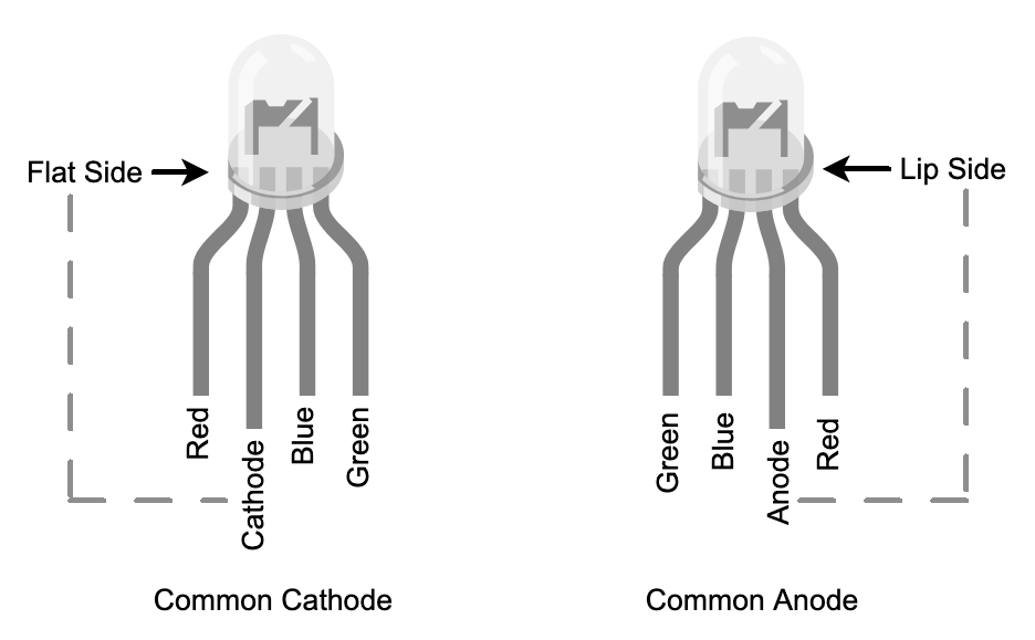
You will notice that two types are shown:
- Common Cathode: The red, green, and blue LEDs share a common cathode leg, meaning that the common leg is what connects to the negative or ground voltage source—cathode = negative.
- Common Anode: The red, green, and blue LEDs share a common anode leg, meaning that the common leg is what connects to the positive voltage source—anode = positive.
We learned previously in Chapter 5, Connecting Your Raspberry Pi to the Physical World, how to set the brightness of a single LED using PWM, but what happens if we vary the brightness of the three individual colors in an RGB LED? We mix the individual colors to create new colors! Let's create a circuit and start mixing.
Creating the RGB LED circuit
In this section, we will create a simple circuit to control an RGB LED, and we will be using a common cathode RGB LED (that is, the three individual LEDs share a common GND connection).
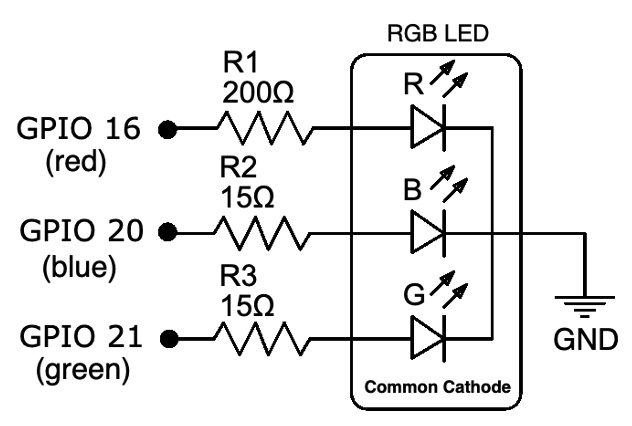
We will start by building the circuit as shown in Figure 8.2 on our breadboard:
Following is the accompanying breadboard layout for this schematic that we are about to build:

Here are the steps to follow, which match the numbered black circles in Figure 8.3:
- Start by placing the RGB LED into your breadboard, taking care to orientate the LED regarding the positioning of its cathode leg.
- Position the 200Ω resistor (R1). One end of this resistor connects to the red leg of the LED.
- Position the first 15Ω resistor (R2). One end of this resistor connects to the blue leg of the LED.
- Position the second 15Ω resistor (R3). One end of this resistor connects to the green leg of the LED.
- Connect a ground pin on your Raspberry Pi to the negative power rail.
- Connect GPIO 16 on your Raspberry Pi to the other end of the 200Ω resistor (R1) you placed at step 2.
- Connect the cathode leg of the RGB LED to the negative power rail.
- Connect GPIO 20 on your Raspberry Pi to the other end of the 15Ω resistor (R2) you placed at step 3.
- Connect GPIO 21 on your Raspberry Pi to the other end of the 15Ω resistor (R3) you placed at step 4.
Before we test our RGB LED circuit, let's briefly recap how we arrived at the 200Ω and 15Ω resistors in this circuit. The 200Ω resistor (R1) was derived using the same process we covered in Chapter 6, Electronics 101 for the Software Engineer. The 15Ω resistors for R2 and R3 are derived using the same process, with the difference being that the typical forward voltage used in the calculations for the blue and green LED was 3.2-volts. If you study the sample datasheet, you will notice that the forward voltage for the blue and green LEDs lists a maximum forward voltage of 4.0 volts. Even at the typical value of 3.2 volts, we are very close to the 3.3 volts of a Raspberry Pi GPIO pin. If you are unlucky to get an RGB LED needing more than 3.3 volts for its blue or green LED, it will not work—though I have never come across one...yet.
Now we are ready to test our RGB LED.
Running and exploring the RGB LED code
Now that you have your circuit ready, let's run our example code. Our example will light up the LED and make it alternate different colors. Here are the steps to follow:
- Run the code in the chapter08/rgbled_common_cathode.py file and you should observe the RGB LED cycling colors. Take note of the first three colors, which should be red, green, and then blue.
- If your first three colors are not red, green, and then blue, your RGB LED may have its legs in a different order than the RGB LED's pictured in Figure 8.1 and the circuit in Figure 8.2. What you will need to do is change the GPIO pin numbering in the code (see the following code snippets) and re-run the code until the color order is correct.
- After the red, green, and then blue cycle, the RGB LED will animate a rainbow of colors before the program completes.
Let's discuss the interesting sections of the code and see how it works:
In line (1), we are importing getrgb from the PIL.ImageColor module. getrgb provides us with a convenient way to convert common color names such as red or hex values such as #FF0000 into their RGB component values such as (255, 0, 0):
from time import sleep
import pigpio
from PIL.ImageColor import getrgb    # (1)

GPIO_RED = 16
GPIO_GREEN = 20
GPIO_BLUE = 21

pi.set_PWM_range(GPIO_RED, 255)      # (2)
pi.set_PWM_frequency(GPIO_RED, 8000)
# ... truncated ...
Starting at line (2), we explicitly configure PWM for each of the GPIO pins (the duty cycle range of 255 and frequency of 8,000 are the PiGPIO defaults). The PWM duty cycle range of 0 to 255 maps perfectly into the RGB component color value range of 0...255, which we will see shortly is how we set the individual brightness of each color LED.
In the following code, in line (3), we have the set_color() definition, which is responsible for setting the color of our RGB LED. The color parameter can be either a common color name such as yellow, a HEX value such as #FFFF00, or one of the many formats that getrgb() can parse (see the rgbled_common_cathode.py source file for a list of common formats):
def set_color(color):                                 # (3)
    rgb = getrgb(color)
    print("LED is {} ({})".format(color, rgb))
    pi.set_PWM_dutycycle(GPIO_RED,   rgb[0])          # (4)
    pi.set_PWM_dutycycle(GPIO_GREEN, rgb[1])
    pi.set_PWM_dutycycle(GPIO_BLUE,  rgb[2])
In line (4), we see how to use PWM with the individual GPIO pins to set the RBG LED's color. Continuing with yellow as our example, we see the following:
- GPIO_RED is set to a duty cycle of 0.
- GPIO_GREEN is set to a duty cycle of 255.
- GPIO_BLUE is set to a duty cycle of 255.
A duty cycle value for green and blue of 255 means that these LEDs are fully on and, as we know, mixing green and blue makes yellow.
As you browse the source file, you will encounter another two functions at lines (6) and (7):
def color_cycle(colors=("red", "green", "blue"), delay_secs=1):   # (6)
    # ...truncated...

def rainbow_example(loops=1, delay_secs=0.01):                    # (7)
    # ...truncated...
Both of these methods delegate to set_color(). color_cycle() loops through the list of colors provided as its color parameter, while rainbow_example() generates and loops through a range of colors to produce the rainbow sequence. These functions are what generated the light sequences when we ran the code in step 1.
Our RGB LED circuit comes with limitations and drawbacks:
- Firstly, we need three GPIO pins per RGB LED.
- Secondly, we're restricting the current to 8mA with the resistors so we cannot achieve maximum potential brightness of the individual LEDs (we would need ~20mA for full brightness).
While we could introduce transistors (or an appropriate multi-channel LED driver IC) to increase the current, our circuit would quickly become cumbersome! Luckily, there is another way we can create color with LEDs, and that is with addressable LEDs, which we'll look at next.
Controlling a multi-color APA102 LED strip with SPI
The APA102 is an addressable multi-color (RGB) LED that is controlled using a Serial Peripheral Interface (SPI). In simplistic terms, we send instructions to the LED asking it what color to display rather than individually controlling each of the three red-green-blue legs of the LED using PWM as we did in the previous example.
If you need a quick refresher on SPI, we covered it back in Chapter 5, Connecting Your Raspberry Pi to the Physical World. We will also discuss SPI further the context of the APA102, the Raspberry Pi, and Python after we explore APA102 specific code shortly.
APA102 LEDs can also be connected or chained together to create LED strips or LED matrices to create dynamic and multi-LED lighting and display solutions. Irrespective of how the LEDs are arranged, we control them using a common technique where we send multiple sets of instructions to a chain of APA102 LEDs. Each individual LED consumes one instruction and passes the rest on to be consumed by upstream LEDs. We will see this idea in action as we work with an APA102 LED strip shortly.
Let's create a circuit and run the code to control our APA102 LED strip.
Creating the APA102 circuit
In this section, we will create our APA102 circuit, as shown in the following diagram. We will do this on our breadboard in two parts:

Let's get started on the first part, which will be to place the components and wire up the low-voltage side of a logic level converter:

Here are the steps to follow. The step numbers match the numbered black circles in Figure 8.5:
- Place the logic level converter (logic level shifter) into the breadboard, positioning the low-voltage side toward your Raspberry Pi. Different logic level converters may have different labeling, however, it should be clear which is the low-voltage side. In our illustration, one side has an LV (Low Voltage) terminal while the other has an HV (High Voltage) terminal, which distinguishes the sides.
- Connect the negative rails on the left-hand side and right-hand side power rails.
- Connect a 3.3-volt pin on your Raspberry Pi to the positive rail of the left-hand side power rail.
- Connect the LV terminal on the logic level converter into the positive rail of the left-hand side power rail.
- Connect the MOSI (Master Out Slave In) pin on your Raspberry Pi to the A2 terminal on the logic level converter.
- Connect the SLCK (Serial Clock) pin on your Raspberry Pi to the A1 terminal on the logic level converter.
- Connect the GND terminal on the logic level converter to the negative rail on the left-hand side power rail.
- Connect the negative rail on the left-hand side power rail to a GND pin on your Raspberry Pi.
Now that we have wired the low-voltage side of the logic level converter to our Raspberry Pi, next we will wire the high-voltage side to the APA102 LED strip. As a reminder, Raspberry Pi GPIO pins operate at 3.3 volts (hence it's the low voltage) while the APA102 operates at 5 volts (hence it's the high voltage):
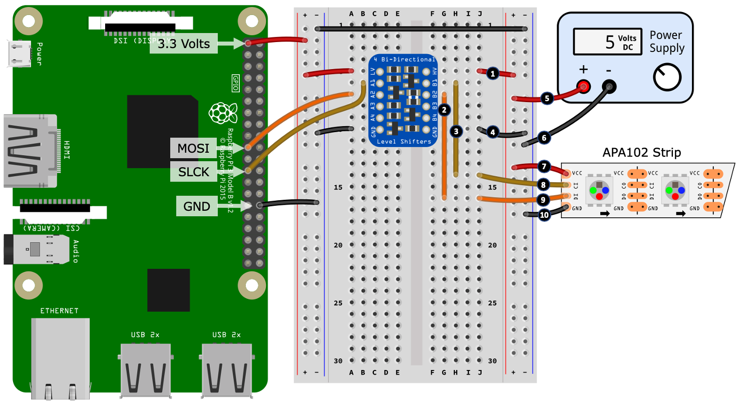
Here are the steps to follow for the second part of our build. The step numbers match the numbered black circles in Figure 8.6:
- Connect the HV terminal of the logic level converter to the positive rail of the right-hand side power rail.
- Place a jumper wire from terminal B2 to an unused row on your breadboard (in the illustration, this is shown at hole G16).
- Place another jumper wire from terminal B1 to an unused row on your breadboard (in the illustration, this is shown at hole H14).
- Connect the GND terminal on the high-voltage side of the logic level converter to the negative rail of the right-hand side power rail.
- Connect the positive output of your power supply to the positive rail of the right-hand side power rail.
- Connect the negative output of your power supply to the negative rail of the right-hand side power rail.
- Connect the VCC terminal or wire of your APA102 LED strip to the positive rail of the right-hand side power rail.
If your APA102 does not have the arrows, look at the naming of the terminals. One side of an LED strip may have CI/DI (I = Input), while the other side has DO/CO (O = Output). It's the Input side we need to connect to the logic level converter.
- Connect the CI (Clock Input) terminal or wire of your APA102 LED strip to the wire you placed at step 3 that connects back to the B1 terminal of the logic level converter.
- Connect the DI (Data Input) terminal or wire of your APA102 LED strip to the wire you placed at step 2 that connects back to the B2 terminal of the logic level converter.
- Finally, connect the GND terminal or wire of your APA102 LED strip to the negative rail of the right-hand side power rail.
Well done! You have now completed your APA102 LED strip circuit. As you completed this circuit build, you will have noticed that we are using a logic level converter. This is because the APA102 requires 5-volt logic to operate properly. The APA102 datasheet explicitly mentions the minimum logic voltage to be 0.7 VDD, which is 0.7 x 5 volts = 3.5 volts, which is higher than the Raspberry Pi's 3.3-volt logic-level.
Let's consider the situation (in case you were wondering) that 3.3 volts is only slightly less than 3.5 volts—surely, that's close enough? You can try and control an APA102 with 3.3-volts, and it may give you some level of success. However, you may also experience some random effects and confusion—for example, random LEDs not turning on or off as expected, flickering LEDs, or LEDs displaying with the wrong color. Unfortunately, the APA102 is one of the 5-volt logic devices that are not 3.3-volt compatible, so we must take the extra step and use a logic level converter to meet its 3.5-volt minimum logic-level requirements.
Now that you have built your APA102 circuit, next we will discuss the considerations we need to think about to power this circuit.
Powering the APA102 circuit
In Chapter 7, Turning Things On and Off, we discussed the importance of knowing the current requirements of a "load" that you are using. Let's apply that learning to our APA102 LED strip so we can power it correctly. Our example is assuming a LED strip containing 60 LEDs, however, you will need to adjust the calculations based on the number of LEDs on your strip.
By the way of example, we have the following:
- An APA102 LED strip with 60 LEDs.
- Each LED uses (on average) a maximum of 25mA (from the datasheet and confirmed by measurement).
- The LED strip consumes approximately 15mA when idle (no LED is lit).
Using the preceding values, we can calculate our expected maximum current requirement for 60 LEDs, which is just over 1.5 amps:

If we work in the assumption that we are using a breadboard power supply, then if we conservatively assume that our breadboard power suppler can only supply around 700mA maximum, we cannot realistically turn on all LEDs on a 60 LED strip to full white. If we do, then (depending on the power supply) it could turn off if its internal overload protection kicks in, it might go up in a puff of smoke, or it might limit its output current, which we may observe as the LEDs looking reddish rather than white.
Let's work backward to work out the safe number of LEDs that we can power from a 700mA power supply:

If we then subtract 2 LEDs (50mA) as a small safety buffer, we get 25 LEDs. Remember this number (or the number you calculate) as we will need it next when we run our example code.
After calculating the number of safe LEDs you can use with your power supply, we are now ready to configure and run our Python example.
Configuring and running the APA102 LED strip code
Now that you have your circuit ready and our LED strip's expected current usage, let's configure and light up our LED strip:
- Edit the chapter08/apa102_led_strip.py file and look for the following line near the top of the file. Adjust the number to be the number of safe LEDs you calculated previously, or the number of LEDs on your strip if it had a suitably capable power supply:
NUM_LEDS = 60 # (2)
- Save your edits and run the code. If everything is connected correctly, you should observe the LEDs on the strip cycle through the colors red, green, and blue and then perform a few different light sequences.
If your strip does not show red, green, and blue in that order, then you would need to adjust code to set the correct order—I'll show you where in the code you can adjust the LED ordering when we come to that section of code shortly.
With our safe number of LEDs now configured in code, let's walk through the code to see how it works.
APA102 LED strip code walkthrough
Starting at line (1) in the following code, we have the imports. We will be using a Python deque collection instance (I'll just refer to is as an array for simplicity) to model in-memory the APA102 LED strip—we will build up and manipulate the order of colors we want each individual LED on to display in this array before applying it to the LED strip. We then import the getrgb function from the PIL library for working with color formats (as we did in the preceding RGB LED example):
# ...truncated...
from collections import deque                                   # (1)
from PIL.ImageColor import getrgb
from luma.core.render import canvas
from luma.led_matrix.device import apa102
from luma.core.interface.serial import spi, bitbang
Lastly, the three luma imports are for the APA102 LED strip control. Luma is a mature high-level library for working with a range of common display devices using Python. It has support for LCDs, LED strips and matrices, and much more, including OLED displays, which we will cover later in this chapter.
We can only scratch the surface of what can be done with the Luma library in this chapter, so I encourage you to explore its documentation and range of examples—you'll find links in the Further reading section at the end of this chapter.
Next, we come to line (3) in the following code, where we assign color_buffer to an instance of deque that is initialized with the same number of elements as there are LEDs in our strip. Each element defaults to black (that is, the LED is off):
# ...truncated...
color_buffer = deque(['black']*NUM_LEDS, maxlen=NUM_LEDS)      # (3)
In line (4) in the following code, we start to create our software interface to the APA102. Here, we are creating a spi() instance representing the default hardware SPI0 interface on the Raspberry Pi. To use this interface, your APA102 must be connected to the SPI pins on your Raspberry Pi, which are as follows:
- DI connected to MOSI
- CI connected to SCLK
In the following code snippet port=0 and device=0 relate to the SPI0 interface:
# ...truncated...
serial = spi(port=0, device=0, bus_speed_hz=2000000)           # (4)
The bus_speed_hz parameter sets the speed of the SPI interface and, for our examples, we lower it from its default value of 8,000,000 to 2,000,000 just to ensure that your logic level converter will work. Not all logic level converters are the same, and they will have a maximum speed at which they can convert logic levels. If the SPI interface operates faster than the logic level converter can convert, our circuit will not work.
In line (5) in the following code—which is commented out—we have a software alternative to hardware SPI known as big-banging, which will work on any GPIO pins at the expense of speed. It's similar to the software versus hardware PWM trade-off we discussed back in Chapter 5, Connecting Your Raspberry Pi to the Physical World:
# ...truncated...
# serial = bitbang(SCLK=13, SDA=6)                             # (5)

# ...truncated...
device = apa102(serial_interface=serial, cascaded=NUM_LEDS)    # (6)
In line (6) in the preceding code, we created an instance of the apa102 class specifying the serial instance we just created, and the number of LEDs in our strip. From this point forward in code, to interact with our APA102 LED strip, we use the device instance.
To initialize our LED strip, in line (7) in the following code, we call device.clear() and set the default global contrast to 128 (so, half brightness). You can adjust this level to find a brightness that you are comfortable with, remembering that more contrast/brightness means more current usage. Note that previously when we calculated the number of safe LEDs, the 25mA per LED used in the calculations assumed maximum brightness (that is, 255):
device.clear()                                                   # (7)
contrast_level = 128 # 0 (off) to 255 (maximum brightness)
device.contrast(contrast_level)
In line (8) in the following code, we have the set_color() function. We use this function to set individual or all elements to a specified color in the color_buffer array. This is how we build up in-memory the color arrangements we want our APA102 LED strip to display:
def set_color(color='black', index=-1):                          # (8)
    if index == -1:
        global color_buffer
        color_buffer = deque([color]*NUM_LEDS, maxlen=NUM_LEDS)
    else:
        color_buffer[index] = color
Now, we will jump to line (12) in the following code block to the update() function. This function loops through color_buffer and, using the Luma device instance representing our APA102, it feeds the device the colors to display using draw.point((led_pos, 0), fill=color). This is the magic of the Luma library—it shields us from the lower level APA102 and SPI data and hardware protocols by giving us a very simple software interface to use.
It's important to remember that update() needs to be called after you make changes to color_buffer:
def update():                                                   # (12)
    with canvas(device) as draw:
        for led_pos in range(0, len(color_buffer)):
            color = color_buffer[led_pos]

            ## If your LED strip's colors are are not in the expected
            ## order, uncomment the following lines and adjust the indexes
            ## in the line color = (rgb[0], rgb[1], rgb[2])
            # rgb = getrgb(color)
            # color = (rgb[0], rgb[1], rgb[2])
            # if len(rgb) == 4:
            #     color += (rgb[3],)  # Add in Alpha

            draw.point((led_pos, 0), fill=color)
If, for some reason, you find your LED strip colors are not in the standard red, green, and blue order then the preceding commented-out section of code can be used to change the color order. I've never encountered a non-standard APA102, but I have read about addressable RGB LEDs having non-standard ordering, so I thought I'd just drop that bit of code in, just in case.
Moving on to lines (9), (10), and (11), we have three functions that simply manipulate color_buffer:
def push_color(color):                                       # (9)
    color_buffer.appendleft(color)

def set_pattern(colors=('green', 'blue', 'red')):           # (10)
    range(0, int(ceil(float(NUM_LEDS)/float(len(colors))))):
        for color in colors:
            push_color(color)

def rotate_colors(count=1):                                 # (11)
    color_buffer.rotate(count)
push_color(color) in line (9) pushes a new color into color_buffer at index 0 while set_pattern() in line (10) fills color_buffer with a repeating color pattern sequence. rotate_colors() in line (11) rotates the colors in color_buffer (and wraps them around—the last one becomes for the first one). You can rotate backward by using a count value < 0.
Finally, toward the end of the source code, we have the following functions that provide the examples you saw when you run the file. These functions use combinations of the functions discussed previously to control the LED strip:
- cycle_colors(colors=("red", "green", "blue"), delay_secs=1)
- pattern_example()
- rotate_example(colors=("red", "green", "blue"), rounds=2, delay_secs=0.02)
- rainbow_example(rounds=1, delay_secs=0.01)
We will complete our coverage of the APA102 with a few concluding notes on its use of the SPI interface.
Discussion of APA102 and the SPI interface
If you cast your mind back to Chapter 5, Connecting Your Raspberry Pi to the Physical World, where we discussed Serial Peripheral Interface (SPI), you may remember that we mentioned it uses four wires for data transfer. However, if you consider our circuit in Figure 8.6, we're only using two wires (DI and CI), not four. What's going on?
Here is the SPI mapping for the APA102:
- Master-Out-Slave-In (MOSI) on your Raspberry Pi connects to Data In (DI) on the APA102. Here, your Raspberry Pi is the master sending data to the slave APA102 LEDs on the strip.
- Master-In-Slave-Out (MISO) is not connected because the APA102 does not need to send data back to the Raspberry Pi.
- SCLK on your Raspberry Pi connect to the Clock In (CI) on the APA102.
- Client Enable/Slave Select (CE/SS) is not connected.
The last line CE/SS of importance and worthy of further discussion. A CE/SS channel is used by a master device to tell a specific slave device that it's about to receive data. It's this mechanism that allows a single SPI master to control multiple SPI slaves.
But, we're not (and cannot) use CE/SS it with the APA102 because we have nowhere to connect the CE/SS pins to. The implication of this is that the APA102 is always listing for instructions from a master, effectively hogging the SPI channel.
If we are using an APA102 (or any device that has no CE/SS), then we cannot connect more than one SPI device to a master's hardware SPI, unless we take extra steps. Some of the options are as follows:
- Use big-banging on generic GPIO pins if the performance reduction does not have adverse effects.
- Enable hardware SPI1 on your Raspberry Pi. It's not enabled by default and requires editing /boot/config.txt. You'll find instructions and tips if you search the web for Raspberry Pi enable SPI1.
- Find a logic level converter that includes an enable pin and write code to manually control this pin as a proxy CE/SS.
We will conclude this section on the APA102 with a few troubleshooting tips.
APA102 LED strip troubleshooting tips
If you cannot get your APA102 to light up or if you find that random LEDs are not turning on or off or they are displaying unexpected colors or random flickers, try the following:
- The APA102 needs 5-volt logic: Make sure you are using a logic level converter and that is connected the correct way around—HV to 5 volts and LV to 3.3 volts.
- Ensure that the DI/CI side of the APA102 is connected to the logic level converter.
- Make sure your power source can supply enough current. As an example, under-supply of current or voltage can make white look more like red.
- Make sure the ground of your power supply is connected to a ground pin on your Raspberry Pi.
- If you are using big banging, move to hardware SPI.
- If using the hardware SPI (that is, creating an instance of the spi() class), try the following:
- If you are receiving the error SPI device not found, make sure SPI has been enabled in the Raspbian OS. We covered this in Chapter 1, Setting Up Your Development Environment.
- If you have been using GPIO 8,9, 10, or 11 previously for general I/O, then either disable and re-enable the SPI interface as per the preceding point or reboot your Raspberry Pi to reset the hardware SPI interface.
- Try lowering the SPI bus speed in case your logic level converter cannot keep up—that is, it cannot convert 3.3-volt to 5-volt signals as fast as the SPI interface is producing them (hint: lower the bus_speed_hz parameter in serial = spi(port=0, device=0, bus_speed_hz=2000000) to 1,000,000 or 500,000).
- Connect the APA102's DI and CI directly to SDA and SCLK on the Raspberry Pi. The goal here is to bypass the logic level converter to rule it out as the problem.
Well done! This was a lengthy and detailed section on the APA102. We covered a lot of concepts in addition to the APA102 itself, including how to calculate the power requirements of a LED strip and an introduction to the Luma library, which can be used to control a host of different lighting and display devices besides the APA102. Then, we concluded with practical troubleshooting tips in case your APA102 circuit, setup, or code did not work on the first go.
All of this knowledge and experience will be adaptable to similar lighting projects you undertake and SPI-based projects in general. In particular, it will be a helpful reference to calculate the power requirements of lighting projects and troubleshoot circuits and code when they do not work. It also provides the basic foundations that we will be building on in the next section where we look at how to interface an OLED display with our Raspberry Pi.
Using an OLED display
An OLED or Organic LED display is a type of technology used to make screens. Our example will be using an SSD1306, which is a monochrome 128x64 pixel display, however, the information will apply to other OLED displays too.
Our sample program will read your Raspberry Pi's CPU temperature and display it on the OLED display together with a thermometer icon. We will be assuming the OLED will connect using an I2C interface, however, an SPI interface device should also be compatible if you use an spi() instance (like in the APA102 example) for the serial object. The ability to change the interacting method used by the Luma library means you can reuse existing code with compatible display devices with minimal code changes.
We will commence by connecting the OLED display to the Raspberry Pi and verifying that it is connected.
Connecting the OLED display
Let's connect your OLED display to your Raspberry Pi, as shown in Figure 8.7:
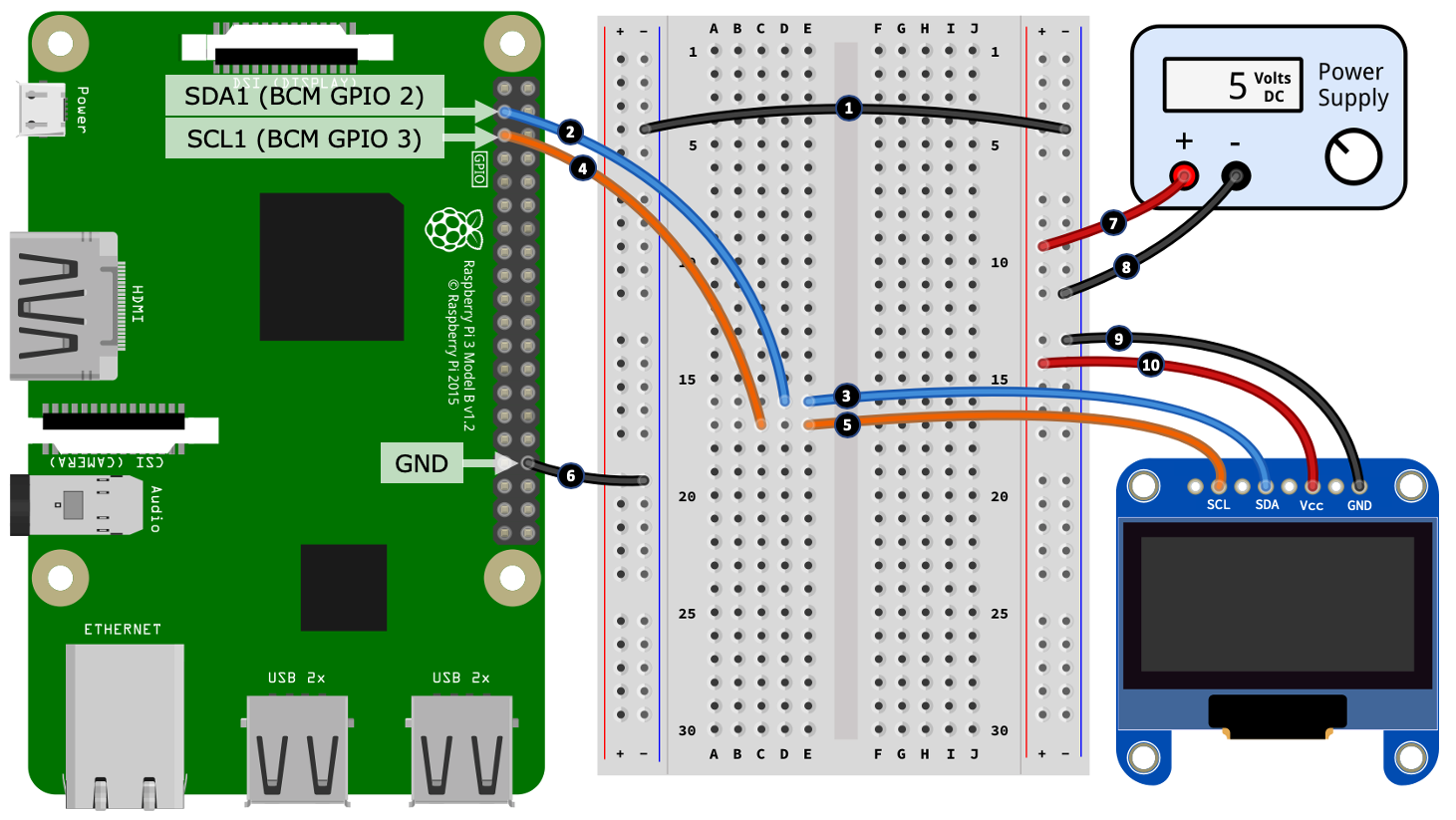
You can connect the OLED with the following steps, which correspond to the numbered black circles in Figure 8.7:
- Connect the negative rails on the left-hand side and right-hand side power rails.
- Connect the SDA1 (Data) pin of your Raspberry Pi into a vacant row on your breadboard.
- Connect the SDA (Data) terminal or wire of your OLED display into the same row use used for step 2.
- Connect the SCL1 (Clock) pin of your Raspberry Pi into a vacant row on your breadboard.
- Connect the SCL (Clock) terminal or wire of your OLED display into the same row use used for step 4.
- Connect a GND Pin on your Raspberry Pi to the negative rail of the left-hand side power rail.
- Connect the positive output of a 5-volt power supply to the positive rail of the right-hand side power rail.
- Connect the negative output of a 5-volt power supply to the negative rail of the right-hand side power rail.
- Connect the GND terminal or wire of your OLED display to the negative rail of the right-hand side power rail.
- Connect the VCC terminal or wire of your OLED display (it might also be named VDD, Vin, V+, or something similar indicating a voltage input) to the positive rail of the right-hand side power rail.
Good job! This completes our OLED circuit. As you can see, we are powering the OLED from a 5-volt power supply, however, the SDA (Data)/SLC (Clock) channels are connected directly to your Raspberry Pi. Unlike the APA102 LED strip we used in the previous section, the SSD1306 OLED is 3.3-volt logic compatible, hence, we do not need a logic level converter to convert logic level voltages on the clock and data channels.
Let's briefly consider the current requirements for the SSD1306 OLED. My testing resulted in the following current measurements:
- Black screen: ~3mA
- White screen (every pixel on): ~27mA
At a maximum current usage of ~27mA, you can try connecting the +5V to the Raspberry Pi's 5-volt pin, but remember this will take reserve current away from your Raspberry Pi (and it may reset when you run the code if your Raspberry Pi's power supply is not adequate).
With your OLED connected to your Raspberry Pi's SDA and SCL pins next, we will verify that it has been detected by your Raspberry Pi using the i2cdetect utility.
Verifying whether the OLED display is connected
Previously, in Chapter 5, Connecting Your Raspberry Pi to the Physical World, we used the i2cdetect command-line tool to check whether an I2C device was connected and to verify its I2C address. Check that your Raspberry Pi can see your OLED display by running the following in a Terminal:
$ i2cdetect -y 1
If your OLED is connected, you will see the following output, which tells us that the OLED was detected and has the hex address, 0x3C:
# ...truncated...
30: -- -- -- -- -- -- -- -- -- -- -- -- 3c -- -- --
# ...truncated...
If your address is different, that's okay, we just need to adjust the address in code which we will do next.
Configuring and running the OLED example
The code we are about to explore is contained in the chapter08/oled_cpu_temp.py file. Please review this file to get an overall view of what it contains before continuing:
- If the OLED I2C address you obtained in the preceding was different to 0x3C, find the following line in the source code and update the address parameter to match your OLED I2C address:
serial = i2c(port=1, address=0x3C)
- Run the program, and you should observe the CPU temperature and a thermometer icon drawn on the OLED display.
Once you have configured your OLED display address in code and confirmed the example works on your OLED, we are ready to review the code and learn how it works.
OLED code walkthrough
Commencing with the imports, in line (1), we import classes from the PIL (Pillow) module, which we use to create the image we want to render on the OLED display. We also import several other classes from the Luma module related to our SSD1306 OLED and its I2C interface (SPI is also imported for reference).
We see how to create an I2C instance in line (2) representing the interface that our OLED is connected to. Commented out is an SPI alternative. In line (3), we create an instance of ssd1306 that represents our OLED display and assign it to the device variable. If you are using a different OLED display than the SSD1306, you will need to identify and adjust the ssd1306 import line, and the device instance created in line (3):
from PIL import Image, ImageDraw, ImageFont         # (1)
from luma.core.interface.serial import i2c, spi
from luma.core.render import canvas
from luma.oled.device import ssd1306
#...truncated...

# OLED display is using I2C at address 0x3C
serial = i2c(port=1, address=0x3C)                  # (2)
#serial = spi(port=0, device=0)

device = ssd1306(serial)                            # (3)
device.clear()
print("Screen Dimensions (WxH):", device.size)
In line (4), we encounter the get_cpu_temp() function, which calls a command-line utility to retrieve your Raspberry Pi's CPU temperature before parsing and returning the result that we will use shortly to construct our display image:
def get_cpu_temp():     # (4)
    temp = os.popen("vcgencmd measure_temp").readline() # Eg 62.5'C
    data = temp.strip().upper().replace("TEMP=", "").split("'")
    data[0] = float(data[0])

    if data[1] == 'F':  # To Celsius just in case it ever returns Fahrenheit
        data[0] = (data[0] - 32) * 5/9
        data[1] = 'C'

    return (data[0], data[1])  # Eg (62.5, 'C')
In the following code in line (5), we define temperature thresholds that influence the icon we show on our OLED display. We will also use the high threshold to make the OLED display blink to help to create a visual attention-grabber.
In line (6), we load in three thermometer images and scale them down starting at line (7) to a size that is workable with the 128x64 pixel dimensions of our SSD1306 OLED:
# Temperature thresholds used to switch thermometer icons
temp_low_threshold = 60   # degrees Celsius                     # (5)
temp_high_threshold = 85  # degrees Celsius

# Thermometer icons
image_high = Image.open("temp_high.png")                        # (6)
image_med  = Image.open("temp_med.png")
image_low  = Image.open("temp_low.png")

# Scale thermometer icons (WxH)
aspect_ratio = image_low.size[0] / image_low.size[1]            # (7)
height = 50
width = int(height * aspect_ratio)
image_high = image_high.resize((width, height))
image_med  = image_med.resize((width, height))
image_low  = image_low.resize((width, height))
Next, we define two variables starting at line (8) in the following. refresh_secs is the rate at which we check the CPU temperature and update the OLED display while high_alert is used to flag a breach of the maximum temperature threshold and start the screen blinking:
refresh_secs = 0.5   # Display refresh rate                           #(8)
high_alert = False # Used for screen blinking when high temperature

try:
    while True:
        current_temp = get_cpu_temp()
        temp_image = None

        canvas = Image.new("RGB", device.size, "black")              # (9)
        draw = ImageDraw.Draw(canvas)                                # (10)
        draw.rectangle(((0,0),
                   (device.size[0]-1, device.size[1]-1)),
                   outline="white")
In the while loop, in line (9), we see the use of the PIL module. Here, we are creating a blank image using the same dimensions as the OLED device (that is, 128x64 for the SSD1306) and storing it in the canvas variable. In subsequent code, we manipulate this in-memory canvas image before sending it to the SSD1306 for rendering.
The draw instance created in line (10) is a PIL helper class that we use for drawing on the canvas. We use this instance for placing a bounding rectangle around the canvas and will use it later to add text to the canvas. The draw instance can also be used to draw many other shapes including lines, arcs, and circles. A link to the PIL API documentation can be found in the Further reading section.
The block of code starting at line (11) in the following is what will make our OLED display blink when high_alert is True:
        if high_alert:                                     # (11)
            device.display(canvas.convert(device.mode))
            high_alert = False
            sleep(refresh_secs)
            continue
Starting at line (12), we compare the temperature reading we obtained from get_cpu_temp() to the threshold values defined earlier. Depending on the result, we change the thermometer image that will be shown, and for a high threshold breach, we set high_alert = True. Setting high_alert to True will cause the OLED display to blink on the next loop iteration:
        if current_temp[0] < temp_low_threshold:           # (12)
            temp_image = image_low
            high_alert = False

        elif current_temp[0] > temp_high_threshold:
            temp_image = image_high
            high_alert = True

        else:
            temp_image = image_med
            high_alert = False
We start constructing our display starting at line (13) in the following. We calculate image_xy to be a point at which our thermometer image would be centered on the display and then offset that point using the image_x_offset and image_x_offset variables to move the image into the position we want it rendered.
In line (14), we then paste our thermometer image onto the canvas:
# Temperature Icon
image_x_offset = -40                    # (13)
image_y_offset = +7
image_xy = (((device.width - temp_image.size[0]) // 2) +
        image_x_offset, ((device.height - temp_image.size[1]) // 2)
        + image_y_offset)
canvas.paste(temp_image, image_xy)      # (14)
Moving on to line (15) in the following code block, we create the text we want to display on our OLED screen and use the same technique as for the image to position the text on the canvas in line (17). Notice the use of draw.textsize() to obtain the pixel dimensions of the text.
In line (16), we set font = None to use a default system font for the example because I cannot be entirely sure what fonts you have available on your Raspberry Pi. The line after line (16) that is commented out shows an example of using a custom font.
Finally, in line (18), we draw the text on the canvas:
# Temperature Text (u00b0 is a 'degree' symbol)                 # (15)
text = "{}u00b0{}".format(current_temp[0], current_temp[1]) # Eg 43'C

font = None # Use a default font.                                # (16)
# font = ImageFont.truetype(font="Lato-Semibold.ttf", size=20)

text_size = draw.textsize(text, font=font)                       # (17)
text_x_offset = +15
text_y_offset = 0
text_xy = (((device.width - text_size[0]) // 2) + text_x_offset,
((device.height -  text_size[1]) // 2) + text_y_offset)
draw.text(text_xy, text, fill="white", font=font)                # (18)
We have now reached the tail-end of the while loop. In line (19) in the following code, we use the device instance that represents the SSD1306 OLED display to display canvas. The canvas.convert(device.mode) call converts the canvas image that we created into a format usable by the SSD1306:
# Render display with canvas
device.display(canvas.convert(device.mode))        # (19)
sleep(refresh_secs)
Before we complete our exploration of OLEDs, I want to point you to more examples. The Luma library contains an extensive range of examples covering many aspects of using an OLED display. A link to the examples can be found in Further reading.
OLED displays are low cost, small in size, and light on power consumption, so you frequently find them used in battery-operated devices. If you want to explore other display options for your Raspberry Pi, you might like to investigate the range of Raspberry Pi TFT displays that are available (just search for that term on sites such as eBay.com or Banggood.com). These are full-color mini-monitors for your Raspberry Pi, and there are even touch-screen options available.
This now concludes our coverage of lighting and displays with our Raspberry Pi and Python. The knowledge you have learned so far will enable you to use and correctly power your own simple LED lighting projects and leverage a range of OLED displays for those projects where you wish to display textual and graphical information to users.
To conclude the exercises for this chapter, next, we will revisit Pulse-Width-Modulation (PWM) briefly and see how we can use it to generate sound.
Making sound with buzzers and PWM
In the final section of this chapter, we will walk through an example of how to make simple sound and music with PWM. Our sample program is going to play a musical scale on the buzzer, and we will be using a music score format called Ring Tone Text Transfer Language (RTTTL), which was developed by Nokia in the pre-smartphone era for creating ringtones. As we learn, we can use a simple Python library to parse an RTTTL music score and turn its notes into a PWM frequency and duration that can then be used to associate a buzzer to create an auditable tune.
To make a sound with PWM, we need a form of a speaker, and we will be using what is known as a passive buzzer. Buzzers come in two basic forms:
- Active buzzers: These buzzers contain an internal oscillator that generates a single set tone. All you need to do us apply a DC voltage to an active buzzer and it will make a noise.
- Passive buzzers: These do not contain any internal smarts to make them work, so the oscillating must be done by the controlling device. The upside of this is that we can set and change the tone as we wish, and we can achieve this using PWM.
Now that we understand a little about how to make sound with buzzers, let's continue and create our sound-making circuit.
Building the RTTTL circuit
In this section, we will be building a circuit to drive a passive buzzer. This circuit, shown in Figure 8.8 is very similar to the MOSFET circuit that we covered in Chapter 7, Turning Things On and Off, only this time with a buzzer connected as the load:

We will start our circuit build by placing the components onto our breadboard:

The following step numbers match the numbered black circles in Figure 8.9:
- Place the MOSFET onto the breadboard, paying attention to the orientation of the component with regards to the legs. Please see Figure 7.7 in Chapter 7, Turning Things On and Off, if you need help to identify the MOSFET's legs.
- Place the 100kΩ resistor (R2) into your breadboard. One end of this resistor shares the same row as the MOSFET's Gate (G) leg.
- Place the 1kΩ resistor (R1) into your breadboard. One end of this resistor also shares the same row as the MOSFET's Gate (G) leg.
- Place the diode into your breadboard, with the cathode leg (the leg at the end with the band) pointing toward the end of the breadboard.
- Connect the positive wire of your buzzer into the same row shared by the diode's cathode leg.
- Connect the negative wire of your buzzer into a vacant breadboard row.
Now that we have laid the components, let's wire them up:

The following step numbers match the numbered black circles in Figure 8.10:
- Connect the negative rail of the left-hand side power rail to the 1kΩ resistor (R2).
- Connect the Source leg (S) of the MOSFET to the negative rail of the left-hand side power rail.
- Connect the negative rail of the left-hand side power rail to a GND pin on your Raspberry Pi.
- Connect the end of the 100kΩ resistor (R1) to GPIO 12/PWM0 on your Raspberry Pi. As a reminder, GPIO 12 in its alternative function is channel PWM0, a hardware PWM pin.
- Connect the Drain leg (D) of the MOSFET to the anode leg of the diode.
- Connect the anode leg of the diode to the negative wire of your buzzer.
- Connect the buzzer's positive wire/diode's cathode leg into the positive rail of the right-hand side power rail.
- Connect the negative rails of the left-hand side and right-hand side power rails.
- Connect the positive output of the power supply to the positive rail of the right-hand side power rail.
- Connect the negative output of the power supply to the negative rail of the right-hand side power rail.
Now that you have completed this circuit build, we will proceed and run our Python example, which will make some music!
Running the RTTTL music example
Run the code in the chapter08/passive_buzzer_rtttl.py file, and your buzzer will play a simple musical scale.
The code to perform this is quite simple. In line (1) in the following code, we are using the rtttl module to parse an RTTTL music score into a series of notes defined by frequency and duration. Our score is stored in the rtttl_score variable:
from rtttl import parse_rtttl
rtttl_score = parse_rtttl("Scale:d=4,o=4,b=125:8a,8b,        # (1)
    8c#,8d,8e,8f#,8g#,8f#,8e,8d,8c#,8b,8a")
Next, in line (2), we loop through the parsed notes in rtttl_score and extract the frequency and duration:
    for note in rtttl_score['notes']:                        # (2)
        frequency = int(note['frequency'])
        duration = note['duration'] # Milliseconds
        pi.hardware_PWM(BUZZER_GPIO, frequency, duty_cycle)  # (3)
        sleep(duration/1000)                                 # (4)
In line (3), we set the frequency on the buzzer's GPIO pin using PWM, and hold the note for its duration at line (4) before continuing to the next note.
Making music with RTTTL is very electronic-sounding, so to speak, and is a popular technique with resource-limited microcontrollers. However, remember that, with our Raspberry Pi, we have more than enough resources and the built-in hardware to play rich media such as MP3s.
If you want to explore playing and controlling MP3s via Python, you'll find many resources, tutorials, and examples across the web. Unfortunately, there are many ways to achieve this task (including changes across different versions of Raspbian OS), so it can be a bit finicky at times getting your Raspberry Pi and Raspbian OS set up and configured reliably. If you go down this route, my recommendation is to explore playing MP3s and controlling audio (that is, changing volume) on the command line first. Once you have a stable and reliable setup, then proceed to explore a Python-based way.
Summary
In this chapter, we learned how to use PWM to set the color of an RGB LED and that a standalone single RGB LED requires three dedicated GPIO pins to work—one for each of the colors, red, green, and blue. We then explored another type of RGB LED, the APA102, which is a 2-wire SPI controllable device that can be chained together to create LED lighting strips. Next, we learned how to use an OLED display by creating an example application that displayed your Raspberry Pi's CPU temperature. We concluded with an example of using PWM together with a passive buzzer to make sound by parsing an RTTTL music score.
What you have learned in this chapter will allow you to add visual and auditable feedback to your own projects. You will also be able to extend your learning to other types of displays with relative ease, as the Luma library we have used is capable of working with a range of other display types and models in addition to the APA102 LED strip and SSD1306 OLED devices we used in this chapter.
In the next chapter, we will be looking at components and techniques to measure environmental conditions including temperature, humidity, and light.
Questions
As we conclude, here is a list of questions for you to test your knowledge regarding this chapter's material. You will find the answers in the Assessments section of the book:
- Your APA102 LED strip is set to show all LEDs as white, but instead, all of the LEDs look reddish. What could be the problem?
- What limitation does the APA102 place on SPI?
- Your APA102 does not work when you use a logic level converter but appears to work when you connect it directly to the MOSI and SCK pins on your Raspberry Pi (hence bypassing the logic level converter). What are some possible causes of the problem?
- What is the basic process for creating and displaying an image on an OLED display using the Luma OLED library?
- What is RTTTL?
Further reading
An APA102 is a good choice to commence your learning on lower level data protocol and communication. After reviewing the APA102 datasheet for its data protocol (see the link under Technical requirements at the start of this chapter), the next logical step is to review some lower-level code. The APA102 example for PiGPIO is a one such starting point, but you'll find others on PyPi.org:
The Luma suite of libraries offers many high-level modules for integrating common display with a Raspberry Pi beyond the APA102 and SSD1306 OLED we covered in this chapter. Furthermore, Luma contains an extensive range of examples:
- Luma: https://pypi.org/project/luma.core (follow the links for different display types)
- Luma examples on GitHub: https://github.com/rm-hull/luma.examples
Luma uses a PIL (Python Imaging Library)/Pillow comparable API for drawing and manipulating displays. We specifically used ImageDraw in our OLED example. You will find the PIL API documentation at the following link:
If you would like to explore the RTTTL format further, its Wikipedia site is an excellent starting point: