
So far in this book, we've focused mostly on software. In this chapter, we're about to flip that and focus on electronics. We'll do this by learning about the fundamental electronic concepts that are the basis for interfacing basic electronic sensors and actuators with your Raspberry Pi. What we'll learn about in this chapter will provide the foundation for many of the circuits we'll discuss in Section 3, IoT Playground.
We will begin by covering the essential workshop tools that you will require for working with electronics, and provide practical tips to help you purchase electronic components. Next, we'll provide you with guidelines to help keep your Raspberry Pi from being damaged as you work with its physical GPIO pins. We will also discuss common ways electronic components fail to help you diagnose circuits that do not work.
We will then get into the electronics! Here, we will look at two important electronic laws – Ohm's Law and Kirchoff's Law – and work through a practical example to explain why we used a 200Ω resistor to accompany our LED in the circuits we were using in earlier chapters (if you need a refresher about this LED circuit, please see Chapter 2, Getting Started with Python and IoT).
Next, we will explore both digital and analog electronics and discuss the core circuits and ideas that are used to integrate them with your Raspberry Pi. We will finish this chapter by learning about logic-level conversion, a practical technique that is used to interface electronics that operate at different voltages.
The following topics will be covered in this chapter:
- Fitting out your workshop
- Keeping your Raspberry Pi safe
- Three ways electronic components fail
- Electronic interfacing principles for GPIO control
- Exploring digital electronics
- Exploring analog electronics
- Understanding logic-level conversion
Technical requirements
To perform the exercises in this chapter, you will need the following:
- Raspberry Pi 4 Model B
- Raspbian OS Buster (with a desktop and recommended software)
- Minimum Python version 3.5
These requirements are what the code examples in this book are based on. The code examples should work without the need to modify a Raspberry Pi 3 Model B or use a different version of Raspbian OS, as long as your Python version is 3.5 or higher.
You can find this chapter's source code in the chapter06 folder in this book's GitHub repository: https://github.com/PacktPublishing/Practical-Python-Programming-for-IoT.
You will need to execute the following commands in a Terminal to set up a virtual environment and install the Python libraries required for this chapter:
$ cd chapter06              # Change into this chapter's folder
$ python3 -m venv venv      # Create Python Virtual Environment
$ source venv/bin/activate  # Activate Python Virtual Environment
(venv) $ pip install pip --upgrade        # Upgrade pip
(venv) $ pip install -r requirements.txt  # Install dependent packages
The following dependency is installed from requirements.txt:
- PiGPIO: The PiGPIO GPIO library (https://pypi.org/project/pigpio)
The hardware components we will require for this chapter are as follows:
- A digital multimeter.
- A red LED (datasheet for reference – https://www.alldatasheet.com/datasheet-pdf/pdf/41462/SANYO/SLP-9131C-81.html; click on the PDF option).
- Momentary Push Button Switch (SPST).
- 200 Ω, 1k Ω, 2k Ω, and 51k Ω resistors.
- 10k Ω potentiometer
- 4-channel MOSFET-based logic level shifter/converter module. See Figure 6.12 (left-hand side module) for an example.
Fitting out your workshop
Having the right tools and equipment is important to help you put together, build, test, and diagnose problems in electronic circuits. Here are the bare essentials (besides electronic components) you're going to need as you journey deeper into electronics and create circuits like the ones shown in this book:
- Soldering iron: You will need a soldering iron (and solder) for odd jobs such as joining header pins to breakout boards or soldering wires to components so that they can be plugged into your breadboard.
- Solder: Look for a general-purpose 60/40 (60% tin and 40% lead) resin core solder with a diameter of around 0.5 mm to 0.7 mm.
- Solder Sucker/Vacuum: We all make mistakes, so this device helps you remove solder from a joint and undo your soldering work.
- Wet Sponge or Rag: Always keep your soldering iron tip clean by removing built-up solder – a clean tip promotes clean soldering.
- Wire Stripper and Cutters: Keep a set of wire cutters and strippers just for your electronics work. Chips and burrs in the cutter blades from other uses will degrade their performance.
- Digital Multi Meter (DMM): An entry-level DMM will be suitable for general work and will include a range of standard features such as voltage, current, and resistance measurements.
- Breadboard: I highly recommend purchasing two full-size breadboards and joining them together to get more breadboard real-estate. It'll make working with the breadboard and components much easier.
- Dupont (Jumper) Cables: These are the wires used with a breadboard. They come in various types: male-male, male-female, and female-female. You will need a mixture of them all.
- Loose Header Pins: These are useful for joining Dupont cables together and for making non-breadboard-friendly components breadboard-friendly.
- External Power Supply: This is so you can power circuits externally from your Raspberry Pi. For the purposes of this book, at a minimum, you will need a breadboard power supply that can supply 3.3 and 5 volts.
- Raspberry Pi Case: Make sure you have a case for your Raspberry Pi. A caseless Raspberry Pi with all those exposed electronics underneath is an accident waiting to happen.
- GPIO Breakout Header: This makes working with a Raspberry Pi and breadboards much easier.
This list shows the basic tools that we require, but what about the actual electronics and gadgets to play with? We'll look at that next.
Buying electronic modules and components
A catalogue of all the components and modules used throughout this book is contained in the Appendix. In this section, I want to provide a few general tips and guidelines to help you out when purchasing electronic components in case you have not done much of this before. We will start with a few tips to help you when purchasing loose components.
Purchasing lose components
When it comes to purchasing loose components such as resistors, LEDs, push buttons, transistors, diodes, and other components (which we will be exploring in Section 3, IoT Playground – Practical Examples to Interact with the Physical World, of this book), there are some guidelines that will help you out, as follows:
- Source the specific component values and part numbers listed in the Appendix. Purchase many spares since it's possible that you will damage components while learning to use them.
- If you're purchasing from sites such as eBay or Banggood, carefully review the details of the item, and preferably zoom in on the images of the parts and check the part numbers shown. Never rely solely on the title of the listing. Many sellers add a variety of terms to their titles for search optimization purposes that do not necessarily relate to the actual item being sold.
- Search around sites such as eBay and Banggood for terms such as electronic starter kit. You may be able to pick up a mixed bundle of loose components in one transaction.
These points also apply when purchasing sensors and modules, which we will talk about next.
Purchasing open source hardware modules
I'm sure you are aware of open source software, but there is also open source hardware. This is where the maker of some electronic hardware publishes the design and schematics publicly so that anyone can make (and sell) the hardware. You will find many breakout modules (such as the ADS1115 modules we used in Chapter 5, Connecting Your Raspberry Pi to the Physical World) from various vendors with different (or no) branding. Different vendors may also make their modules in different colors and, while less common, different physical layouts.
The core or heart of a module – particularly the more simple ones – is often a single integrated circuit (IC or chip). As long as the core IC and I/O pins are similar, it's generally safe to assume that boards will operate the same way.
SparkFun (https://www.sparkfun.com/) and Adafruit (http://adafruit.com/) are two companies producing open source hardware that many others clone. A big advantage you will get when you purchase from these companies is that, often, their products include code examples, tutorials, and tips on using their products, and the products are of good quality. Yes, you may pay a little more, but when starting out and especially for more complex electronics, the investment can save you a lot of time. It's not uncommon to find that cheaper clones arrive faulty – so you'll need to purchase two or more to hedge your bets.
We have now covered some suggestions and tips to help you fit out your workshop and buy electronic components. Having the right tools available and learning how to use them (especially soldering, which will take practice if this is a new skill) is essential to help make your electronics journey a smooth and productive one. At times, purchasing loose components can be confusing and sometimes error-prone, especially where subtle differences in specifications or labeling can have dramatic practical implications, so be diligent and double-check what you are buying if you are unsure. Finally, as suggested in the Appendex, purchase spare components. It's no fun having to abruptly stop your learning midway through a circuit build because a component gets damaged and you need to source or wait for a replacement to arrive!
Next, we will discuss guidelines to help you keep your Raspberry Pi safe when interfacing electronics to it.
Keeping your Raspberry Pi safe
In this section, we will cover guidelines and suggestions to help keep your Raspberry Pi safe while you are interfacing electronics with it. By being careful and diligent in your approach, these guidelines will help you minimize any potential for damage to your Raspberry Pi or electronics components.
Don't worry if some of the electronic-orientated points such as voltages and currents do not make sense at the moment. We'll be touching on these concepts throughout this chapter, and during Section 3, IoT Playground – Practical Examples to Interact with the Physical World, of this book, so more context will be coming:
- Never apply more than 3.3 volts to any input GPIO pin. Higher voltages can cause damage.
- Never use more than 8 mA from any single output GPIO pin (they can handle up to ~16 mA, but by default, stick to 8 mA to ensure reliable GPIO operation). As a rule of thumb, do not power anything other than LEDs and breakout modules unless you know what you are doing. In Chapter 7, Turning Things On and Off, we'll look at circuits that can be used to switch higher current and voltage loads.
- Never use more than a combined 50 mA across multiple GPIO pins.
- Never use more than 0.5 mA with a GPIO pin configured for input.
- Always disconnect the power to your circuits before connecting or disconnecting them to your Raspberry Pi or making any changes.
- Always stop any running programs that are interacting with GPIO pins before connecting, disconnecting, or working on a circuit.
- Always double-check your wiring before applying power to your circuits.
- Never substitute random component values in a circuit – they don't have the correct and expected value shown in the schematic diagram.
- If you see a lightning bolt icon on your Raspberry Pi's monitor or the monitor goes blank when you run your program, that's the Pi telling you that your circuit is drawing too much power from the Raspberry Pi.
- Never directly connect and use inductive loads and mechanical devices such as motors, relays, or solenoids that use magnates from GPIO pins. They can draw too much current and cause a phenomenon known as EMF flyback, which can damage surrounding electronics, including your Raspberry Pi.
When working with electronics, from time to time, components do get damaged or fail. Let's briefly look at ways this can occur.
Three ways electronic components fail
Working with electronics is different from software. In the software world, we can change code, break code, debug code, and fix code as many times as we want with no real harm. We can also freely back up and restore states and data. When working with electronics, we do not have this luxury. We're in the physical world, and if something gets damaged, it's final!
Components and circuits made of components, including a Raspberry Pi, can become damaged and fail in many different ways due to them being connected incorrectly, oversupplying too much voltage, supplying or sourcing too much current, overheating, and even mishandling delegate components to the point that they physically break or are damaged by static electricity from your body.
When a component fails, it can fail in a few different ways:
- It fails in a puff of smoke, melts, or otherwise displays a physical sign that it has been damaged.
- It fails silently, with no visual indication of the failure.
- It is damaged but continues to work more or less as expected, but then sometime in the future, it just silently fails without warning.
Failing with a physical sign is the outcome we want because it's obvious what failed and what needs to be replaced. It also gives us a starting point where we can start diagnosing our circuits. Silent failures and delayed failures are painful and time-consuming, especially when starting.
Here are some tips to help you build and debug faulty circuits when you're starting:
- Always double-check your circuits before applying power.
- Have spare parts at hand. It's much easier to diagnose and test circuits if you have known good parts you can substitute into the circuit.
- If you deem something damaged, then bin it immediately. You don't need faulty parts getting mixed up with good parts, especially when there is no obvious sign of damage.
Next, we will discuss core electronic principles that govern why and how components are chosen in a circuit and illustrate the concepts with our LED circuit.
Electronics interfacing principles for GPIO control
While this book is not a book on electronic theory, there are a few core principles that are important to have an appreciation for because they impact circuit design and how they interface with your Raspberry Pi. The goal of this section is to present you with a basic understanding of why circuits are designed in certain ways and how this relates to GPIO interfacing. Armed with this basic knowledge, I hope it provides you with the incentive to explore the core ideas and principles in more depth. You'll find suggested resources in the Further reading section, at the end of this chapter.
We will start our coverage of electronic principles with what is arguably two of the most fundamental electrical principles of them all – Ohm's Law and power.
Ohm's Law and power
Ohm's Law is a fundamental electronics principle that explains how voltage, resistance, and current relate to each other. Together with the principle of power, these are core underlying principles that explain why certain value components are chosen in circuits.
Ohm's Law is expressed as the following equation:

Here, V is voltage measured in volts, I (capital i) is the current measured in amps, and R is resistance measured in Ohms, commonly prefixed with Ω, the Greek symbol for Omega.
On the other hand, power is expressed as the following equation:

Here, P is power measured in Watts, I (capital i) is the current measured in amps (same as in Ohm's Law), and R is resistance measured in Ohms (same as in Ohm's Law).
The take-home principle regarding these equations is that you cannot change a single parameter in an electronic circuit without affecting another. This means that components are selected and arranged in a circuit to ensure that the voltage, current, and power is proportioned appropriately for individual components and the overall operation of the circuit.
If you are new to this world of electronics and this does not sink in straight away, do not get disheartened! It does take time and practice. In addition to Ohm's Law, we also have Kirchhoff's Law, which we will be talking about next.
Kirchhoff's circuit laws
Kirchhoff's voltage and current laws are two laws that circuits abide by. They are two laws essential to electrical engineering, and are stated as follows:
- The algebraic sum of all voltages in a loop must equal zero.
- The algebraic sum of all currents entering and exiting a node must equal zero.
That's about as deep as we're going to go on these laws. I have mentioned these laws here because the voltage law is the one we will see in action in the next section, when we calculate why we've been using a 200 Ohm resistor in earlier chapters for our LED circuits.
With that, we have covered briefly three important electrical principles or laws – Ohm's Law, power, and Kirchhoff's circuit laws. It's now time to put these principles into practice. We will do this with an exercise to work out why we have been using a 200Ω series resistor in our LED circuits.
Why are we using a 200 Ohm resistor for the LED circuit?
So far in this book, our electronics have mostly evolved around LEDs. I have done this for good reason. LEDs (and resistors) are easy to use components and provide the basic building blocks for learning about concepts such as Ohm's Law, power, and Kirchhoff's voltage law. Master the basics of LED circuits and the calculations that lie behind them and you will be well on your way to undertaking more complex components and circuits.
Let's go a little deeper with our LED and explore its data properties and see the application of Ohm's Law, power, and Kirchhoff's voltage law. Through a series of examples, we will work through a process to explain why the LED circuits you've seen previously in this book are using a 200 Ohm resistor.
The following is a basic LED circuit, similar to what we have been using so far in this book. If you need a refresher on this circuit, please revisit Chapter 2, Getting Started with Python and IoT:

We have been using a typical 5 mm red LED. I've extracted part of its typical technical specifications here. This distinction of typical and red is emphasized because LED specifications do vary, depending on their color, maximum luminosity, physical size, and manufacturer. Even LEDs from the same batch vary.
Here are some of the core specifications relating to our referenced red LED datasheet:
- A Forward Voltage Drop (VF) between 1.7 and 2.8 volts, with the typical drop being 2.1 volts. This is the voltage the LED needs to illuminate. If there is not enough voltage in the circuit for the LED, it will not illuminate. If there is more than it requires, that's okay – the LED will just take what it needs.
-
A maximum continuous Forward Current (IF) of 25 mA. This is the safe current required to illuminate the LED to its maximum brightness when it's always on, which, for some LEDs, can be too bright for comfort. Providing less current means the LED will be dimmer, while providing more can damage the LED. For our LED and datasheet, when pulsing the LED (for example, using PWM), the maximum current can go up to (IFP) 100 mA.
What about power? LEDs are components that work on voltage and current. If you look at the power equation ( ), you'll see that power is a function of voltage (V) and current (I). As long as you are working within the current ratings of the LED, you will be within its power tolerances.
Let's move on and see how we arrive at the value for the R1 resistor.
Calculating the resistor value
In the preceding circuit diagram, we have the following parameters:
- Supply voltage of 3.3 volts
- LED typical forward voltage of 2.1 volts
- LED current of 20 mA (test condition for mA is mentioned in the datasheet for voltage drops)
Here is the process to calculate the resistor value:
- Our resistor (labelled R1) needs to drop 1.2 volts, which is a simple application of Kirchhoff's voltage law that we mentioned briefly previously; that is, The algebraic sum of all voltages in a loop must equal zero. So, if our source voltage is +3.3 volts and the LED drops 2.1 volts, then the resistor must drop 1.2 volts. This means we get the following equation:
+3.3V + -2.1V + -1.2V = 0V
- We can arrange Ohm's Law algebraically so that we get the following:

- Using this formula, we calculate our resistor's value:

= 60Ω (hence, resistor R1 in the preceding circuit is 60Ω)
But this is not 200Ω. Our example so far is a simple LED and resistor circuit connected to a 3.3 volt supply, not a Raspberry Pi. There's more to consider because we need to respect the current limitations of the Raspberry Pi's GPIO pins, which we'll do next.
Factoring in the Raspberry Pi's current limits
The maximum current we can safely use with a GPIO pin configured for output is 16 mA. However, there is a configurable aspect of GPIO pins, which means that, by default, we should not use more than 8 mA per GPIO. This limit can be configured so that it goes up to 16 mA, but this is beyond our scope. Ideally, we want to be moving toward external circuits when more current is needed rather than pushing the pins higher and higher. We will learn how to do this in Chapter 7, Turning Things On and Off.
Let's modify our calculation and continue with this process:
- If we cap the current to 8 mA, we can use our previous equation to arrive at the value for R1:

R1 = 150Ω
- A resistor's rated value is never expected to be exact. They have a value tolerance, and if our physical resistor was less than 150Ω, according to Ohm's Law, we'd increase the current in the circuit and exceed the 8 milliamp limit.
Due to this, we will choose a slightly higher value. This might be as simple as using a rule of thumb, such as selecting a standard resistor value 2 values higher than 150Ω, or multiplying 150Ω by our resistor's tolerance and selecting the next highest standard value. Let's use the latter approach, assuming our resistor's tolerance is ±20% (which, by the way, would be a very poor quality resistor. 5% and 10% is more common):
150Ω x 1.2 = 180Ω
180Ω just happens to be a standard resistor value, so we can use it, but I don't have one (and you'll often find that you don't have the exact resistor values you want after calculations either!). However, I do have a supply of 200Ω resistors, so I will just use one of these.
For prototyping and tinkering, any resistor from 180Ω up to about 1kΩ will be more than adequate for our circuit. Just remember that as you increase the resistor's value, you limit the current, so the LED will be dimmer.
But what about the power going through the resistor and its power rating? We'll calculate that next.
Calculating the resistor's power dissipation
General-purpose resistors like the ones we're using in our breadboards are commonly rated to be 1/8 Watt, 1/4 Watt, or 1/2 Watt. If you supply too much power to a resistor, it will burn out with a puff of smoke and give off a horrible smell.
Here is how we calculate the power dissipation of our 200Ω resistor when we have a 3.3-volt power source:
- The power dissipated by a resistor can be calculated with the following formula. Note that the voltage V is the voltage drop across the resistor in volts, while R is the resistance in Ohms:

- Therefore, when we substitute our resistor's voltage drop and resistance value in the formula, we get the following:

= 0.0072 Watts, or 7.2 milliwatts (or mW)
- Our power value of 7.2 mW is below even a 0.25 Watt-rated resistor, so a 1/8 Watt or above resistor is safe in our circuits and will not burn out in a puff of smoke.
If you think the power equation looks different from the one you saw earlier, you're right. This is the power equation rewritten to use voltage and resistance. Here's a handy diagram that I'm sure you will see during your electronics journey that expresses Ohm's Law and power in different ways:

I'll leave you with a final tip about LEDs, and something to think about.
Hang on a minute – in Chapter 5, Connecting Your Raspberry Pi to the Physical World, we used PWM, which is a pseudo-analog voltage used to change the brightness of the LED. Pause and think about this for a minute…what's going on? It's simply an application of Ohm's Law. In our circuit, our resistor was fixed at 200Ω. Hence, by varying the voltage, we also vary the current and hence the brightness of the LED.
What do you think? Rest assured that's as complex as the math will get in this book. I do, however, encourage you to repeat these exercises until you are comfortable with the process. Understanding the basics of electronics (and the calculations that go with it) is the difference between a hobbyist who just guesses at components using trial and error until a circuit works and an engineer who can actually build what they need.
Next, we will explore core concepts related to digital electronics.
Exploring digital electronics
Digital I/O essentially means detecting or making a GPIO pin high or low. In this section, we will explore core concepts and see some examples of digital I/O in operation. We'll then talk about how this relates to your Raspberry Pi and any digital electronic components you will interface with it. We will start or digital I/O journey by looking at and playing with digital output.
Digital output
In simple electrical terms for our Raspberry Pi, when we drive a GPIO pin high, its voltage measures ~3.3 volts, and when we drive it low, it measures ~0 volts.
Let's observe this using a multimeter:
- Set your multimeter to its voltage setting and attach it to GPIO 21 and GND, as shown in the following diagram:

- Run the following code, which you can find in the chapter06/digital_output_test.py file. You will notice that the meter toggles between about 0 volts and about 3.3 volts. I say about because nothing is ever really perfect or precise in electronics; there are always tolerances. Here's a synopsis of the code:
# ... truncated ...
GPIO_PIN = 21
pi = pigpio.pi()
pi.set_mode(GPIO_PIN, pigpio.OUTPUT)           # (1)

try:
    while True:                                # (2)
        # Alternate between HIGH and LOW
        state = pi.read(GPIO_PIN); # 1 or 0
        new_state = (int)(not state) # 1 or 0
        pi.write(GPIO_PIN, new_state);
        print("GPIO {} is {}".format(GPIO_PIN, new_state))
        sleep(3)
# ... truncated ...
On line 1, we configured GPIO 21 as an output pin, while on line 2, we started a while loop that alternates the state of GPIO 21 between high and low (that is, 0 and 1) with a 3-second delay in between each state transition.
As you may have noticed, digital output on our Raspberry Pi is that simple – high or low. Now, let's consider digital input.
Digital input
Generally, when we think about digital input and voltages for a 3.3-volt device such as the Raspberry Pi, we think of connecting a pin to the ground (0 volts) to drive it low or connect it to 3.3 volts to make it high. In most applications, this is exactly what we will strive to do. However, in truth, there is more to this story because GPIO pins don't just operate at two discrete voltage levels. Instead, they work within a range of voltages that define an input pin as being high and low. This applies to the Raspberry Pi and similar computers with GPIOs, microcontrollers, ICs, and breakout boards.
Consider the following diagram, which shows a voltage continuum between 0 and 3.3 volts, as well as three highlighted areas labeled low, floating, and high:

This illustration is telling us that if we apply a voltage between 2.0 volts and 3.3 volts, then the input pin will read as a digital high. Alternatively, if we apply a voltage between 0.8 volts and 0 volts, the pin will read as a digital low. Anything beyond these ranges is a danger zone and you'll likely damage your Raspberry Pi. While you probably won't be accidentally applying a negative voltage to a pin, there is a real risk of accidentally applying more than 3.3 volts to a pin since it is common to be working with 5-volt digital circuits.
So, what about that gray area in the middle? Are we digital high or digital low? The answer is that we do not know and can never reliably know. In this range, the pin is said to be floating.
Let's see the effects of a floating pin. We'll start by creating the following circuit on our breadboard:

Here are the steps for this. The step numbers here match the numbered black circles shown in the preceding diagram:
- Position the push button on your breadboard.
- Connect one leg of the push button to a GND pin on your Raspberry Pi. In the diagram, we are connecting the lowermost leg of the push button (shown at hole E4).
- Finally, connect the other leg of the push button (in the diagram, this is the uppermost leg, shown at hole E2) to GPIO 21 on your Rasberry Pi.
With your circuit build now complete, let's test the circuit and see what happens:
- Run the following code, which can be found in the chapter06/digital_input_test.py file:
# ... truncated...
GPIO_PIN = 21
pi = pigpio.pi()
pi.set_mode(GPIO_PIN, pigpio.INPUT)   # (1)
# ... truncated...

try:
   while True:                        # (2)
   state = pi.read(GPIO_PIN)
   print("GPIO {} is {}".format(GPIO_PIN, state))
   sleep(0.02)

except KeyboardInterrupt:
   print("Bye")
   pi.stop() # PiGPIO cleanup.
This code configures GPIO21 as input on line (1). On line (2), using a while loop, we rapidly read in the GPIO pin's value (1 or 0) and print it to the Terminal.
- Touch the wires on the breadboard with your fingers, as well as any exposed metal contacts surrounding the switches. The wires and contacts act like an antenna picking up electrical noise, and you should see the Terminal output fluctuating between high (1) and low (0) – this is a floating pin. This also illustrates a common misconception that a GPIO pin configured for input and connected to nothing is always low by default.
If your initial thoughts were along the lines of "Wow! I can create a touch switch because of this," then sorry; you'll be disappointed – it's just not reliable, at least not without additional electronics.
Next, we will look at two common ways to avoid floating pins.
Using pull-up and pull-down resistors
When a pin is not connected to anything, it's said to be floating. As shown in the preceding example, it floats around, picking up electrical noise around it from other nearby components, wires connected to it, and charges coming from yourself.
Referring again to the preceding diagram, when the button is pressed, the circuit completes and GPIO 21 gets connected to the ground, and hence we can say for certain that the pin is low. And as we just saw when the button is not pressed, GPIO 21 is floating – it can fluctuate between high and low due to external noise.
This needs to be rectified, and we can do this two ways – with a resistor or in code.
The resistor solution
If we add an external resistor to the circuit, as shown in the following diagram, then we'll introduce what is called a pull-up resistor, which serves the purpose of pulling (meaning connecting) GPIO pin 21 up (meaning connected to a positive voltage) to 3.3 volts:
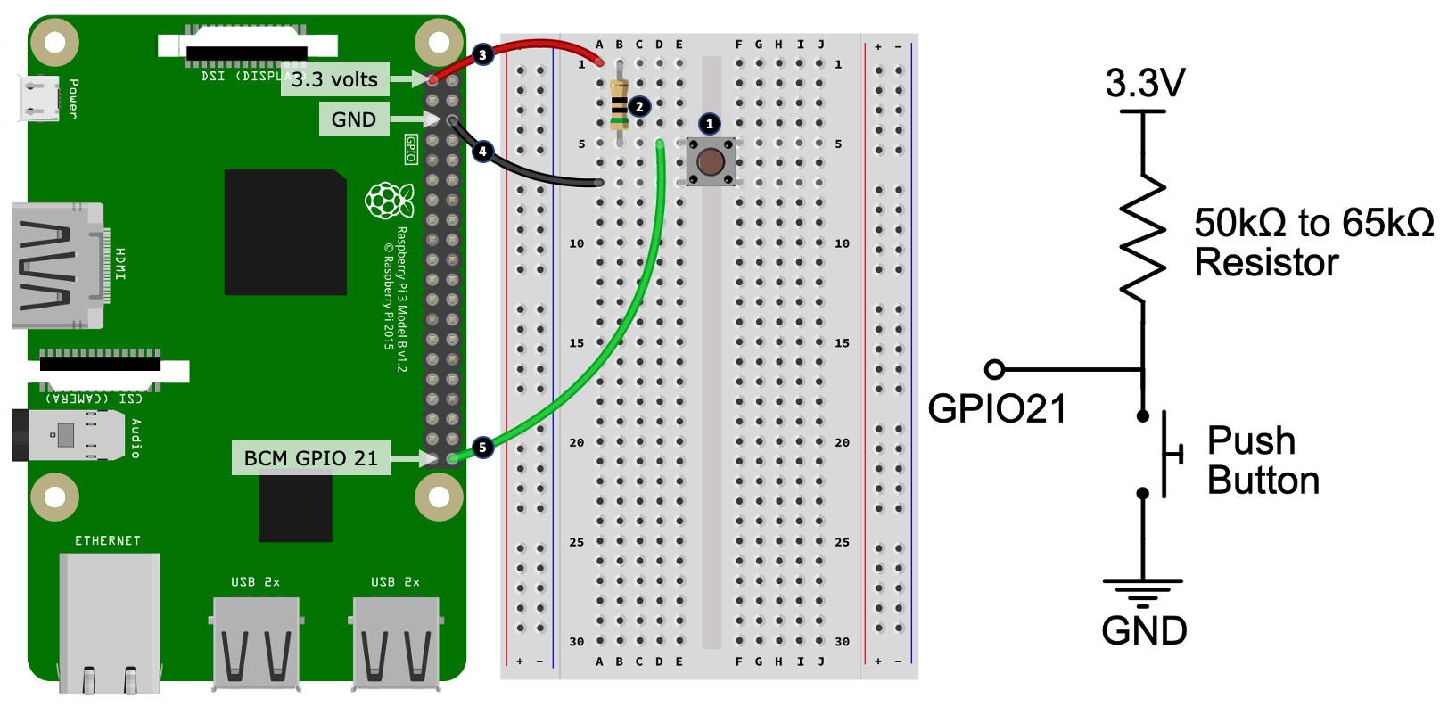
Here are the steps to create this circuit on your breadboard. The step numbers here match the numbered black circles shown in the preceding diagram:
- Place the push button on your breadboard.
- Place the resistor (with a value between 50kΩ to 65kΩ ) on your breadboard. One end of the resistor shares the same row (shown at hole B5) as the upper positioned leg of the push button. The other end of the resistor is placed on an empty row.
- Connect the other end of the resistor to a 3.3-volt pin on your Raspberry Pi.
- Connect the lower leg of the push button to a GND pin on your Raspberry Pi.
- Finally, connect the row shared by the upper leg of the push button and lower leg of the resistor (shown at hold D5) to GPIO 21 on your Raspberry Pi.
Now that you have created the circuit, here is a brief description of how it works:
- When the button is not pressed, the resistor pulls GPIO 21 up to the 3.3-volt pin. Current flows along this path and the pin will read as a guaranteed digital high.
- When the button is pressed, the segment of the circuit connecting GPIO 21 to the ground is created. Because more current flows in this path since it has less (near-zero) resistance, the GPIO pin is connected to the ground, and thus will read as low.
Run the same code in chapter06/digital_input_test.py, only this time, when you touch the wires, the output should not fluctuate.
Why is a 50kΩ to 65kΩ resistor being used in the preceding diagram? Read on – we'll find out why when we look at a code-based alternative to using our own physical resistors.
The code solution
We can solve our floating pin situation in code by telling our Raspberry Pi to activate and connect an embedded pull-up resistor to GPIO 21, which, according to the Raspberry PI's documentation, will be within the range 50kΩ-65kΩ, hence why we stipulated that range in the circuit shown in the previous diagram.
The following diagram shows a circuit similar to the one shown in the preceding diagram, but without the physical resistor in the external circuit. I've added a resistor inside the Raspberry Pi diagram to illustrate the fact that there is a physical resistor hiding away somewhere in the Raspberry Pi's circuitry, even though we can't see it:
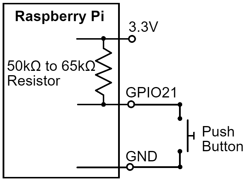
Let's enable a pull-up resistor in code and test this circuit. Here are the steps for you to follow:
- This example uses the push button circuit shown previously in Figure 6.5. Please recreate this circuit on your breadboard before continuing.
- Next, edit the chapter06/digital_input_test.py file to enable an internal pull-up resistor, as follows:
#pi.set_pull_up_down(GPIO_PIN, pigpio.PUD_OFF) <<< COMMENT OUT THIS LINE
pi.set_pull_up_down(GPIO_PIN, pigpio.PUD_UP)   <<< ENABLE THIS LINE
- Run the chapter06/digital_input_test.py file again. As you press the button, you should see the high/low (0/1) values changing on the Terminal; however, touching the wires or Terminals of the button should not cause any interference.
When reading through the preceding code and observing the Terminal output, if the fact that the Terminal prints 1 when the button is not pressed and 0 when it is pressed (that is, button pressed = pin low) seems a bit back to front in a programming sense, then you are right…and wrong. It's because you're looking at the circuit as a programmer. I've done this on purpose because it is a configuration you will see often. This is known as active low, which means the button is active (pressed) when the pin is low.
The opposite resistor setup is also possible and equally valid. That is, you can design the circuit with GPIO 21 pulled to the ground by default, in which case we are employing a pull-down resistor, whether it be a physical resistor or an embedded one activated in code. In this scenario, you will then see that when the button is pressed, the pin reads 1 (high), and it may feel more comfortable in code!
As an exercise, try to change the circuit and code so that it's pull-down by default.
Now that we understand we can have physical and code-activated pull-up and pull-down resistors, can we say that one approach is better than the other? The short answer is, yes, sometimes...external resistors do have an advantage.
The advantage of an external pull-up or pull-down resistor is that they are always present. Code-activated pull-up and pull-downs are only present if two conditions are met:
- Your Raspberry Pi is powered on.
- You have run the code that activates the pull-up or pull-down. Until this happens, the pin is floating! We will look at an application where we prefer an external pull-down resistor in Chapter 7, Turning Things On and Off.
This is not to say that code-activated pull-up and pull-down resistors are inferior, it just means you need to consider the impact of a floating pin for your circuit when your Raspberry Pi is off or you are not running code.
We have now covered the basics of digital input and output, which, in many ways, are the backbone of electronic interfacing. We also learned that there is more going on with digital input than simply a high/on or low/off state in that threshold voltage levels actually determine what voltage level is considered a digital high or a digital low for your Raspberry Pi. In addition to this, we also learned that it is necessary to appropriately employ a pull-up or pull-down resistor when dealing with digital input so that the input circuit is reliable and predictable – that is, it's not floating.
Your understanding of digital I/O will be beneficial to you when designing predictable digital input circuits (floating pins and missing or incorrectly used pull-up or down-down resistors are common sources of errors when starting out!). Furthermore, your understanding of threshold digital high/low voltage levels will be valuable when you are integrating with non-Raspberry Pi devices and electronics. We'll pick up on this digital voltage theme again later in this chapter, in the Logic-level conversion section.
Now, let's move on from digital and explore analog electronics.
Exploring analog electronics
As we saw in the previous section, digital I/O is all about discrete highs or lows, as determined by voltage. Analog I/O, on the other hand, is all about degrees of voltage. In this section, we will explore some core concepts and look at examples of analog I/O in operation.
Analog output
In Chapter 5, Connecting Your Raspberry Pi to the Physical World, we discussed that by using PWM on a digital output pin, we can create a pseudo-analog output or the appearance of a variable output voltage. Furthermore, we also saw PWM in use back in Chapter 3, Networking with RESTful APIs and Web Sockets Using Flask, when we used this concept to control the brightness of an LED.
In this section, we'll explore the idea underlying PWM just a little further with a short exercise. Our example is similar to the one we performed for digital output previously, only this time, we are using PWM to produce a varying voltage on a GPIO pin. Here are the steps we need to follow:
- Connect your multimeter to your Raspberry Pi as we did for digital output in Figure 6.3.
- Run the following code, which you can find in the chapter06/analog_pwm_output_test.py file.
- As the code runs, your multimeter will step through a range of different voltages. They won't be exact, as per the Terminal screen output shown here, but should be reasonably close enough to illustrate the intent:
(venv) $ analog_pwm_output_test.py
Duty Cycle 0%, estimated voltage 0.0 volts
Duty Cycle 25%, estimated voltage 0.825 volts
Duty Cycle 50%, estimated voltage 1.65 volts
Duty Cycle 75%, estimated voltage 2.475 volts
Duty Cycle 100%, estimated voltage 3.3 volts
Let's have a look at the code, which is partly replicated here.
It is using PiGPIO's hardware-timed PWM, which is configured on line 1, while a set of duty cycle percentages are defined on line 2. These are the duty cycle values that our code will step through on line 3. It's on line 4 that we set the duty cycle for GPIO 21 before sleeping for 5 seconds so that you can read the value on the Terminal and your multimeter:
# ... truncated ...
pi.set_PWM_frequency(GPIO_PIN, 8000)                       # (1)

duty_cycle_percentages = [0, 25, 50, 75, 100]              # (2)
max_voltage = 3.3

try:
    while True:
       for duty_cycle_pc in duty_cycle_percentages:        # (3)
           duty_cycle = int(255 * duty_cycle_pc / 100)
           estimated_voltage = max_voltage * duty_cycle_pc / 100
           print("Duty Cycle {}%, estimated voltage {} volts"
                 .format(duty_cycle_pc, estimated_voltage))
           pi.set_PWM_dutycycle(GPIO_PIN, duty_cycle)      # (4)
           sleep(5)

# ... truncated ...
If you ever need to provide a more true form analog output from your Raspberry Pi, then you might like to explore how you can use a Digital-to-Analog Converter (DAC). They will typically interface via I2C or SPI, and you will control them via a driver library similar to the ADS1115 ADC, only you'll be outputting a varying voltage rather than reading one.
Now that we've discussed analog output and seen a simple example of how to create one using PWM, next, we will look at the input side of analog electronics.
Analog input
In Chapter 5, Connecting Your Raspberry Pi to the Physical World, we learned how to use the ADS1115 ADC breakout module, and that analog input is all about measuring a voltage from within a predefined range, which, for our purposes, is between 0 volts and 3.3 volts. While in digital I/O, we'd say 0 volts measured on a pin means low and 3.3 means high, in analog I/O, there are no concepts of high or low in this regard.
Many simple analog components and sensors operate on the principle that their resistance changes in accordance with what they measure. For example, a light dependent resistor, or LDR, changes its resistance in proportion to the light it detects. However, analog input is all about measuring voltage. To turn a varying resistance into a varying voltage, we use a voltage divider circuit.
Voltage dividers
The following diagram shows a simple two-resistor voltage divider circuit. Our resistor values are fixed for this example to illustrate the basic principle. Notice that we've used 5 volts in this example. The reason for this will be revealed shortly when we cover logic-level conversion:

It's a principle of electronics and resistors that voltage is dropped across series resistors in proportion to their resistance. In the preceding circuit, R1 is twice as high as R2, so it drops twice as much voltage. Here is the basic formula, as applied to the preceding circuit (it's actually the application of Kirchhoff's Law and Ohm's Law again):

Vout = 5 volts x 2000Ω / (1000Ω + 2000Ω)
Vout = 3.33333 volts
We'll see the application of voltage dividers in Section 3, IoT Playground – Practical Examples to Interact with the Physical World, but for now, to see this principle in practice and to help cement the concept, apply a digital multimeter across the points marked in the preceding diagram to verify that the measured voltages are close to what's indicated; that is ~1.6 volts across R1 (points A and B in the preceding diagram) and ~3.3 volts across R2 (points B and C). The measurement across R2 (points B and C) is the Vout in the preceding equation.
What about the choice of resistor values? For a voltage divider, the most important part of the resistor value's choices is their relative ratios to divide the voltage in a way we want. Beyond that, it comes down to current flow and resistor power ratings – again, these are applications of Ohm's Law and power.
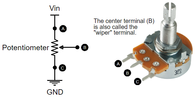
Remember the potentiometers in Chapter 5, Connecting Your Raspberry Pi to the Physical World? They're actually voltage dividers! We had the middle wiper connected to AIN1 and AIN2 of the ADS1115 and when you turned the dial on the potentiometer, what you were doing was changing the resistance across Terminals A and B relative to the center wiper, thus creating the variable voltage that's read by the ADS1115.
The following diagram shows how a potentiometer relates to a semantic diagram. Points A, B, and C are comparable to those indicated in the preceding circuit:
Let's perform an experiment to see how a potentiometer acts as a voltage divider by creating the circuit shown here:
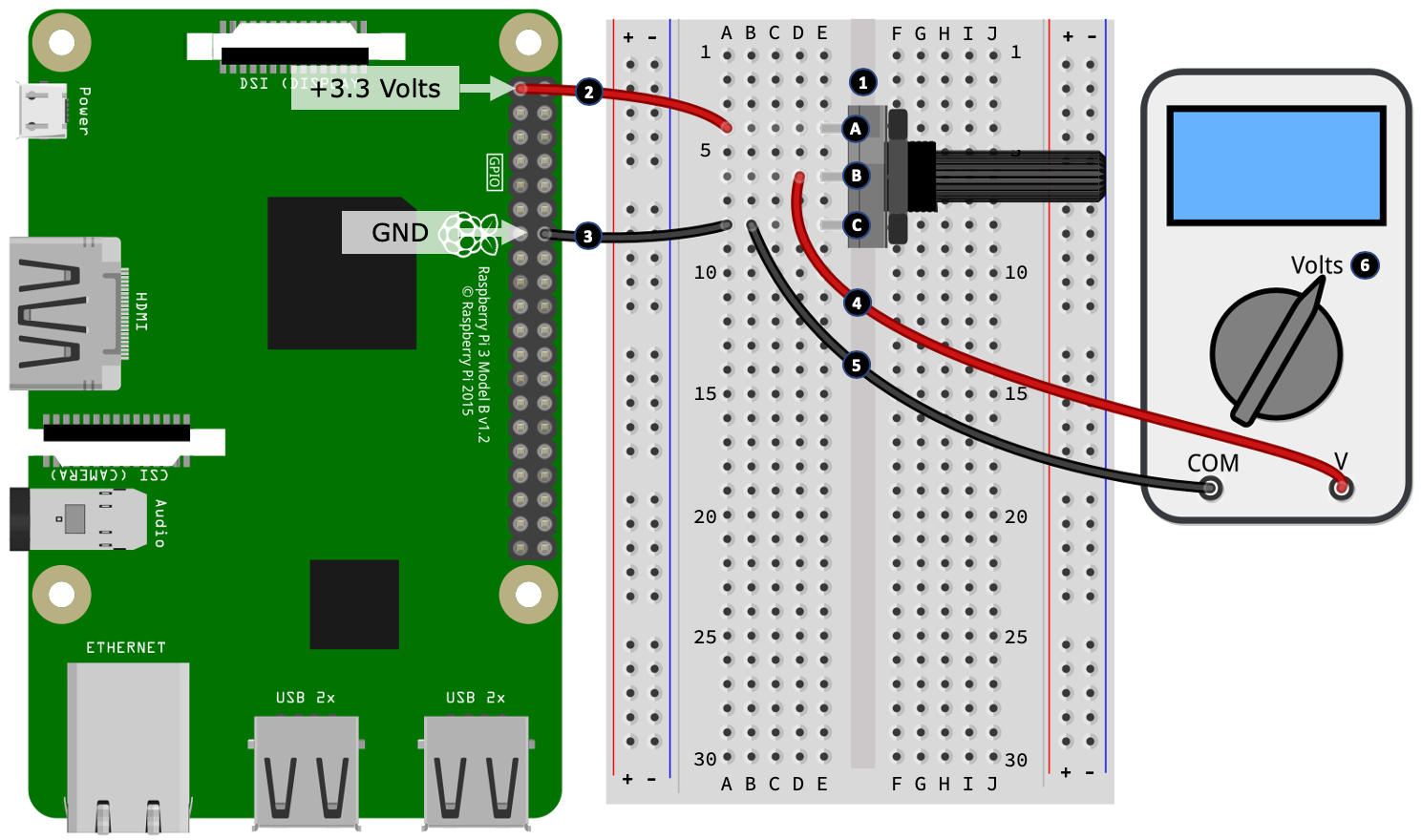
Here are the first set of steps to follow. The step numbers here match the numbered black circles shown in the preceding diagram:
- Place the 10kΩ potentiometer on your breadboard. You'll notice that I have marked Terminals A, B, and C so that they match the labeling shown in Figure 6.9.
- Connect an outer Terminal (labeled A) of the potentiometer to a 3.3-volt pin on your Raspberry Pi. In this circuit, we are only using our Raspberry Pi as a power source. You could use an external power supply or a battery if you desired.
- Connect the alternate outer Terminal (labeled C) of the potentiometer to a Raspberry Pi GND pin.
- Connect the voltage measuring lead from your multimeter to the middle Terminal (labeled B) of the potentiometer.
- Connect the com Terminal of your multimeter to GND (which, in our example, is shared by the potentiometer Terminal labeled C).
- Turn your multimeter on and select its voltage mode.
Now, with your multimeter on, turn the potentiometer's dial and observe the voltage reading on your multimeter change within the range of ~0 volts and ~3.3 volts.
This now concludes our introduction to analog electronics. We performed a simple exercise to demonstrate and visualize, with a multimeter, how PWM produces a variable output voltage. We also learned about voltage dividers, how they work, and why they are a crucial part of any analog input circuit. We finished by revisiting potentiometers once more and looking at how they work as varying voltage dividers.
These analog concepts, while relatively short and simple, are two core principles underlying analog circuits that every electronic engineer – whether you are a professional or a hobbyist – needs to understand. These concepts – especially voltage dividers – will feature in many circuits in upcoming chapters (we will be using them in conjunction with an ADS1115 analog-to-digital converter), so please play around with the preceding examples and principles to ensure you grasp the basics!
Next, we will discuss logic-level conversion and look at another practical application of voltage dividers, only this time in the digital input space.
Understanding logic-level conversion
There will be occasions when you need to interface with 5-volt devices from your Raspberry Pi's 3.3-volt GPIO pins. This interfacing may be for the purpose of GPIO input, output, or bi-directional I/O. The technique used to convert between logic-level voltages is known as logic-level conversion or logic-level shifting.
There are a variety of techniques that can be used to shift voltages, and we will cover two of the more common ones in this section. One uses a voltage divider circuit, which we discussed under the previous heading, while the other uses a dedicated logic-level shifting module. Our first example of logic-level conversion will be to look at a resistor-based solution known as a voltage divider.
Voltage dividers as logic-level converters
A voltage divider circuit constructed of appropriately selected resistors can be used to shift down from 5 volts to 3.3 volts, allowing you to use a 5-volt output from a device as the input to your 3.3-volt Raspberry Pi pin.
The following diagram is the same example we saw previously in Figure 6.8, only this time, it's been drawn within a different context; that is, showing how a 5-volt input can be shifted down to 3.3 volts:

A voltage divider cannot shift up a voltage from 3.3 volts to 5 volts. However, cast your mind back to our discussion on digital input and Figure 6.4, where we explained how an input pin reads a digital high as long as the voltage was >= ~2.0 volts. Well, the same often applies to 5-volt circuits – as long as the input voltage is >= ~2.0 volts (which 3.3 volts is), the 5-volt logic will register a logic high. The digital low works in the same manner too when a voltage of <= ~0.8 volts is applied.
This is often the case, though you will need to check the details and datasheet of the 5-volt device in question. It may mention the minimum voltage explicitly, or may simply mention that it will work with 3.3-volt logic. If there is no obvious indication of the device supporting 3.3-volt logic, you can always test it out yourself using 3.3 volts. This is safe to do because 3.3 volts is less than 5 volts, which means there is no risk of damage. At worst, it just will not work or work unreliably, in which case you can use a dedicated logic-level converter. We'll discuss this next.
Logic-level converter ICs and modules
An alternative to a voltage divider circuit is a dedicated logic-level shifter or converter. They come in IC (chip) form and breadboard-friendly breakout modules. There's no math involved because they are more or less plug and play, and they include multiple channels so that they can convert multiple I/O streams simultaneously.
The following image shows typical 4-channel (left) and 8-channel (right) logic-level conversion breakout modules. The 4-channel on the left is built using MOSFETs, while the 8-channel on the right uses a TXB0108 IC. Please note that while we will cover MOSFETs in Chapter 7, Turning Things On and Off, our focus will be using MOSFETs as switches, not logic-level conversion applications:

Logic-level shifter modules also have two halves – a low voltage side and a high voltage side. In relation to your Raspberry Pi, we connect its 3.3-volt pin and the GPIOs to the low-voltage side, and then connect another higher voltage circuit (for example, a 5-volt circuit) to the high-voltage side.
Let's see level conversion in action. We will do this by building a circuit and measuring the voltage. Previously, in the Digital output section, we connected a multimeter directly to a Raspberry Pi GPIO pin and observed that when the GPIO was high, the multimeter read ~3.3 volts. This time, we will connect our multimeter to the HV side of a logic-level converter and observe that the multimeter reads ~5 volts when the GPIO pin is high.
We will start by building our circuit, which we will do in two parts:

Here are the first set of steps to follow, in which we place the components that wire up the low-voltage side of the logic-level converter. The step numbers here match the numbered black circles shown in the preceding diagram:
- Place your logic-level converter on your breadboard.
- Connect the LV (low voltage) Terminal of the logic-level converter to the positive side of the left-hand side power rail. We will call this rail the low voltage rail because it will be connected to the lower of our supply voltages (that is, 3.3 volts). The LV Terminal is the low voltage side power input Terminal for the logic-level converter.
- Connect the positive side of the low voltage rail to a 3.3-volt power pin on your Raspberry Pi.
- Connect the GND Terminal on the low voltage side of the logical-level converter to the negative rail on the low voltage rail.
- Connect the negative rail on the low voltage rail to a GND pin on your Raspberry Pi.
- Finally, connect port A1 on the logic-level converter to GPIO 21 on your Raspberry Pi.
Next, we'll wire up the high voltage side of the logic-level converter and connect our multimeter:

Here are the second set of steps to follow. The step numbers here match the numbered black circles shown in the preceding diagram:
- Connect the positive rail on the right-hand side power rail to a 5-volt pin on your Raspberry Pi. We will call this rail the high voltage rail because it will be connected to the higher of our supply voltages (that is, 5 volts). The HV Terminal is the high voltage side power input Terminal for the logic-level converter.
- Connect the negative rail of the high voltage rail to the negative rail of the low voltage rail. You may recall that all GND connections are common across a circuit. If you need a refresher on this concept, please revisit the Introducing ground connections and symbols section in Chapter 2, Getting Started with Python and IoT.
- Connect the HV Terminal of the logic-level converter to the positive side of the high voltage rail.
- Connect the GND Terminal on the high voltage side of the logic-level converter to the negative rail of the high voltage rail.
- Connect the voltage-measuring Terminal of your multimeter to port B1 on the logic-level converter.
- Connect the com Terminal of your multimeter to the negative rail of the high voltage rail.
- Finally, set your multimeter to its voltage mode.
Now that we have built our circuit, let's run a Python program and confirm that our multimeter reads ~5 volts when GPIO 21 is high. Here is what we need to do:
- Run the code in the chapter06/digital_output_test.py file – it's the same code we used previously for digital output in the section titled Digital output.
- On the low voltage side, our Raspberry Pi is pulsing GPIO 21 between low (0 volts) and high (3.3 volts) on channel 1 port A1, while on the high voltage side, our multimeter, which is connected to channel 1 port B1, will alternate between 0 and ~5 volts, illustrating the shift of a 3.3-volt logic-level high to a 5-volt logic-level high.
The reverse scenario is also possible; that is, if you applied a 5-volt input to the high voltage side, it will be converted into 3.3 volts on the low voltage side, which can safely be read as input by a 3.3-volt Raspberry Pi GPIO pin.
Building this reverse scenario is an exercise that you might like to try on your own – you already have the core knowledge, code, and circuits to achieve this; you just need to wire it all up! I encourage you to try this, and to get you started, here are some tips:
- Place a push button and pull-up resistor on your breadboard, and wire it up to port B1 on the high voltage side of the logic-level converter. This circuit (schematically) is identical to what you have seen previously in Figure 6.6, except that the source will now be 5 volts, and the GPIO pin is now port B1.
- To test your circuit, you can use the same digital input code we used previously, which can be found in the chapter06/digital_input_test.py file.
- If you get stuck, need a reference breadboard layout, or wish to check your circuit build, you can find a breadboard layout in the chapter06/logic_level_input_breadboard.png file.
Let's conclude our discussion of level conversion by comparing the two approaches we have looked at.
Comparing voltage dividers and logic-level converters
Is one approach better than the other? It depends, though I will say that a dedicated converter will always outshine a basic voltage divider, and they are a lot less fiddly to use with a breadboard. A voltage divider is cheaper to build but only works in a direct direction (you'll need two voltage divider circuits to perform bi-directional I/O). They also have relatively high electrical impedance, meaning that there is a practical delay that occurs between the variable resistance changing and the measurable voltage changing. This delay is enough to make a simple voltage divider impractical for circuits where there is fast switching between high and low states. A dedicated logic-level converter overcomes these limitations, plus they are multi-channel, bi-directional, faster, and more efficient.
Summary
This chapter commenced with a quick overview of the basic tools and equipment that you will need as you get further into electronics and the circuits that we will cover in Section 3 (which we'll be commencing in the next chapter). Then, we went through some suggestions to help keep your Raspberry Pi safe while you are connecting electronics to its GPIO pins, as well as a few tips when it comes to purchasing components.
Then, we explored Ohm's Law (and very briefly Kirchhoff's) before working through the reasons and calculations as to why our LED circuit was using a 200 Ohm resistor. We followed this example by looking at the electronic properties of digital circuits, where we explored logic voltage levels, floating pins, and pull-up and pull-down resistors. We then looked at analog circuits and worked through an example of a voltage divider circuit. We concluded this chapter by looking at logic-level conversion and how you can interface a 5-volt logic device with a 3.3-volt logic device such as your Raspberry Pi.
The goal of this chapter was to introduce you to fundamental electronic principles underpinning basic electronics and, in particular, electronic interfacing to devices such as a Raspberry Pi. I have endeavored to also explain the basic why behind these principles and how they influence what components are chosen for a circuit. Armed with this information, you should now be in a position to better understand how simple circuits are built to work with your Raspberry Pi.
Furthermore, you can leverage this understanding as your starting point to further develop and advance your electronic skills. You'll find links to useful electronic-based websites in the Further reading section, plus we'll see many of these principles in use as we proceed through Section 3, IoT Playground.
When you're ready to get started, I'll see you in the next chapter – which is also the start of Section 3, IoT Playground – where we will explore different methods of switching things on and off.
Questions
As we conclude, here is a list of questions for you to test your knowledge regarding this chapter's material. You will find the answers in the Assessments section of the book:
-
You have a circuit that requires a 200Ω resistor, but you only have a 330Ω resistor available. It is safe to use this value?
- You substitute a higher value resistor in a circuit but the circuit does not work. With respect to Ohm's Law, what could be the problem?
- You calculated a suitable resistor value for a circuit using Ohm's Law, but when you applied power to the circuit, the resistor started to discolor and let off smoke. Why?
- Assuming GPIO 21 is configured via Python as an input pin and it is connected by a wire directly to the +3.3-volt pin, what value will pi.read(21) return?
- You have a push button set up so that when it's pressed, it connects GPIO 21 to a GND pin. When the button is not pressed, you notice that your program is erratic and appears to receive a phantom button press. What could the problem be?
- You want to connect a device that operates its output pins at 5 volts to a Raspberry Pi GPIO input pin. How can you do this safely?
- True or false – A resistor voltage divider circuit can be used to convert a 3.3-volt input into 5 volts for use with a 5-volt logic input device.
Further reading
The following two sites are electronic manufacturers and they both feature a wide range of entry-to-mid-level tutorials. They focus on the practical aspects of electronics and don't bombard you with too much theory. Try a search for Raspberry Pi on their sites:
In relation to the concepts that we have covered in this chapter, here are some specific links on the aforementioned sites:
-
All About LEDs: https://learn.sparkfun.com/tutorials/light-emitting-diodes-leds
-
Ohm's Law, Power, and Kirchhoff's Law Primer: https://learn.sparkfun.com/tutorials/voltage-current-resistance-and-ohms-law
-
Voltage Dividers: https://learn.sparkfun.com/tutorials/voltage-dividers
-
Pull-Up/Down Resistors: https://learn.sparkfun.com/tutorials/pull-up-resistors/all
-
Resistors and Color Codes: https://learn.sparkfun.com/tutorials/resistors
If you want to go deeper, the following two websites are excellent (and free) resources that cover a diverse range of topics on electronic fundamentals and theory:
I recommend spending a few moments just clicking around these sites to get an idea of what they include. That way, if you come across an electronic term, component, or concept in this book that you want to explore further, you'll have an idea where to start your investigation. Here are the two links to begin your exploration:
-
https://www.electronics-tutorials.ws/category/dccircuits (DC Circuit Theory)
-
https://www.allaboutcircuits.com/textbook/direct-current (DC Circuit Theory)
If you browse through the indexes on these sites, you will find sections including Ohm's Law, power, Kirchhoff's Laws, voltage dividers, and digital and analog electronics.