
This chapter presents a sequence of attempts to solve the critical section problem for two processes, culminating in Dekker’s algorithm. The synchronization mechanisms will be built without the use of atomic statements other than atomic load and store. Following this sequence of algorithms, we will briefly present solutions to the critical section problem that use more complex atomic statements. In the next chapter, we will present algorithms for solving the critical section problem for N processes.
Algorithms like Dekker’s algorithm are rarely used in practice, primarily because real systems support higher synchronization primitives like those to be discussed in subsequent chapters (though see the discussion of “fast” algorithms in Section 5.4). Nevertheless, this chapter is the heart of the book, because each incorrect algorithm demonstrates some pathological behavior that is typical of concurrent algorithms. Studying these behaviors within the framework of these elementary algorithms will prepare you to identify and correct them in real systems.
The proofs of the correctness of the algorithms will be based upon the explicit construction of state diagrams in which all scenarios are represented. Some of the proofs are left to the next chapter, because they require more complex tools, in particular the use of temporal logic to specify and verify correctness properties.
We start with a specification of the structure of the critical section problem and the assumptions under which it must be solved:
Each of N processes is executing in a infinite loop a sequence of statements that can be divided into two subsequences: the critical section and the non-critical section.
The correctness specifications required of any solution are:
Mutual exclusion. Statements from the critical sections of two or more processes must not be interleaved.
Freedom from deadlock. If some processes are trying to enter their critical sections, then one of them must eventually succeed.
Freedom from (individual) starvation. If any process tries to enter its critical section, then that process must eventually succeed.
A synchronization mechanism must be provided to ensure that the correctness requirements are met. The synchronization mechanism consists of additional statements that are placed before and after the critical section. The statements placed before the critical section are called the preprotocol and those after it are called the postprotocol. Thus, the structure of a solution for two processes is as follows:
The protocols may require local or global variables, but we assume that no variables used in the critical and non-critical sections are used in the protocols, and vice versa.
The critical section must progress, that is, once a process starts to execute the statements of its critical section, it must eventually finish executing those statements.
The non-critical section need not progress, that is, if the control pointer of a process is at or in its non-critical section, the process may terminate or enter an infinite loop and not leave the non-critical section.
The following diagram will help visualize the critical section problem:
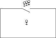
The stick figures represent processes and the box is a critical region in which at most one process at a time may be executing the statements that form its critical section. The solution to the problem is given by the protocols for opening and closing the door to the critical region in such a manner that the correctness properties are satisfied.
The critical section problem is intended to model a system that performs complex computation, but occasionally needs to access data or hardware that is shared by several processes. It is unreasonable to expect that individual processes will never terminate, or that nothing bad will ever occur in the programs of the system. For example, a check-in kiosk at an airport waits for a passenger to swipe his credit card or touch the screen. When that occurs, the program in the kiosk will access a central database of passengers, and it is important that only one of these programs update the database at a time. The critical section is intended to model this operation only, while the non-critical section models all the computation of the program except for the actual update of the database.
It would not make sense to require that the program actually participate in the update of the database by programs in other kiosks, so we allow it to wait indefinitely for input, and we take into account that the program could malfunction. In other words, we do not require that the non-critical section progress. On the other hand, we do require that the critical section progress so that it eventually terminates. The reason is that the process executing a critical section typically holds a “lock” or “permission resource,” and the lock or resource must eventually be released so that other processes can enter their critical sections. The requirement for progress is reasonable, because critical sections are usually very short and their progress can be formally verified.
Obviously, deadlock (“my computer froze up”) must be avoided, because systems are intended to provide a service. Even if there is local progress within the protocols as the processes set and check the protocol variables, if no process ever succeeds in making the transition from the preprotocol to the critical section, the program is deadlocked.
Freedom from starvation is a strong requirement in that it must be shown that no possible execution sequence of the program, no matter how improbable, can cause starvation of any process. This requirement can be weakened; we will see one example in the algorithm of Section 5.4.
A good solution to the critical section problem will also be efficient, in the sense that the pre- and postprotocols will use as little time and memory as possible. In particular, if only a single process wishes to enter its critical section it will succeed in doing so almost immediately.
Here is a first attempt at solving the critical section problem for two processes:
The statement await turn=1 is an implementation-independent notation for a statement that waits until the condition turn=1 becomes true. This can be implemented (albeit inefficiently) by a busy-wait loop that does nothing until the condition is true.
The global variable turn can take the two values 1 and 2, and is initially set to the arbitrary value 1. The intended meaning of the variable is that it indicates whose “turn” it is to enter the critical section. A process wishing to enter the critical section will execute a preprotocol consisting of a statement that waits until the value of turn indicates that its turn has arrived. Upon exiting the critical section, the process sets the value of turn to the number of the other process.
We want to prove that this algorithm satisfies the three properties required of a solution to the critical section problem. To that end we first explain the construction of state diagrams for concurrent programs, a concept that was introduced in Section 2.2.
You do not need to know the history of the execution of an algorithm in order to predict the result of the next step to be executed. Let us first examine this claim for sequential algorithms and then consider how it has to be modified for concurrent algorithms. Consider the following algorithm:
Suppose now that the computation has reached statement p2, and the values of a and b are 10 and 20, respectively. You can now predict with absolute certainty that as a result of the execution of statement p2, the value of a will become 150, while the value of b will remain 20; furthermore, the control pointer of the computer will now contain p3. The history of the computation—how exactly it got to statement p2 with those values of the variables—is irrelevant.
For a concurrent algorithm, the situation is similar:
Suppose that the execution has reached the point where the first process has reached statement p2 and the second has reached q2, and the values of a and b are again 10 and 20, respectively. Because of the interleaving, we cannot predict whether the next statement to be executed will come from process p or from process q; but we can predict that it will be from either one or the other, and we can specify what the outcome will be in either case.
In the sequential Algorithm 3.3, states are triples such as si = (p2, 10, 20). From the semantics of assignment statements, we can predict that executing the statement p2 in state si will cause the state of the computation to change to si+1 = (p3, 150, 20). Thus, given the initial state of the computation s0 = (p1, 1, 2), we can predict the result of the computation. (If there are input statements, the values placed into the input variables are also part of the state.) It is precisely this property that makes debugging practical: if you find an error, you can set a breakpoint and restart a computation in the same initial state, confident that the state of the computation at the breakpoint is the same as it was in the erroneous computation.
In the concurrent Algorithm 3.4, states are quadruples such as si = (p2, q2, 10, 20). We cannot predict what the next state will be, but we can be sure that it is either ![]() or
or ![]() ) depending on whether the next state taken is from process
) depending on whether the next state taken is from process p or process q, respectively. While we cannot predict which states will appear in any particular execution of a concurrent algorithm, the set of reachable states (Definition 2.5) are the only states that can appear in any computation. In the example, starting from state si, the next state will be an element of the set ![]() . From each of these states, there are possibly two new states that can be reached, and so on. To check correctness properties, it is only necessary to examine the set of reachable states and the transitions among them; these are represented in the state diagram.
. From each of these states, there are possibly two new states that can be reached, and so on. To check correctness properties, it is only necessary to examine the set of reachable states and the transitions among them; these are represented in the state diagram.
For the first attempt, Algorithm 3.2, states are triples of the form (pi, qj, turn), where turn denotes the value of the variable turn. Remember that we are assuming that any variables used in the critical and non-critical sections are distinct from the variables used in the protocols and so cannot affect the correctness of the solution. Therefore, we leave them out of the description of the state. The mutual exclusion correctness property holds if the set of all accessible states does not contain a state of the form (p3, q3, turn) for some value of turn, because p3 and q3 are the labels of the critical sections.
How many states can there be in a state diagram? Suppose that the algorithm has N processes with ni statements in process i, and M variables where variable j has mj possible values. The number of possible states is the number of tuples that can be formed from these values, and we can choose each element of the tuple independently, so the total number of states is n1 × . . . × nN × m1 . . . × mM. For the first attempt, the number of states is n1 × n2 × m1 = 4 × 4 × 2 = 32, since it is clear from the text of the algorithm that the variable turn can only have two values, 1 and 2. In general, variables may have as many values as their representation can hold, for example, 232 for a 32-bit integer variable.
However, it is possible that not all states can actually occur, that is, it is possible that some states do not appear in any scenario starting from the initial state s 0 = (p1, q1, 1). In fact, we hope so! We hope that the states (p3, q3, 1) and (p3, q3, 2), which violate the correctness requirement of mutual exclusion, are not accessible from the initial state.
To prove a property of a concurrent algorithm, we construct a state diagram and then analyze if the property holds in the diagram. The diagram is constructed incrementally, starting with the initial state and considering what the potential next states are. If a potential next state has already been constructed, then we can connect to it, thus obtaining a finite presentation of an unbounded execution of the algorithm. By the nature of the incremental construction,turn will only have the values 1 and 2, because these are the only values that are ever assigned by the algorithm.
The following diagram shows the first four steps of the incremental construction of the state diagram for Algorithm 3.2:
The initial state is (p1, q1, 1). If we execute p1 from process p, the next state is (p2, q1, 1): the first element of the tuple changes because we executed a statement of the first process, the second element does not change because we did not execute a statement of that process, and the third element does not change since—by assumption—the non-critical section does not change the value of the variable turn. If, however, we execute q1 from process q, the next state is (p1, q2, 1). From this state, if we try to execute another statement, q2, from process q, we remain in the same state. The statement is await turn=2, but turn = 1. We do not draw another instance of (p1, q2, 1); instead, the arrow representing the transition points to the existing state.
The incremental construction terminates after 16 of the 32 possible states have been constructed, as shown in Figure 3.1. You may (or may not!) want to check if the construction has been carried out correctly.
A quick check shows that neither of the states (p3, q3, 1) nor (p3, q3, 2) occurs; thus we have proved that the mutual exclusion property holds for the first attempt.
Clearly, the state diagram of the simple algorithm in the first attempt is unwieldy. When state diagrams are built, it is important to minimize the number of states that must be constructed. In this case, we can reduce the number of accessible states from 16 to 4, by reducing the algorithm to the one shown below, where we have removed the two statements for the critical and non-critical sections.
Admittedly, this is suspicious. The whole point of the algorithm is to ensure that mutual exclusion holds during the execution of the critical sections, so how can we simply erase these statements? The answer is that whatever statements are executed by the critical section are totally irrelevant to the correctness of the synchronization algorithm.
If in the first attempt, we replace the statement p3: critical section by the comment p3: // critical section, the specification of the correctness properties remain unchanged, for example, we must show that we cannot be in either of the states (p3, q3, 1) or (p3, q3, 2). But if we are at p3 and that is a comment, it is just as if we were at p4, so we can remove the comment; similar reasoning holds for p1. In the abbreviated first attempt, the critical sections have been “swallowed up” by turn ← 2 and turn ← 1, and the non-critical sections have been “swallowed up” by await turn=1 and await turn=2. The state diagram for this algorithm is shown in Figure 3.2, where for clarity we have given the actual statements and variables names instead of just labels.
We are now in a position to try to prove the correctness of the first attempt. As noted above, the proof that mutual exclusion holds is immediate from an examination of the state diagram.
Next we have to prove that the algorithm is free from deadlock. Recall that this means that if some processes are trying to enter their critical section then one of them must eventually succeed. In the abbreviated algorithm, a process is trying to enter its critical section if it is trying to execute its await statement. We have to check this for the four states; since the two left states are symmetrical with the two right states, it suffices to check one of the pairs.
Consider the upper left state (await turn=1, await turn=2, turn = 2). Both processes are trying to execute their critical sections; if process q tries to execute await turn=2, it will succeed and enter its critical section.
Consider now the lower left state (await turn=1, turn ← 1, turn = 2). Process p may try to execute await turn=1, but since turn = 2, it does not change the state. By the assumption of progress on the critical section and the assignment statement, process q will eventually execute turn ← 1, leading to the upper right state. Now, process p can enter its critical section. Therefore, the property of freedom from deadlock is satisfied.
Finally, we have to check that the algorithm is free from starvation, meaning that if any process is about to execute its preprotocol (thereby indicating its intention to enter its critical section), then eventually it will succeed in entering its critical section. The problem will be easier to understand if we consider the state diagram for the unabbreviated algorithm; the appropriate fragment of the diagram is shown in Figure 3.3, where NCS denotes the non-critical section. Consider the state at the lower left. Process p is trying to enter its critical section by executing p2: await turn=1, but since turn = 2, the process will loop indefinitely in its await statement until process q executes q4: turn←1. But process q is at q1: NCS and there is no assumption of progress for non-critical sections. Therefore, starvation has occurred: process p is continually checking the value of turn trying to enter its critical section, but process q need never leave its non-critical section, which is necessary if p is to enter its critical section.
Informally, turn serves as a permission resource to enter the critical section, with its value indicating which process holds the resource. There is always some process holding the permission resource, so some process can always enter the critical section, ensuring that there is no deadlock. However, if the process holding the permission resource remains indefinitely in its non-critical section—as allowed by the assumptions of the critical section problem—the other process will never receive the resource and will never enter its critical section. In our next attempt, we will ensure that a process in its non-critical section cannot prevent another one from entering its critical section.
The first attempt was incorrect because both processes set and tested a single global variable. If one process dies, the other is blocked. Let us try to solve the critical section problem by providing each process with its own variable (Algorithm 3.6). The intended interpretation of the variables is that wanti is true from the step where process i wants to enter its critical section until it leaves the critical section. await statements ensure that a process does not enter its critical section while the other process has its flag set. This solution does not suffer from the problem of the previous one: if a process halts in its non-critical section, the value of its variable want will remain false and the other process will always succeed in immediately entering its critical section.
Let us construct a state diagram for the abbreviated algorithm:
Unfortunately, when we start to incrementally construct the state diagram (Figure 3.4), we quickly find the state (p3: wantp←false, q3: wantq←false,true, true), showing that the mutual exclusion property is not satisfied. (await !want is used instead of await want=false because of space constraints in the node.)
Paths in the state diagram correspond to scenarios; this portion of the scenario can also be displayed in tabular form:
|
|
|
|
|
| false | false |
|
| false | false |
|
| false | false |
|
| true | false |
|
| true | true |
To prove that mutual exclusion holds, we must check that no forbidden state appears in any scenario. So if mutual exclusion does in fact hold, we need to construct the full state diagram for the algorithm, because every path in the diagram is a scenario; then we must examine every state to make sure that it is not a forbidden state. When constructing the diagram incrementally, we check each state as it is created, so that we can stop the construction if a forbidden state is encountered, as it was in this case. It follows that if the incremental construction is completed (that is, there are no more reachable states), then we know that no forbidden states occur.
In the second attempt, we introduced the variables want that are intended to indicate when a process is in its critical section. However, once a process has successfully completed its await statement, it cannot be prevented from entering its critical section. The state reached after the await but before the assignment to want is effectively part of the critical section, but the value of want does not indicate this fact. The third attempt (Algorithm 3.8) recognizes that the await statement should be considered part of the critical section by moving the assignment to want to before the await. We leave it as an exercise to construct the state diagram for this algorithm, and to show that no state in the diagram violates mutual exclusion. In Section 4.2, we will use logic to prove deductively that the algorithm satisfies the mutual exclusion property.
Unfortunately, the algorithm can deadlock as shown by the following scenario:
|
|
|
|
|
| false | false |
|
| false | false |
|
| false | false |
|
| true | false |
|
| true | true |
This can also be seen in the following fragment of the state diagram:
In the rightmost state, both process are trying to enter the critical section, but neither will ever do so, which is our definition of deadlock.
The term deadlock is usually associated with a “frozen” computation where nothing whatsoever is being computed; the situation here—a scenario where several processes are actively executing statements, but nothing useful gets done—is also called livelock.
In the third attempt, when a process sets the variable want to true, not only does it indicate its intention to enter its critical section, but also insists on its right to do so. Deadlock occurs when both processes simultaneously insist on entering their critical sections. The fourth attempt to solve the critical section problem tries to remedy this problem by requiring a process to give up its intention to enter its critical section if it discovers that it is contending with the other process (Algorithm 3.9). The assignment p4: wantp←false followed immediately by an assignment to the same variable p5: wantp←true would not be meaningful in a sequential algorithm, but it can be useful in a concurrent algorithm. Since we allow arbitrary interleaving of statements from the two processes, the second process may execute an arbitrary number of statements between the two assignments to wantp. When process p relinquishes the attempt to enter the critical section by resetting wantp to false, process q may now execute the await statement and succeed in entering its critical section.
Table 3.9. Fourth attempt
| |
|
|
loop forever p1: non-critical section p2: wantp ← true p3: while wantq p4: wantp ← false p5: wantp ← true p6: critical section p7: wantp ← false |
loop forever q1: non-critical section q2: wantq ← true q3: while wantp q4: wantq ← false q5: wantq ← true q6: critical section q7: wantq ← false |
A state diagram or deductive proof will show that the mutual exclusion property is satisfied and that there is no deadlock. However, a scenario for starvation exists as shown by the cycle in Figure 3.5. The interleaving is “perfect” in the sense that the execution of a statement by process q is always followed immediately by the execution of the equivalently-numbered statement in process p. In this scenario, both processes are starved.
At this point, most people object that this is not a “realistic” scenario; we can hardly expect that whatever is causing the interleaving can indefinitely ensure that exactly two statements are executed by process q followed by exactly two statements from p. But our model of concurrency does not take probability into account. Unlikely scenarios have a nasty way of occurring precisely when a bug would have the most dangerous and costly effects. Therefore, we reject this solution, because it does not fully satisfy the correctness requirements.
Dekker’s algorithm for solving the critical section problem is a combination of the first and fourth attempts:
Table 3.10. Dekker’s algorithm
boolean wantp ← false, wantq ← false integer turn ← 1 | ||
|
| |
loop forever p1: non-critical section p2: wantp ← true p3: while wantq p4: if turn = 2 p5: wantp ← false p6: await turn = 1 p7: wantp ← true p8: critical section p9: turn ← 2 p10: wantp ← false |
loop forever q1: non-critical section q2: wantq ← true q3: while wantp q4: if turn = 1 q5: wantq ← false q6: await turn = 2 q7: wantq ← true q8: critical section q9: turn ← 1 q10: wantq ← false | |
Recall that in the first attempt we explicitly passed the right to enter the critical section between the processes. Unfortunately, this caused the processes to be too closely coupled and prevented correct behavior in the absence of contention. In the fourth attempt, each process had its own variable which prevented problems in the absence of contention, but in the presence of contention both processes insist on entering their critical sections.
Dekker’s algorithm is like the fourth attempted solution, except that the right to insist on entering, rather than the right to enter, is explicitly passed between the processes. The individual variables wantp and wantq ensure mutual exclusion. Suppose now that process p detects contention by finding wantq to be true at statement p3: while wantq. Process p will now consult the global variable turn to see if it is its turn to insist upon entering its critical section (turn ≠ 2, that is,turn = 1). If so, it executes the loop at p3 and p4 until process q resets wantq to false, either by terminating its critical section at q10 or by deferring in q5. If not, process p will reset wantp to false and defer to process q, waiting until that process changes the value of turn after executing its critical section.
Dekker’s algorithm is correct: it satisfies the mutual exclusion property and it is free from deadlock and starvation. The correctness properties by can be proved by constructing and analyzing a state diagram, but instead we will give a deductive proof in Section 4.5.
We have found that it is difficult to solve the critical section problem using just atomic load and store statements. The difficulty disappears if an atomic statement can both load and store. The solutions given here are shown for two processes, but they are correct for any number of processes.
The test-and-set statement is an atomic statement defined as the execution of the following two statements with no possible interleaving between them:
test −and−set(common, local) is
   local ← common
   common ← 1
Table 3.11. Critical section problem with test-and-set
| |
|
|
    integer local1
    loop forever
p1:    non-critical section
       repeat
p2:       test-and-set(
             common, local1)
p3:    until local1 = 0
p4:    critical section
p5: common ← 0 |
    integer local2
    loop forever
q1:    non-critical section
       repeat
q2:       test-and-set(
             common, local2)
q3:    until local2 = 0
q4:    critical section
q5: common ← 0 |
Table 3.12. Critical section problem with exchange
|
|
   integer local1 ← 0
   loop forever
p1:   non-critical section
      repeat
p2:      exchange(common, local1)
p3:   until local1 = 1
p4:   critical section
p5: exchange(common, local1) |
   integer local2 ← 0
   loop forever
q1:   non-critical section
      repeat
q2:      exchange(common, local2)
q3:   until local2 = 1
q4:   critical section
q5: exchange(common, local2) |
Algorithm 3.11 is the simple solution to the critical section problem using test-and-set. We leave it as an exercise to prove that this solution satisfies the mutual exclusion property.
Note: A commonly used notation for specifying atomicity is to put angled brackets around the group of statements: <local ← common; common ← 1>. In Promela, the keyword atomic is used.
The exchange statement is an atomic statement defined as the atomic swap of the values of two variables:
exchange(a, b) is
   integer temp
   temp ← a
   a ← b
   b ← temp
The solution to the critical section problem with exchange is also very simple (Algorithm 3.12). Here too, the proof of correctness is left as an exercise.
We conclude with two other atomic statements that have been implemented in computers; in the exercises you are asked to solve the critical section problem using these statements.
The fetch-and-add statement is defined as the atomic execution of the following statements:
fetch −and−add(common, local, x) is
    local ← common
    common ← common + x
The compare-and-swap statement is defined as the atomic execution of the following statements:
compare−and−swap(common, old, new) is
  integer temp
  temp ← common
  if common = old
     common ← new
  return temp
These solutions use busy-wait loops, but this is not a disadvantage in a multiprocessor, especially if the contention is low.
This chapter introduced the basic concepts of writing a concurrent program to solve a problem. Even in the simplest model of atomic load and store of shared memory, Dekker’s algorithm can solve the critical section problem, although it leaves much to be desired in terms of simplicity and efficiency. Along the journey to Dekker’s algorithm, we have encountered numerous ways in which concurrent programs can be faulty. Since it is impossible to check every possible scenario for faults, state diagrams are an invaluable tool for verifying the correctness of concurrent algorithms.
The next chapter will explore verification of concurrent programming in depth, first using invariant assertions which are relatively easy to understand and use, and then using deductive proofs in temporal logic which are more sophisticated. Finally, we show how programs can be verified using the Spin model checker.
1. | Complete the state diagram for the abbreviated version of the second attempt (Figure 3.4). | |||||||||
2. | Construct the state diagram for (an abbreviated version of) the third attempt (Algorithm 3.8). Use it to show that mutual exclusion holds for the algorithm. | |||||||||
3. | For the fourth attempt (Algorithm 3.9):
| |||||||||
4. | Peterson’s algorithm for the critical section problem is based upon Dekker’s algorithm but is more concise because it collapses two Table 3.13. Peterson’s algorithm
(In our presentation, the compound condition is atomic because it is in one labeled line; the algorithm also works if the two conditions are evaluated non-atomically.) | |||||||||
5. | (Buhr and Haridi [16]) Compare the use of the variable | |||||||||
6. | (Manna and Pnueli [51, p. 156]) Prove that mutual exclusion is satisfied by the following algorithm for the critical section problem: Table 3.14. Manna–Pnueli algorithm
Note that the | |||||||||
7. | (Doran and Thomas [26]) Prove the correctness of the following variant of Dekker’s algorithm: Table 3.15. Doran–Thomas algorithm
| |||||||||
8. | (Lamport [38]) Consider possible solutions of the critical section problem with one bit per process. (Assume that the initial value of all bits is 0.) Show that there are no solutions of the following forms:
| |||||||||
9. | Prove the correctness of Algorithm 3.11 for the critical section problem using test-and-set. | |||||||||
10. | Prove the correctness of Algorithm 3.12 for the critical section problem using exchange. | |||||||||
11. | Solve the critical section problem using fetch-and-add. | |||||||||
12. | Solve the critical section problem using compare-and-swap. | |||||||||