
Using the Class Designer to create a graphical visualization of your class architecture
Easily generating and refactoring your classes with the Class Designer
Using the Modeling Power Toys for Visual Studio 2010 add-in to better work with large class hierarchies
Traditionally, software modeling has been performed separately from coding, often during a design phase that is completed before coding begins. More often than not, the modeling diagrams that are constructed during design are not kept up to date as the development progresses, and they quickly lose their value as design changes are inevitably made.
The Class Designer in Visual Studio 2010 brings modeling into the IDE, as an activity that can be performed at any time during a development project. Class diagrams are constructed dynamically from the source code, which means that they are always up to date. Any change made to the source code is immediately reflected in the class diagram, and any change to the diagram is also made to the code.
This chapter looks at the Class Designer in detail and explains how you can use it to design, visualize, and refactor your class architecture.
The design process for an application typically involves at least a sketch of the classes that are going to be created and how they interact. Visual Studio 2010 provides a design surface, called the Class Designer, onto which classes can be drawn to form a class diagram. Fields, properties, and methods can then be added to the classes, and relationships can be established between classes. Although this design is called a class diagram, it supports classes, structures, enumerations, interfaces, abstract classes, and delegates.
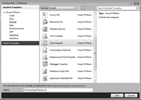
There is more than one way to add a Class Diagram to your project. One way to add a Class Diagram is through the Add New Item dialog, as shown in Figure 10-1. This will create a new blank Class Diagram within the project.
You can also add a new Class Diagram to your project by selecting the View Class Diagram button from the toolbar in the Solution Explorer window or by right-clicking a project or class and selecting the View Class Diagram menu item. If the project is selected when you create a Class Diagram in this way, Visual Studio will automatically add all the types defined within the project to the initial class diagram. Although this may be desirable in some instances, for a project that contains a large number of classes the process of creating and laying out the diagram can be quite time consuming.
Unlike some tools that require all types within a project to be on the same diagram, the class diagram can include as many or as few of your types as you want. This makes it possible to add multiple class diagrams to a single solution.
Note
The scope of the Class Designer is limited to a single project. You cannot add types to a class diagram that are defined in a different project, even if it is part of the same solution.
The Class Designer can be divided into four components: the design surface, the Toolbox, the Class Details window, and the property grid. Changes made to the class diagram are saved in a .cd file, which works in parallel with the class code files to generate the visual layout shown in the Class Designer.
The design surface of the Class Designer enables the developer to interact with types using a drag-and-drop-style interface. You can add existing types to the design surface by dragging them from either the class view or the Solution Explorer. If a file in the Solution Explorer contains more than one type, they are all added to the design surface.
Figure 10-2 shows a simple class diagram that contains two classes, Customer and Order, and an enumeration, OrderStatus. Each class contains fields, properties, methods, and events. There is an association between the classes, because a Customer class contains a property called Orders that is a list of Order objects, and the Order class implements the IDataErrorInfo interface. All this information is visible from this class diagram.
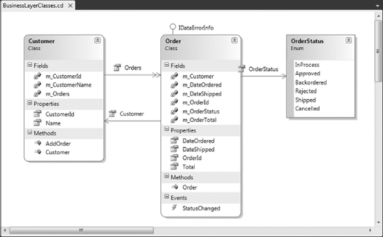
Each class appears as an entity on the class diagram, which can be dragged around the design surface and resized as required. A class is made up of fields, properties, methods, and events. In Figure 10-2, these components are grouped into compartments. You can select alternative layouts for the class diagram, such as listing the components in alphabetical order or grouping the components by accessibility.
The Class Designer is often used to view multiple classes to get an understanding of how they are associated. In this case, it is convenient to hide the components of a class to simplify the diagram. To hide all the components at once, use the toggle in the top-right corner of the class on the design surface. If only certain components need to be hidden, they can be individually hidden, or the entire compartment can be hidden, by right-clicking the appropriate element and selecting the Hide menu item.
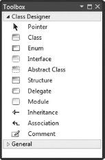
To facilitate items being added to the class diagram there is a Class Designer tab in the Toolbox. To create an item, drag the item from the Toolbox onto the design surface or simply double-click it. Figure 10-3 shows the Toolbox with the Class Designer tab visible. The items in the Toolbox can be classified as either entities or connectors. Note the Comment item, which can be added to the Class Designer but does not appear in any of the code; it is there simply to aid documentation of the class diagram.
The entities that can be added to the class diagram all correspond to types in the .NET Framework. When you add a new entity to the design surface, you need to give it a name. In addition, you need to indicate whether it should be added to a new file or an existing file.
You can remove entities from the diagram by right-clicking and selecting the Remove From Diagram menu item. This does not remove the source code; it simply removes the entity from the diagram. In cases where it is desirable to delete the associated source code, select the Delete Code menu item.
You can view the code associated with an entity by either double-clicking the entity or selecting View Code from the right-click context menu.
The following list explains the entities in the Toolbox:
Class: Fields, properties, methods, events, and constants can all be added to a class via the right-click context menu or the Class Details window. Although a class can support nested types, they cannot be added using the Designer surface. Classes can also implement interfaces. In Figure 10-2, the
Orderclass implements the IDataErrorInfo interface.Enum: An enumeration can only contain a list of members that can have a value assigned to them. Each member also has a summary and remarks property, but these appear only as an XML comment against the member.
Interface: Interfaces define properties, methods, and events that a class must implement. Interfaces can also contain nested types, but recall that adding a nested type is not supported by the Designer.
Abstract Class: Abstract classes behave the same as classes except that they appear on the design surface with an italic name and are marked as
Abstract(C#) orMustInherit(VB).Structure: A structure is the only entity, other than a comment, that appears on the Designer in a rectangle. Similar to a class, a structure supports fields, properties, methods, events, and constants. It, too, can contain nested types. However, unlike a class, a structure cannot have a destructor.
Delegate: Although a delegate appears as an entity on the class diagram, it can't contain nested types. The only components it can contain are parameters that define the delegate signature.
Two types of relationships can be established between entities. These are illustrated on the class diagram using connectors, and are explained in the following list:
If a relationship is based around a collection — for example, a list of Order objects — this can be represented using a collection association. A collection association called Orders is shown in Figure 10-2 connecting the Customer and Order classes.
A class association can be represented as either a field or property of a class, or as an association link between the classes. You can use the right-click context menu on either the field or property or the association to toggle between the two representations.
Note
To show a property as a collection association you need to right-click the property in the class and select Show as Collection Association. This hides the property from the class and displays it as a connector to the associated class on the diagram.
You can add a component to an entity by right-clicking and selecting the appropriate component to add. Unfortunately, this is a time-consuming process and doesn't afford you the ability to add method parameters or return values. The Class Designer in Visual Studio 2010 includes a Class Details window, which provides a user interface that enables components to be quickly entered. This window is illustrated in Figure 10-4 for the Customer class previously shown in Figure 10-2.
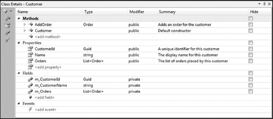
On the left side of the window are buttons that can aid in navigating classes that contain a large number of components. The top button can be used to add methods, properties, fields, or events to the class. The remaining buttons can be used to bring any of the component groups into focus. For example, the second button is used to navigate to the list of methods for the class. You can navigate between components in the list using the up and down arrow keys.
Because Figure 10-4 shows the details for a class, the main region of the window is divided into four alphabetical lists: Methods, Properties, Fields, and Events. Other entity types may have other components, such as Members and Parameters. Each row is divided into five columns that show the name, the return type, the modifier or accessibility of the component, a summary, and whether the item is hidden on the design surface. In each case, the Summary field appears as an XML comment against the appropriate component. Events differ from the other components in that the Type column must be a delegate. You can navigate between columns using the left and right arrow keys, Tab (next column), and Shift+Tab (previous column).
To enter parameters on a method, use the right arrow key to expand the method node so that a parameter list appears. Selecting the Add Parameter node adds a new parameter to the method. Once added, the new parameter can be navigated to by using the arrow keys.
Although the Class Details window is useful it does not provide all the information required for entity components. For example, properties can be marked as read-only, which is not displayed in the Class Details window. The Properties window in Figure 10-5 shows the full list of attributes for the Orders property of the Customer class.
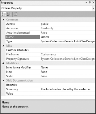
Figure 10-5 shows that the Orders property is read-only and that it is not static. It also shows that this property is defined in the Customer.cs file. With partial classes, a class may be separated over multiple files. When a partial class is selected, the File Name property shows all files defining that class as a comma-delimited list. Although some of these properties are read-only in this window, they can, of course, be adjusted within the appropriate code file.
Because the class diagram is all about visualizing classes, you have several toolbar controls at your disposal to create the layout of the entities on the Designer. Figure 10-6 shows the toolbar that appears as part of the Designer surface.
The first three buttons control the layout of entity components. From left to right, the buttons are Group by Kind, Group by Access, and Sort Alphabetically.
The next two buttons are used to automate the process of arranging the entities on the design surface. On the left is the Layout Diagram button, which automatically repositions the entities on the design surface. It also minimizes the entities, hiding all components. The right button, Adjust Shapes Width, adjusts the size of the entities so that all components are fully visible. If a single component is selected, the "Adjust Shapes Width" button adjusts the width of only that component. If no components are selected, the width of all components are adjusted.
Entity components, such as fields, properties, and methods, can be hidden using the Hide Member button.
The display style of entity components can be adjusted using the next three buttons. The left button, Display Name, sets the display style to show only the name of the component. This can be extended to show both the name and the component type using the Display Name and Type button. The right button, Display Full Signature, sets the display style to be the full component signature. This is often the most useful, although it takes more space to display.
The remaining controls on the toolbar enable you to zoom in and out on the Class Designer, and to display the Class Details window.
Quite often, the process of designing which classes will be part of the system architecture is a part of a much larger design or review process. Therefore, it is a common requirement to export the class diagram for inclusion in reports.
You can export a class diagram either by right-clicking the context menu from any space on the Class Designer or via the Class Diagram menu. Either way, selecting the Export Diagram as Image menu item opens a dialog prompting you to select an image format and filename for saving the diagram.
You can also copy and paste an image directly into Microsoft Word or a drawing program such as Visio. To do this, you must first select one or more classes on the diagram.
Lastly, you can also print Class Diagrams directly from Visual Studio through the normal File
One of the core goals of Visual Studio 2010 and the .NET Framework is to reduce the amount of code that developers have to write. This goal is achieved in two ways: either reduce the total amount of code that has to be written or reduce the amount that actually has to be written manually. The first approach is supported through a very rich set of base classes included in the .NET Framework. The second approach, reduce the amount of code that is written manually, is supported by the code generation and refactoring tools included with the Class Designer.
Almost every action performed on the class diagram results in a change in the underlying source code, and essentially provides some level of code generation. We've already covered a number of these changes, such as adding a property or method to a class in the Class Details window. However, some more advanced code generation actions can be performed by manipulating the class diagram.
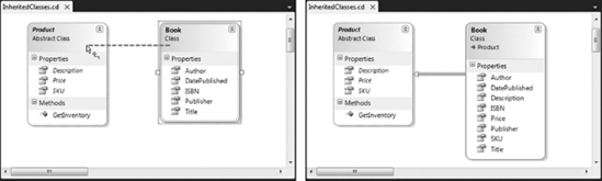
As explained earlier in the chapter, you can use the Inheritance connector to establish an inheritance relationship between a parent class and an inheriting class. When you do this, the code file of the derived class is updated to reflect this change. However, when the parent class is abstract, as in the case of the Product class in Figure 10-7, the Class Designer can perform some additional analysis and code generation. If the parent class is an abstract class and contains any abstract members, those members are automatically implemented in the inheriting classes. This is shown in Figure 10-7 (right) where the abstract properties Description, Price, and SKU have been added to the Book class. The method GetInventory() was not implemented because it was not marked as abstract.
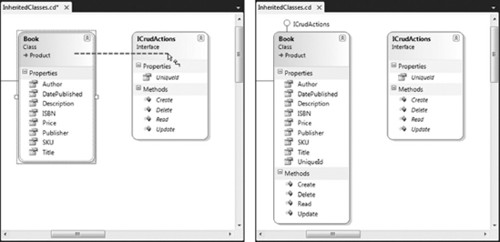
The Inheritance connector can be used in one more way that results in automatic code generation. In Figure 10-8 (left) an interface, ICrudActions, has been added to the diagram. When the Inheritance connector is dragged from a class to the interface, all the members of the interface are implemented on the class, as shown in Figure 10-8 (right).
The following code shows the code that is automatically generated when the ICrudActions interface is added to the Book class.
C#
#region ICrudActions Members
    public Guid UniqueId
    {
        get
        {
            throw new NotImplementedException();
        }
        set
        {
            throw new NotImplementedException();
        }
    }
public void Create()
{
throw new NotImplementedException();
}
public void Update()
{
throw new NotImplementedException();
}
public void Read()
{
throw new NotImplementedException();
}
public void Delete()
{
throw new NotImplementedException();
}
#endregion#Region ICrudActions Members
Public Property UniqueId As Guid
Get
throw new NotImplementedException()
End Get
Set
throw new NotImplementedException()
End Set
End Property
Public Sub Create()
throw new NotImplementedException()
End Sub
Public Sub Update()
throw new NotImplementedException()
End Sub
Public Sub Read()
throw new NotImplementedException()
End Sub
Public Sub Delete()
throw new NotImplementedException()
End Sub
#End RegionThe rest of the code generation functions in the Class Designer are available under the somewhat unintuitively named IntelliSense submenu. Because these code generation functions apply only to classes, this menu is visible only when a class or abstract class has been selected on the diagram. The two code generation functions included on this menu are Implement Abstract Class and Override Members.
The Implement Abstract Class function ensures that all abstract members from the base class are implemented in the inheriting class. To access this function, right-click the inheriting class, choose IntelliSense, and then choose Implement Abstract Class.
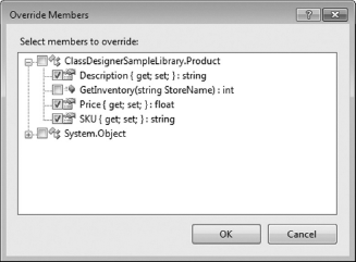
Somewhat related is the Override Members function, which is used to select public properties or methods from a base class that you would like to override. To access this function, right-click the inheriting class, choose IntelliSense, and then choose Override Members. The dialog box shown in Figure 10-9 is displayed, populated with the base classes and any properties or methods that have not already been overridden.
In Chapter 8 you saw how Visual Studio 2010 provides support for refactoring code from the code editor window. The Class Designer also exposes a number of these refactoring functions when working with entities on a class diagram.
The refactoring functions in the Class Designer are available by right-clicking an entity, or any of its members, and choosing an action from the Refactor submenu. The following refactoring functions are available:
Rename Types and Type Members: Allows you to rename a type or a member of a type on the class diagram or in the Properties window. Renaming a type or type member changes it in all code locations where the old name appeared. You can even ensure that the change is propagated to any comments or static strings.
Encapsulate Field: Enables you to quickly create a new property from an existing field, and then seamlessly update your code with references to the new property.
Reorder or Remove Parameters (C# only): Enables you to change the order of method parameters in types, or to remove a parameter from a method.
Extract Interface (C# only): You can extract the members of a type into a new interface. This function allows you to select only a subset of the members that you want to extract into the new interface.
Note
You can also use the standard Windows Cut, Copy, and Paste actions to copy and move members between types.
Although the Class Designer is a very useful tool for designing and visualizing a class hierarchy, it can be cumbersome and unwieldy when trying to work with very large diagrams. To ease this burden you can either break up the diagram into multiple class diagrams, or install the Modeling Power Toys for Visual Studio 2010.
Modeling Power Toys is a free add-in to Visual Studio that extends the functionality of the Class Designer in several ways. It includes enhancements that enable you to work more effectively with large diagrams including panning and zooming, improved scrolling, and diagram search. It also provides functions that address some of the limitations of the Class Designer such as the ability to create nested types and new derived classes and display XML comments.
The add-in, including source code, is available from http://modeling.codeplex.com/. The download includes an MSI file for easy installation.
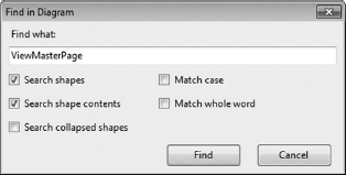
The Modeling Power Toys for Visual Studio 2010 provides some very useful enhancements for visualizing and working with large class diagrams. The diagram search feature is one of the more useful; it allows you to search the entities on a diagram for a specific search term. The search dialog, shown in Figure 10-10, is invoked via the standard Find menu item or Ctrl+F shortcut.
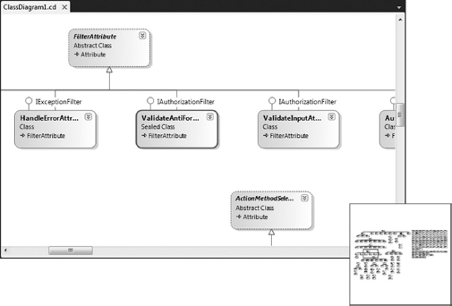
Another useful tool for large diagrams is the panning tool, which provides an easy way to see an overview of the entire diagram and navigate to different areas without changing the zoom level. You can invoke this tool by clicking a new icon that appears in the bottom right of the window, which displays the panning window, as shown in Figure 10-11.
The Modeling Power Toys also allows quite fine control over what is displayed on the diagram via the filtering options. These are available via the Class Diagram menu, and include:
Hide Inheritance Lines: Hides all inheritance lines in the selection.
Show All Inheritance Lines: Shows all hidden inheritance lines on the diagram.
Show All Public Associations: Shows all possible public associations on the diagram.
Show All Associations: Shows all possible associations on the diagram.
Show Associations As Members: Shows all association lines as members.
Hide Private: Hides all private members.
Hide Private and Internal: Hides all private and/or internal members.
Show Only Public: Hides all members except for public; all hidden public members are shown.
Show Only Public and Protected: Hides all members except for public and protected; hidden public and/or protected members are shown.
Show All Members: Shows all hidden members.
Modeling Power Toys includes a number of enhancements that address some of the functional limitations of the Class Designer. Though the Class Designer can display nested types, you cannot create them using the design surface.
This constraint is addressed by the Modeling Power Toys by enabling you to add nested types including classes, enumerations, structures, or delegates. You can also easily add several new member types, such as read-only properties and indexers.
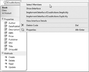
There are also some improvements around working with interfaces. Often it is difficult to understand what members of a class have been used to implement an interface. The Modeling Power Toys simplifies this by adding a Select Members menu item to the interface lollipop label on a type. For example, in Figure 10-12, the Select Members command is being invoked on the IStatus interface.
In addition to those mentioned here, many other minor enhancements and functionality improvements are provided by the Modeling Power Toys that add up to make it a very useful extension.
This chapter focused on the Class Designer, one of the best tools built into Visual Studio 2010 for generating and understanding code. The design surface and supporting toolbars and windows provide a rich user interface with which complex class hierarchies and associations can be modeled and designed.