
Chapter 14. Detection and Gestures
This chapter is going to be largely about one tool, OpenCV, and will be quite heavy on openFrameworks code. This is an important chapter because it is where you’ll learn how to turn the gestures and movements of a user, or other kinds of movement in an image, into meaningful input for an application. As anyone paying attention to the development of devices and the advancement of user interface and experience concepts over the past few years can tell you, this topic is one of the most interesting and important ideas in contemporary device design. Surfaces, tangible interaction devices, and free gesture interfaces have been incorporated in many different kinds of devices in the past few years.
Computer vision is a field of computing concerned with creating “seeing” applications by feeding an application a series of images, like a video, or a single image. Usually these images are analyzed for something in particular, such as looking for a light or for a face. Unlike human sight, a computer needs a good deal of instruction on what it should be looking for in an image. Computer vision techniques can be used to find fingertips, track gestures, find faces, or simply detect motion. Images are analyzed by looking for patterns in color values of the pixels. Those changes can be grouped into objects and tracked over multiple images, or they can be analyzed using statistical algorithms to determine how likely something is to represent a certain object like a face or other specific object.
This chapter talks about computer vision, recognition, and gestures together because one of the more interesting ways to create interaction using computer vision is to use gesture and recognition. This allows the user to input data into a program through an image given to the computer. Recognition is the detection of a particular kind of object in an image, a face, a hand, or a particular image. A gesture is a pattern of movement over time. You can use both of these with Processing or oF applications by using the OpenCV library for computer vision. Gestures recognition and face recognition are really a particular way of generalizing patterns from data, and in the case of computer vision, that data is image data. Any system trying to use gestural input needs to accurately distinguish one gesture from another, determine the extent of each gesture, and determine and communicate whether it is a gesture that communicates a range of input values or functions as a binary input.
Computer Vision
Computer vision (CV) is a massive and complex topic that ranges in the disciplines it draws from. Statistical analysis, physics, and signal processing all are important contributors to the development of computer vision techniques and libraries. Some of the most important arenas where computer vision is being used are robotics, surveillance machines, weapons systems, games, toys, and touchscreen interfaces. Computer vision allows interaction designers to do what seemed impossible: create interfaces from the movement of the human body, without a need for an interface that the user physically manipulates. For a long time, applying computer vision techniques to interactive applications was unrealistic because the techniques were too time- and processor-intensive to allow real-time interaction and provide feedback quickly enough. However, newer processors and better algorithms and techniques for image processing have made it possible to analyze images from a video feed in near real time.
Artists and engineers have used gesture recognition and computer vision since the pioneering work of Myron Krueger in the 1970s. Krueger often talked about an art that was fundamentally about interactivity, rather than art that used interactivity as a gimmick. He focused on the idea of the interaction being the medium of communication, just like language, text, and pages are to a book or canvas and paint are to a painting. His ideas and work are worth a look for designers and for artists alike because even in the 1960s and 1970s he had a clear vision of how to connect people and virtual spaces.
There are a few key areas of research in computer vision. Image processing and image analysis tend to focus on 2D images and deal with how to transform one image into another. Some techniques for altering images were covered in Chapter 10. Another area of computer vision research focuses on the 3D scene projected onto one or several images and deals with reconstructing the scene from one or several images. Machine vision is concerned with processing of image data to control a robot or other kind of machine. It’s most often concerned with inspection or measurement and focuses on precise calculations in controlled environments like factories. This gives the research and algorithms used by machine vision a slightly different bend than those used in analyzing uncontrolled situations where light changes quickly and unpredictably. Pattern recognition is another field that uses various methods to extract information from image data, looking for particular data that can represent a written letter or word, a fingerprint, or a kind of airplane, to give some common examples.
Computer vision generally, though not always, follows a particular sequence. First, the program needs to acquire the image through some process of digitalization. A digital image is produced by one or several image sensor that might be a light-sensitive camera, a range sensor, a radar, or an ultrasonic device. The pixel values typically correspond to light intensity in one or several spectral bands (gray images or color images) but can also be related to various physical measures, such as depth, absorption, reflectance of sonic or electromagnetic waves, or nuclear magnetic resonance. Next, the program will do some kind of preprocessing, specifically, resampling the image, reducing noise in the image, blurring it, increasing the contrast, or performing other kinds of changes. You’ll see this in the examples shown in this chapter; usually the images are converted to grayscale or blurred, or both, before being processed. Next, the program will look for features that it’s interested in—lines, edges, ridges, corners, blobs, or points. This is often called feature extraction. Finally, the program will perform high-level processing on a small part of the data that it’s actually interested in. For instance, in an application looking for faces, all things that could be faces are checked more closely to see whether they do or do not actually appear to be faces. In an application that finds a specific part of the body, an arm for instance, the actual processing of the shape of the arm will take place in this final step.
Interfaces Without Controls
One of the wonders of working with OpenCV and computer vision is that the physical interface can become optional. There is no requirement that the user touch anything. This dramatically frees you as the designer, allowing you to literally create an interface out of air. With the recent emphasis on lighter, more transparent, and more minimal interfaces using computer vision to capture user input seems thrilling. Before you get too excited by the concept, though, you need to consider the ramifications of that lack of interface. Interfaces are what they are because users require information about what information they can send, what might be done with the information that they send, and how that system to which they are sending the information will use the information.
Your messages to the user about what they are doing and how the system receives information about what they are doing becomes absolutely vital when making computer vision interfaces. You’ll want to avoid the vague “you do something, it does something back” mode of interaction. While this can be fun to experiment with and is an excellent way to learn about computer vision and test certain ideas, it doesn’t make for a particularly rich experience. One of the great realizations that started the flurry of touchscreen interfaces was the precise reactivity of the prototypes of Jeff Han’s Media Wall. These were touchscreens that reacted to user movements in real time and tracked fingertips and gestures with great precision, making the interaction both precise and natural. Once the touchscreen started to become an interactive surface that was not only dynamic but was precise as well, it became possible to develop new and different kinds of applications with them. Touchscreens had been around for a long time before 2004, but they were ATM screens or kiosks where the user touched a button much the same way as if they clicked a mouse. When working with purely gestural interfaces, it becomes even more important to ensure that the modes of input and the feedback to the user are precise, timely, and intelligible. How you go about doing that is entirely up to you.
Creating a gesture library, a set of specific gestures that your application will look for and react to, is important if you’re going to make an application that will use gestures, whether those gestures will be input into a touchscreen, will be in the air, or will be the movement of a body. Defining ahead of time what gestures your application will be looking for will make your decisions about how to structure your application and how to test it a great deal easier for you. With all the recent developments in touchscreens, there is an informal but growing library of recognized gestures: two fingers slide, pinch, tap to select, and so on. Dan Saffer wrote an excellent book called Designing Gestural Interfaces (O’Reilly) that details many of these gestures and what meaningful uses for them might be.
You should think about how to signal what a device is interpreting a gesture to be by providing either some textural feedback or some visual feedback. Many touchscreen devices draw a small white dot around the user’s finger so that the user can see where the application thinks their finger is located. A few other suggestions to think about include making an easy help gesture that users can call and making sure that users are given prompts. If you’re using gestures or specific actions, make sure you signal them clearly.
Example CV Projects
There are a wide range of projects that use motion tracking and computer vision techniques. The projects range from LaserTag, which tracks a laser pointer on a surface several meters away; to medical imaging, which helps detect cancerous tumors; to military applications; to projects like the NOR_/D Touchscreen that will be explored later in this chapter. This notion of the computer-mediated environment has percolated throughout the design, architectural, and artistic communities. Public artists like Greyworld make frequent use of computer vision. Pieces like The Monument to the Unknown Artist use the gestures of passersby to pose a robotic sculpture, relying on computer vision to determine the pose of the onlooker. Performance pieces like Messa di Voce by Golan Levin and Zachary Lieberman use computer vision to track the movements of a performer on a stage and particularly the motion of their heads. Computer vision is widely used in dance, in musical performance, and in video pieces in dance clubs to widen the physical space in a sense or to make a performer or a participant metaphorically “exist” in more than one place. Advertising or product demonstrations use computer vision to grab a viewer’s attention with graphics that mirror their movements. These computer vision techniques are becoming popular for video artists in dance clubs, as attention getters in shopping malls, in building lobbies, and on the street to attract attention for an advertisement, as well as being tools for artists.
Some of the most remarkable achievements in computer vision have been much more oriented toward engineering. In 2005 a race called the Grand Challenge was held where entrants equipped a car with a computer vision system to navigate desert terrain for several hours. Gary Bradski was a member of the winning team and used OpenCV in the vision system. Almost all robots and robotics applications have some element of computer vision to help them navigate terrain or analyze objects. Several companies are working with computer vision and gesture recognition to create gaming systems that operate without touch and without the need for a controller.
OpenCV
A team of developers at Intel headed by Gary Bradski started developing OpenCV in 1999. In 2007, Intel released version 1.0 as an open source project. Since it’s an open source library, it’s free to download, and you can use and modify it for your own purposes. Some of the core features that it provides are an interface to a camera, object detection and tracking, and face and gesture recognition. The library itself is written in C and is a little tricky to get started using right away without another library or framework to interface with it. Luckily, there are libraries that you can use with both Processing and oF.
ofxOpenCV is an add-on for openFrameworks that Stefan Hechenberger and Zachary Lieberman developed to let people working with oF use OpenCV easily in their projects. For Processing, both the OpenCV library—developed by Stephane Cousot and Douglas Edric Stanley—and the FaceDetect library utilize the OpenCV library. Because OpenCV is so massive, all the libraries implement a portion of its functionality. The ofxOpenCV library focuses on contour detection, as well as blob tracking and detection functionality. The Processing OpenCV library, as of the writing of this book, provides for real-time capture, image manipulation, and face and blob detection. The FaceDetect library for Processing is set up primarily to do face detection.
Using Blobs and Tracking
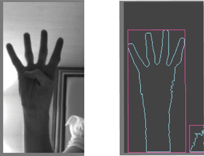
Movement tracking in OpenCV is done through what is commonly called a blob, which is a data object that represents a contiguous area of a frame. Blobs can be all sorts of different things: hands, faces, a flashlight, a ball. Blobs are usually identified by the contrast caused by the difference between adjoining pixels. This is quite similar to how edge detection, which you saw in Chapter 9, is done. A group of adjoining pixels that have the same relationship to another group of adjoining pixels, such as an area of darker pixels that is bordered by an area of whiter pixels, usually indicates a specific object (Figure 14-1).
Behind all the ethereal magic of gestural interfaces, particularly in using multiple tracking points, is the notion of a blob and of tracking. Tracking is the process of identifying one or more objects that display consistent movement within the field of the computer’s vision and identifying those objects over time. A hand is an excellent and commonly used example. A finger pressed on a surface that is light reactive is another commonly used concept in many surface-based interfaces. Colored objects, particularly those with a specific design that can be recognized by a computer vision system like those used in tangible interfaces, are another common interface concept that makes use of the tracking of blobs. Once a blob has been found, let’s say a hand against a white wall, the next step is to track its movement over time and ensure that the blob’s position is consistently updated to reflect the movement of the object throughout the images. This is what allows the movement of a single object in a visual field to be turned into a gesture, that is, a movement over time. This is substantially easier when you’re dealing with a single object, but when dealing with multiple blobs, it becomes mathematically and computationally more complex. The tracking of blobs is one of the difficult tasks in gestural interfaces that OpenCV makes a great deal easier. Later in this chapter you’ll learn how to track fingers in a controlled environment as well as learn how to use two different simple gesture recognition libraries, one for Processing and one for oF.
Starting with ofxOpenCV
ofxOpenCV is an add-on, but it’s included with the “fat
distribution,” the full distribution containing all of the add-ons,
so you won’t need to download it separately. Take a look in the
add-ons directory of your oF folder, and see whether the ofxOpenCV
folder is there. If so, you don’t need to do anything. If you don’t
find it, you might need to download it from http://addons.openframeworks.cc or grab a different
version of the oF download. As with other add-ons for oF, you’ll
need to include the main file for the add-on in an include statement:
include "ofxOpenCv.h"
Once you’ve done that, you should be ready to go. You may want to run the sample application that comes with the ofxOpenCv add-on.
One of the most important aspects of this add-on is its
contour finding capability. This is handled through the ofxContourFinder class that performs the
blob finding and tracking
task. In the .h file of your
application, define an instance of the ofxCvContourFinder
class:
ofxCvContourFinder contourFinder;
You’ll see more about how to use this method in the following
example, but for the moment, since this is one of the two key
methods of ofxCvContourFinder,
you should understand how the findContours() method works. Here is the
signature followed by a description of the parameters:
virtual int  findContours( ofxCvGrayscaleImage& input, int minArea,
int maxArea, int nConsidered, bool bFindHoles, bool bUseApproximation = true);inputThis is an
ofxCvGrayscaleImagereference (this is writtenofxCvGrayscaleImage&) to a grayscale image that will be searched for blobs. Note that grayscale images only are considered. So if you’re using a color image, you’ll need to highlight the particular color that you’re looking for beforehand. You can do this by looping through the pixels and changing the color values of any pixel with the desired color to white or black, for instance.minAreaThis is the smallest potential blob size as measured in pixels that will be considered as a blob for the application.
maxAreaThis is the largest potential blob size as measured in pixels that will be considered as a blob for the application.
nConsideredThis is the maximum number of blobs to consider. This is an important parameter to get right, because you can save yourself a lot of processing time and possibly speed up the performance of your application by pruning this number down. An interface that uses a user’s fingers, for instance, needs to look only for 5 points, one for each finger. One that uses a user’s hands needs to look only for two points.
bFindHolesThis tells the contour finder to try to determine whether there are holes within any blob detected. This is computationally expensive but sometimes necessary.
bUseApproximationThis tells the contour finder to use approximation and to set the minimum number of points needed to represent a certain blob; for instance, a straight line would be represented by only two points if
bUseApproximationis set totrue.
Once you’ve detected the blobs in an image, there are two
useful properties of ofxContourFinder that you’ll use
to determine what has been found in the contour finding:
blobsThe vector
ofxCvBlobblobs returns each blob that was found in the image. These should, if all has gone well, correlate to the blobs in previous examples so that you can begin to perform gesture detection.nBlobsThis is an int that returns the number of blobs found by the contour finder.
Commonly after contour detection, you’ll want to use the
nBlobs variable to loop through
the blobs contained in the blobs vector:
for (int i = 0; i < contourFinder.nBlobs; i++){
    contourFinder.blobs[i].draw(360,540);
}
This merits a look at ofxCvBlobs. As mentioned earlier, a blob
defines an area identified by the OpenCV plug-in as being a
contiguous object in the scene. Here are some of the properties of
this class:
areaThis gives the size of the blob in pixels.
boundingRectThis is an
ofRectangleinstance that can be drawn to the screen and that shows the height and width of the blob. This can be helpful to determine large regions of interest, or it can lead to some inaccurate results depending on the shape of your object. For instance, a squarish shape will be well represented by a rectangle, whereas a long thin shape with an angle in the middle will not.centroidThis is an
ofPointinstance with its x and y positions set at the center of the boundaries of the blob.holeThis is a Boolean value that indicates whether the blob contains a whole. This is also dependent on whether the call to
findContours()inofxContourFinderhas thefindHolesparameter set totrue.ptsThis is a
vectorofofPointobjects that represent the contour of the blob. This is different from the bounding rectangle. It’s listing the different points around the edge of the blob. The bounding rectangle is a rectangle around the extreme points of the blob.nPtsThis is an int that represents the number of points that are contained within the contour.
void draw( float x, float y
              )
This method draws the blob to the screen with the upper-left corner located at the point specified by the x and y values.
When contourFinder detects
a contiguous contour, it stores the information about that region as
a blob. Later in this chapter you’ll use those blobs to track
objects over time. First, though, look at the code for reading the
contours of an image, detecting blobs, and drawing them to the
screen:
#ifndef _CTRS_APP
#define _CTRS_APP

#include "ofMain.h"
#include "ofxOpenCv.h"

class contoursApp : public ofBaseApp{

public:

    void setup();
    void update();
    void draw();

    void keyPressed  (int key);

    ofVideoGrabber vidGrabber;
    ofxCvColorImage colorImg;
The three ofxCvGrayscaleImage images are used
together to determine what has changed between the current frame and
the background. The grayImage is
used to convert the color image from the video into grayscale, and
the grayBg image stores an image
of the background. These two are then compared using the absDiff() method of the ofxCvGrayscaleImage object, which creates
a new image based on the differences between the current image and
the image of the background and stores it in the grayDiff image:
    ofxCvGrayscaleImage grayImage;
    ofxCvGrayscaleImage grayBg;
    ofxCvGrayscaleImage grayDiff;
ofxCvContourFinder is the
object that will detect the contours in the image, finding borders
of objects or shifts in color and light:
    ofxCvContourFinder contourFinder;
    int threshold;
    bool bLearnBackground;
};
#endif
Here’s the .cpp file:
#include "contoursApp.h"

void contoursApp::setup(){

        bLearnBackground = false;

    vidGrabber.setVerbose(true);
    vidGrabber.initGrabber(320,240);
Now, allocate memory for the array of pixels that the image will use to save the incoming pixel data:
    colorImg.allocate(320,240);
    grayImage.allocate(320,240);
    grayBg.allocate(320,240);
    grayDiff.allocate(320,240);
}

void contoursApp::update(){
    vidGrabber.grabFrame();
    //do we have a new frame?
    if (vidGrabber.isFrameNew()){
Now ofxCvColorImage has all
of its pixels set from the newest frame that the video camera has
captured. If you don’t have a camera attached to your computer when
you run this code, you can always use the ofVideoPlayer class to play back a video
to use in contourDetection:
        colorImg.setFromPixels(vidGrabber.getPixels(), 320,240);
        grayImage = colorImg; // convert our color image to a grayscale image
        if (bLearnBackground == true) {
            grayBg = grayImage; // update the background image
            bLearnBackground = false;
        }
Now, find the difference between the background and incoming image to look for changes in the two images:
grayDiff.absDiff(grayBg, grayImage);
To ensure that the grayDiff
image doesn’t contain too much noise, increase the contrast on it.
You might want to make this higher or lower depending on the
lighting situation in the video image:
grayDiff.threshold(20);
Here’s the call to the findContours() method. In this case, the
smallest blobs that contourFinder
is looking for are 10 pixels, and the largest are one tenth the size
of the screen. contourFinder is
looking for two blobs and for holes in those blobs:
        contourFinder.findContours(grayDiff, 10, (340*240)/4, 2, true);
    }
}

void contoursApp::draw(){
    colorImg.draw(0, 0, 32, 240);
    ofSetColor(0xffffff);
    ofRect(0, 0, 320, 240);
    ofSetColor(0x000000);
Now, loop through all the blobs that contourFinder has detected, and draw
them:
    for (int i = 0; i < contourFinder.nBlobs; i++){
        contourFinder.blobs[i].draw(0, 0);
    }
}
If the user hits a key, then set the learnBackground parameter to true, meaning that the background should
be captured again so the new images will be compared with the
correct background. This can be good to do if the light changes in a
room or if the camera moves. Otherwise, you’ll find too many false
matches in your image:
void contoursApp::keyPressed  (int key){
    bLearnBackground= true;
}
Now that you’ve seen the basics of detecting blobs, the next step is to track them over a period of time.
Tracking Blobs with ofxOpenCV
Now that you have an understanding of both how to work with
ofxOpenCV in oF and what blob tracking is, you can begin to look at
tracking blobs over time. Tracking a blob or a shape across a
surface is, at its core, a matter of comparing all the blobs found
in a scene with the blobs found in the previous frame of the scene.
Just as in the earlier ofxOpenCV examples, this can be done using
the ofxContourFinder class within
the application to detect the contours of the objects. The key
difference is that once a blob has been detected, then its data is
stored in a vector. On the next frame, when the update method of the
application is called, all the blobs are captured again and compared
with the previous blobs to see which blobs from the previous frame
best correspond to the blobs of the current frame. Figure 14-2 shows a single
blob being tracked over several frames.
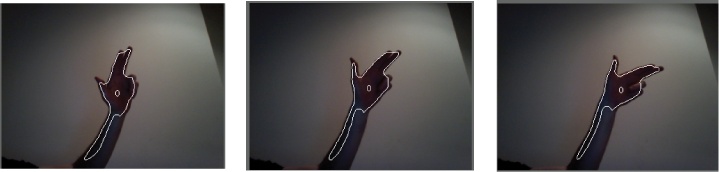
The 0 in the center of the blob indicates the position of the blob within the vector of discovered blobs. That 0 is drawn at the centroid, or center point of the blob. When looking through tracking code, you’ll often see references to the centroids of the blobs. This example makes the blob tracking easy because the object is in high contrast to its background and there is really only one object of interest in the frame. Generally, the more objects there are to track, the less accurate the blob tracking becomes, and the lower the contrast between objects. The more precise the control that you need over the tracking data, the more careful you’ll need to be when setting up your environment to ensure that the images have the proper contrast.
Here is the general algorithm for blob tracking:
Compare the the incoming image against the previous image by getting the different pixels between the two images.
Get the threshold of the image.
Find the contours of the thresholded image.
Compare the blobs from the previous image against the blobs from the current image to determine which blobs from the current image correlate reasonably well to blobs from the previous image. Then mark them as being the same object.
The first three steps are handled by an instance of contourFinder, and the fourth step is
handled by a new file, the ofxCVBlobTracker. This file is available
in the code downloads for this
chapter, so to conserve space, only the .h header file of the blob tracker is
shown here:
#ifndef oF_CV_BLOBTRACKER_H
#define oF_CV_BLOBTRACKER_H

#include <map>
#include <vector>
#include "ofMain.h"

#include "ofxCvTrackedBlob.h"
#include "ofxCvConstants_Track.h"

class ofxCvBlobTracker {
    public:
        vector<ofxCvTrackedBlob>  blobs;
        ofxCvBlobTracker();
        void trackBlobs( const vector<ofxCvBlob>& blobs );
Determine the order by which the present blobs came into existence:
int findOrder( int id );
The getById() method
returns a reference (note the & symbol) to the blob in the blobs
vector that has the ID passed to the method:
ofxCvTrackedBlob& getById( int id );
The draw() method draws all
the tracked blobs, drawing the contour of the detected blob and
drawing the ID number at its center:
void draw( float x, float y );
The blobs’ history, that is, all the tracked and detected blobs, is stored in the history vector, which is a vector of vectors. Each vector represents a capture of all the blobs from the screen, which are then compared to the newest blobs coming in to determine which ones most likely represent the same objects:
    protected:
        vector<vector<ofxCvTrackedBlob> > history;
You can find the .cpp
file of the ofxCvBlobTracker
class in the downloads for this chapter.
Now, take a look at ofBaseApp, which uses ofxCvBlobTracker to find and track blobs
in a live camera feed and draw them to the screen:
#include "ofMain.h"

#include "ofxCvBlobTracker.h"
#include "ofxCvTrackedBlob.h"
#include "ofxCvConstants_Track.h"

class trackerApp: public ofBaseApp {

    public:
        int cwidth;
        int cheight;
Here is the ofVideoGrabber
instance to capture video:
ofVideoGrabber vidGrabber;
As in the previous application, there are three images. The first stores bitmap data from the camera, the second is a grayscale image that will be thresholded to sharpen the contrast of the changed pixels, and the third stores the background for comparison against the incoming image:
        ofxCvColorImage  colorImg;
        ofxCvGrayscaleImage  grayImg;
        ofxCvGrayscaleImage  bgImg;
ofxCvBlobTracker doesn’t
actually capture the blobs; it simply stores blobs detected by the
ofxCvContourFinder instance and
compares them for similarities. In the .cpp file of the application, you’ll see
how they are used together:
    ofxCvContourFinder  contourFinder;
    ofxCvBlobTracker  blobTracker;

    int threshold;
    bool bLearnBackground;
};
Here is the trackerApp.cpp file:
#include "trackerApp.h"

void trackerApp::setup() {
    ofSetFrameRate( 60 );
    threshold = 60;
    bLearnBackground = true;
Start the videoGrabber, and
allocate memory for all the images:
    vidGrabber.initGrabber( 320, 240 );
    colorImg.allocate( 320, 240 );
    grayImg.allocate( 320, 240 );
    bgImg.allocate( 320, 240 );
Since the blobTracker is
set up to notify a listening application when detected blobs have
been moved, the tracker is set to notify this application. You do
this by passing the blobTracker
the this pointer so that it will
call the blobMoved(), blobOn(), and blobOff() methods of the
application:
    blobTracker.setListener( this );
}
In the application’s update() method, a new frame is grabbed
from the videoGrabber and
converted into a grayscale image:
void trackerApp::update() {
    ofBackground( 100, 100, 100 );
    vidGrabber.grabFrame();
    if( vidGrabber.isFrameNew() ) {
        colorImg = vidGrabber.getPixels();
The = here copies the color
pixels of the colorImg variable
into the ofxCvGrayscaleImage
after converting them to grayscale. This uses something called
operator overloading that allows different
operators, =, +, or –, for instance, to have different
meanings depending on the class. It’s too advanced a topic for this
book, but you can learn more about it in one of the more advanced
C++ texts listed in Chapter 18:
        grayImg = colorImg;
        if( bLearnBackground ) {
            bgImg = grayImg;
            bLearnBackground = false;
        }
        grayImg.absDiff( bgImg );
        grayImg.blur( 11 );
        grayImg.threshold( threshold );
contourFinder is passed the
grayscale image, and then the discovered blobs are passed to
ofxCvBlobTracker:
        contourFinder.findContours( grayImg, 50, 20000, 10, false, true);
        blobTracker.trackBlobs( contourFinder.blobs );
    }
}

void trackerApp::draw() {
    ofSetColor( 0xffffff );
    colorImg.draw( 20,200 );
    grayImg.draw( 360,200 );
This time, you draw from blobTracker so that all the blobs will be
drawn to the screen rather than all the detected contours as you did
in the previous example:
    blobTracker.draw( 20,200 );
  }
Taking a quick foray into virtual methods
The blob tracker can also work by using callback methods,
which the introductory chapters to Processing and oF discussed. A
callback is a method that is called in
response to a particular event like the mouseMoved() method in an oF application
or the keyPressed() method of a
Processing application. By creating a class that will call a main
application when an event occurs, you can save the processing time
needed to check a class again and again and simply call a method
on the main application to notify it that something has happened.
The downloads for this chapter contain a file called ofxCVTrackingConstants.h that
contains the following class declaration:
class ofxCvBlobListener {
    public:

        virtual void blobOn( int x, int y, int id, int order ) = 0;
        virtual void blobMoved( int x, int y, int id, int order ) = 0;
        virtual void blobOff( int x, int y, int id, int order ) = 0;

};
This declares some virtual methods that the class that extends this interface will have to override. The reasons for this may seem a bit confusing at first, but imagine an abstract representation of a person. We know that (in our little example at least) people will be able to speak, but we don’t really know what language they’ll be speaking. If we were to make a person class, though, we wouldn’t really want to include that kind of information, so we’d just assume that once we made some more concrete people, we’d figure out how they would speak. So, the person would look like this:
class Person {

public:
    virtual void speak() = 0; // here's the virtual method

};
This says, in essence, all people will need to speak, but you can’t make a person without extending this class and creating an overridden version of this method. For example, if you wanted to make a French person, they might look like this:
class FrenchPerson : public Person {
public:
    void speak() { printf(" Je parle Francais. "); }
};
whereas an Argentine person might look like this:
class ArgentinePerson : public Person {
public:
    void speak() { printf(" Hablo castellano "); }
};
Both override the speak()
method in their own ways, doing things that are particular to that
class. The virtual method simply sets a method that all classes
that extend it must override, thereby creating their own
versions.
Using the velocity of blobs
Let’s go back to the earlier example of the ofxCvBlobListener class. The ofBaseApp instance that your application
uses can extend multiple classes. Take a look at the class
declaration for the following application that declares two
different classes that it is extending:
class testApp : public ofBaseApp, public ofxCvBlobListener {This means that this class will have the three additional
methods of the ofxCvBlobListener class, in
addition to the methods of the ofBaseApp class. Adding those three
methods allows the blob tracking engine to notify the application
when a blob has moved and allows the application to react to it.
To do this, the application should use the blobMoved() method to get information
about the blob that has moved and use it. In the following
example, the movement of the blob is used to change the velocity
of two objects in different ways: using the movement of the blob
as a force upon a small circle drawn on the screen and using the
blob as an object that a ball can collide with. Chapter 9 introduced a simple sprite class
called Ball for drawing objects
that can be affected by vector forces. This example reuses that
class to draw the objects affected by the blob force:
#ifndef _TEST_APP
#define _TEST_APP

#include "ofMain.h"
#include "Ball.h"
#include "ofxVectorMath.h"
#include "ofxCvBlobTracker.h"
#include "ofxCvMain.h"

#define APP_WIDTH 1000
#define APP_HEIGHT 800

#define vid_width 640
#define vid_height 480
Notice that the ofBaseApp
extends ofxCvBlobListener so
that it will receive events from the blob tracker when they become
available:
class blobForceApp : public ofBaseApp, public ofxCvBlobListener {

public:

    void setup();
    void update();
    void draw();
Here are the two Ball
objects that will be used by the forces in the simulation. The
first instance will be affected by the hand that is detected and
tracked, and the second instance will be affected by the other
ball:
    Ball pushedBall;
    Ball physicsBall;

    int cwidth;
    int cheight;
    ofVideoGrabber  vidGrabber;
    ofxCvColorImage  colorImg;
    ofxCvGrayscaleImage  grayImg;
    ofxCvGrayscaleImage  bgImg;

    ofxCvContourFinder  contourFinder;
    ofxCvBlobTracker  blobTracker;

    int threshold;
    bool bLearnBackground;

    ofxVec3f blobCenter;
    bool checkCollision();

    void keyPressed( int key );
    void blobOn( int x, int y, int id, int order );
    void blobMoved( int x, int y, int id, int order );
    void blobOff( int x, int y, int id, int order );
These are the two vectors that will track the directions and
amount of force that should be applied to the two Ball objects:
    ofxVec3f gravityForce;
    ofxVec3f handForce;

};

#endif
Example 14-1 shows the .cpp file for the application:
#include "blobForceApp.h"

void blobForceApp::setup() {
    ofSetFrameRate( 60 );
    threshold = 60;

    blobCenter.x = 400;
    blobCenter.y = 500;
Initialize all the forces and objects:
    gravityForce = ofxVec3f(0.0, 1.0f, 0.0);
    handForce = ofxVec3f(0.0, 0.0f, 0.0);
    pushedBall.bounce = 0.8;
    pushedBall.maximum_velocity = 2;
    physicsBall.bounce = 0.8;
    physicsBall.maximum_velocity = 2;

    vidGrabber.initGrabber( vid_width, vid_height );
    colorImg.allocate( vid_width, vid_height );
    grayImg.allocate( vid_width, vid_height );
    bgImg.allocate( vid_width, vid_height );
    blobTracker.setListener( this );
}
The update() method grabs
the frame from the video, depending on the setting either from the
camera or from a video. If the frame is new, then continue
processing the image:
void blobForceApp::update() {

    bool bNewFrame = false;
    #ifdef _USE_LIVE_VIDEO
        vidGrabber.grabFrame();
        bNewFrame = vidGrabber.isFrameNew();
    #else
        vidPlayer.idleMovie();
        bNewFrame = vidPlayer.isFrameNew();
    #endif
    if( bNewFrame ) {
If you’re using live video, then set the color pixels from
the videoGrabber; otherwise,
set them from the vidPlayer:
        #ifdef _USE_LIVE_VIDEO
                colorImg.setFromPixels(vidGrabber.getPixels(), 320,240);
        #else
                colorImg.setFromPixels(vidPlayer.getPixels(), 320,240);
        #endif
Set the grayscale image from the colorImg:
        grayImg = colorImg;

        if( bLearnBakground ) {
            bgImg = grayImg;
            bLearnBakground = false;
        }
        grayImg.absDiff( bgImg );
        grayImg.blur( 11 );
        grayImg.threshold( threshold );
In this case, the application is looking for only one blob, the largest one. It will simply reject all the blobs it finds until it finds one that is the appropriate size. Depending on the relative position of the camera and where you’re tracking the blobs, you might want to make this different:
        contourFinder.findContours( grayImg, 200, 20000, 1, false, false );
        blobTracker.trackBlobs( contourFinder.blobs );
    }
Now, all the forces are added to the Ball instances:
    pushedBall.addForce(gravityForce);
    pushedBall.addForce(handForce);
    pushedBall.updateBall();
    physicsBall.addForce(gravityForce);
    physicsBall.updateBall();
Here, the force of the vector is reduced over time so that the results of actions are lessened over time:
    float tampedVal;
    float absVal;
    absVal = fabs(handForce.x);
    if(absVal > 0) {
If the value of the handForce is bigger than you want, you
can shrink it reasonably by taking the square root of the value.
This way, if it’s a value like 9 or 12, then it will very quickly
become a usable value, and if it’s a value like 3, it will reduce
more gradually:
        if(absVal > 2 ) {
            tampedVal = sqrt(absVal);
        } else {
            tampedVal = absVal - 0.1;
        }
        handForce.x = ( handForce.x > 0 ) ? tampedVal : −1 * tampedVal;
    }
    absVal = fabs(sqrt(handForce.y));
    if(absVal > 0) {
        if(absVal > 2 ) {
            tampedVal = sqrt(handForce.y);
        } else {
            tampedVal = absVal - 0.1;
        }
        handForce.y = ( handForce.y > 0 ) ? tampedVal : −1 * tampedVal;
    }
    if(    blobCenter.x == 0 && blobCenter.y == 0 ) { return; }
Here, the checkCollision() method looks to see
whether the blob, in this case, the user’s hand, has collided with
the Ball instance. If it has,
then determine what the result of the collision should be:
    if(checkCollision()) {
        physicsBall.collision(&blobTracker.blobs[0]);
    }
}

void blobForceApp::draw() {
    ofSetColor( 0xffffff );
    ofSetLineWidth(1);
    blobTracker.draw( 20,200 );
    pushedBall.drawFrame();
    physicsBall.drawFrame();
    ofSetColor( 0xffffff );
    ofSetLineWidth(3);
    ofLine(500, 400, 500+(handForce.x * 50), 400+(handForce.y * 50));
    ofCircle(500+(handForce.x * 50), 400+(handForce.y * 50), 10);
}
When the key is pressed, reset everything:
void testApp::keyPressed( int key ) {
        bLearnBackground = true;
        handForce.set(0.0, 0.0, 0.0);
        physicsBall.location.x = 400;
        physicsBall.location.y = 0;
}

void testApp::blobOn( int x, int y, int id, int order ) {}
Whenever a blob moves, the blob tracker calls the blobMoved() callback method to determine
the amount of force that should be set on the handForce vector variable:
void testApp::blobMoved( int x, int y, int id, int order) {
    ofxCvTrackedBlob b = blobTracker.getById(id);
    handForce.set(0.5 * b.deltaLoc.x, 0.5 * b.deltaLoc.y, 0.0);
    blobCenter.x = ( APP_WIDTH / vid_width ) * b.centroid.x;
    blobCenter.y = ( APP_HEIGHT / vid_height) * b.centroid.y;
}

void testApp::blobOff( int x, int y, int id, int order ) {}

bool testApp::checkCollision() {
    //difference vector of the 2 circles' positions
    ofxVec3f cDiff = physicsBall.location - blobCenter;
    float c = cDiff.dot( cDiff ) - 10000;
    if( c < 0 ) {
        return true;
    }
    return false;
}
This example is a very simple example of how to generate forces from computer vision and how to add forces to drawings. Of course, you can improve this example in a great number of ways or extend these basic techniques to create different kinds of reactivity, or different kinds of animations, from simple particle fields to games to water simulations.
Using OpenCV in Processing
So far in this chapter, you’ve looked only at OpenCV in oF
applications, but as mentioned earlier, there is an OpenCV library for
Processing as well. The OpenCV library is made accessible to your
Processing application through a class called OpenCV. First download the library from the
Processing website, and then move the library to the libraries folder of your Processing
installation. Import the libraries by calling the following import statement:
import hypermedia.video.*;
Create an instance of this class, and pass this reference to your application to the constructor; you’re ready to go:
OpenCV opencv;
opencv = new OpenCV(this);
To begin capturing video, call the capture() method, passing in the width and
height you want to capture. This automatically reads from the first
video camera attached to your computer.
int IMG_WIDTH = 400;
int IMG_HEIGHT = 300;
opencv.capture(IMG_WIDTH, IMG_HEIGHT);
To capture a frame of video, in each draw() method of your application you’ll
want to call the read() method of
the OpenCV library:
opencv.read();
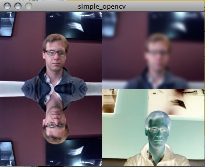
Here is a simple example that captures, flips, blurs, inverts, and then redisplays the captured image. The resulting images are shown in Figure 14-3.
import hypermedia.video.*;

// OpenCV instance
OpenCV opencv;
// blur value
int blurAmount = 17;

// image dimensions
int IMG_WIDTH  = 200;
int IMG_HEIGHT = 150;

int COLOR_SPACE = OpenCV.RGB;
//final int COLOR_SPACE = OpenCV.GRAY;

void setup() {

    size( IMG_WIDTH*2, IMG_HEIGHT*2 );

    opencv = new OpenCV(this);
    opencv.capture(IMG_WIDTH, IMG_HEIGHT);

}

void draw() {
    // grab image
    opencv.read();
Here, create a blur by calling the blur() method and passing the type of blur.
The options as of this writing are BLUR for a simple blur, MEDIAN, GAUSSIAN, or BLUR_NO_SCALE. Experiment with the different
options to see how they differ because they’re rather difficult to
describe in print:
opencv.blur( OpenCV.GAUSSIAN, blurAmount );
Now, draw the image to the screen:
image( opencv.image(), IMG_WIDTH, 0 );
The restore() method is
called to reload the original image data. This is quite important
because without calling this method, changes are applied sequentially.
For instance, if you comment out the following call to restore(), the inverted image will have the
blur applied to it. With the call to restore, the original image
captured by the camera is used again:
    opencv.restore( COLOR_SPACE );
    opencv.flip(OpenCV.FLIP_VERTICAL);
    image( opencv.image(), 0, IMG_HEIGHT);

    opencv.restore( COLOR_SPACE );
    opencv.invert();
    image( opencv.image(), IMG_WIDTH, IMG_HEIGHT);
Another way to draw the original image is to call the image() method of the OpenCV library and
pass OpenCV.SOURCE to it. This
returns the original pixels captured from the camera. In the following
line, these are passed to the image() method of the Processing application
to be drawn:
    image( opencv.image(OpenCV.SOURCE), 0, 0 );
}
Here, update the amount of blur when the mouse is dragged:
void mouseDragged() {
    blurAmount = (int) map(mouseX,0,width,0,255);
}
When the application is stopped, make sure to call the stop() method of the opencv instance:
public void stop() {
    opencv.stop();
    super.stop();
}
Now, let’s look at blob tracking using the OpenCV library. Like
the ofxOpenCV add-on, the Processing version of this library includes
a Blob class that used to define
the area of a tracked blob. The properties of this class should look
familiar to you if you read the previous section:
float areaThis is the area of the blob in pixels.
float lengthThis is the length of the perimeter in pixels.
Point centroidThis is the binary center of the blob.
Rectangle
            rectangle
This is a Processing
Rectangleinstance that contains the blob, defined by its boundaries.Point[] pointsThis is the list of points defining the shape of the blob.
boolean isHoleThis returns
trueif the blob is determined to be a hole inside of another blob.
To capture the blobs, simply call the opencv.blobs() method, passing the following
parameters:
blobs( int minArea, int maxArea, int maxBlobs, boolean findHoles )
In the following example, the image from the camera will be
captured and compared with a background image. One difference between
the oF add-on and the Processing library is that in Processing the
remember() method is used to save
the current image to memory. Once the image is saved, it can then be
accessed by using the opencv.image() method and passing OpenCV.MEMORY, as shown here:
opencv.image(OpenCV.MEMORY)
The difference between the image in memory and the current image from the camera will be used to find blobs in the image:
import hypermedia.video.*;
OpenCV opencv;
int w = 320;
int h = 240;
int threshold = 80;

boolean find=true;

void setup() {

    size( w*2+30, h*2+30 );
    opencv = new OpenCV( this );
    opencv.capture(w,h);
}

void draw() {
    background(0);
Read the latest image from the camera using the read() method. This saves the image into
memory so it can be accessed later:
    opencv.read();
    image( opencv.image(), 10, 10 );                // RGB image
    image( opencv.image(OpenCV.GRAY), 20+w, 10 );   // GRAY image
Each time the image is altered, the image in memory is updated,
allowing you to stack alterations to the image. The call to opencv.image(OpenCV.MEMORY) accesses the
image captured when the opencv.remember() method is called:
image( opencv.image(OpenCV.MEMORY), 10, 20+h ); // image in memory
Like in the previous oF examples, the difference of the
background image and the incoming image is used to determine what
pixels have changed between the two images. This is then drawn to the
screen using the image()
method:
    opencv.absDiff();
    opencv.threshold(threshold);
    image( opencv.image(OpenCV.GRAY), 20+w, 20+h ); // absolute difference image
Here, the blobs are detected in the image:
    Blob[] blobs = opencv.blobs( 100, w*h/3, 20, true );
    noFill();
    pushMatrix();
    translate(20+w,20+h);
Now, draw all of the blobs:
for( int i=0; i<blobs.length; i++ ) {The rectangle property of the
Blob class can be used to draw a
rectangle using the rect()
method:
        Rectangle bounding = blobs[i].rectangle;
        noFill();
        rect( bounding.x, bounding.y, bounding.width, bounding.height );
Now capture the rest of the properties of the blob:
        float area = blobs[i].area;
        float circumference = blobs[i].length;
        Point centroid = blobs[i].centroid;
        Point[] points = blobs[i].points;
        // centroid
        stroke(0,0,255);
Draw a small cross at the center of the blob:
        line( centroid.x-5, centroid.y, centroid.x+5, centroid.y );
        line( centroid.x, centroid.y-5, centroid.x, centroid.y+5 );
        fill(255,0,255,64);
        stroke(255,0,255);
Now, draw a simple shape to describe all the points of the blob:
        if ( points.length>0 ) {
            beginShape();
            for( int j=0; j<points.length; j++ ) {
                vertex( points[j].x, points[j].y );
            }
            endShape(CLOSE);
        }
    }
    popMatrix();
}
Listen for the spacebar being pressed to record a new background image:
void keyPressed() {
    if ( key==' ' ) opencv.remember();
}
Drag the mouse to change the threshold:
void mouseDragged() {
    threshold = int( map(mouseX,0,width,0,255) );
}

public void stop() {
    opencv.stop();
    super.stop();
}
Figure 14-4 shows this application running.

The Processing application is slightly more restrictive than the oF version because of how the core Java classes of the Processing version interact with the OpenCV core, but much of the basic functionality is available for you to use. Working with OpenCV in Processing is an excellent way to get started with computer vision and tracking.
Exploring Further in OpenCV
There are many other topics that you can explore in OpenCV that there isn’t space in this chapter to explain and explore properly. These are all used frequently and you can find more information on using them in Gary Bradskis OpenCV, in the OpenCV documentation, or on the oF forums at openframeworks.cc/forums.
- Line fitting
Line fitting is the process of examining an image to see whether it fits a certain line. A series of points can be “fitted” by examining the series and finding an equation that creates a line that fits those points. This is rather complex mathematically, but it has some very practical applications. For instance, using the change in the rate of change around a contour, you can determine whether a blob has a finger contained within it. Several examples are available on the oF forums that use this technique to find and track hands or fingers in a video feed.
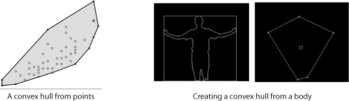
- Convex hulls
A convex hull is an object detection technique that attempts to determine the boundaries of an object given a set of points using an algorithm to determine the shortest distance between different points. Figure 14-5 shows an example.
Convex hulls are very useful for creating collision detection, For instance, you can use a convex hull to determine whether a virtual object has collided with an object detected in an image or a video. You can find examples of creating and using a convex hull in OpenCV on the oF forums.
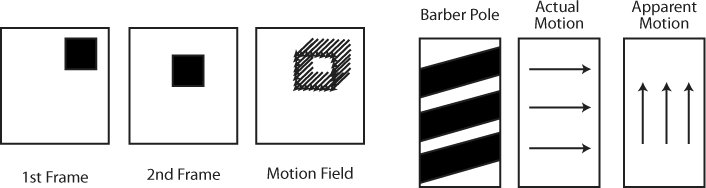
- Optical flow
Optical flow or optic flow is the pattern of apparent motion of objects, surfaces, and edges in a visual scene caused by the relative motion. It works by reading the apparent motion of brightness patterns in the image. Generally, optical flow corresponds to the motion field, but not always, as shown in Figure 14-6.
Usually apparent motion matches actual motion, which can be helpful for detecting motion where you don’t need to track blobs but simply want to detect movement. For instance, many reactive installations merely want to react to the general movement in front of the camera, not track blobs.
Detecting Gestures
You might have used a pen-driven interface at some point, and if you have, then you’re probably familiar with how it detects what character you’re trying to write when you input text. The characters are similar to the ones normally used but are simplified to reduce ambiguity for the program processing them. You might also be familiar with some other more complex gestures from other devices. Those sorts of gestures are best done with a single point of input, a pen, or a single finger, but they can be done with multiple points of input, though this is substantially more difficult. Often, gestures aren’t the best and easiest ways to get user input. In the case of writing, it’s far less efficient than typing on a keyboard. In some cases, though, they’re extremely effective and efficient ways for a user to input a simple command like clearing a grouping of photos, selecting an object or an area of an object, and doing some kinds of sign language recognition. The simplest way to detect gestures is by using a controller to act as an extension of the body so that the motion can be captured by software. Both mouse gestures and the Wii Remote work very well as gesture controllers. In this chapter, we’ll look at using the mouse for gesture detection so that you can easily examine the fundamentals of gesture detection.
Another object that works well for 2D gesture detection is a camera, as long as the environment is appropriate for using computer vision. An appropriate environment is bright and clear enough and has sufficient differentiation between the object of interest and the background. The object of interest can be a pen, a hand, or the user themselves.
To understand how gesture recognition is done, think about the gesture itself: a movement in a particular direction and with a certain pattern. Thinking about this in the way that a computational system could understand it, it would be a map of x, y, and possibly z points across a surface. This map is called a gesture map. These gesture maps are made by recording the vector of a movement to compare to all the gesture maps that the engine recognizes. Commonly, gesture recognition engines contain different algorithms to compare sets of movements to the gestures that they contain. One of the challenges of working with gestures is determining whether a gesture is complete. In the following examples, since the mouse is used as the gesturing instrument, the mouse button indicates the start and end of the gesture. In the case of a camera-based gesture, entering and leaving an area can indicate the beginning and end of a gesture, as can simply holding the tracked object still for a predetermined length of time.
Using ezGestures in Processing
One way to use gestures in a Processing application is to use
ezGestures, a gesture recognition library. It analyzes mouse or
Wiimote movements that you make while dragging the mouse or while
holding the A button of the Wiimote down. Then it compares the
motion against a gesture map that you’ve created for all the
gestures in which your application should be interested. It’s an
excellent way to experiment and prototype gestural applications. The
library understands four directions: UP, DOWN, LEFT, and RIGHT. Using these simple directions, the
application can recognize, for instance, the difference between a
circle and an L shape or the difference between
clockwise or counterclockwise gestures. It can’t, however, tell the
difference between a square and a circle or recognize diagonal
gestures, and it doesn’t pay attention to how large an area is being
covered, among other things.
There are two types of GestureListeners used in the ezGestures
library. In the first type, concurrent
listeners try to match the gesture to the pattern while the gesture
is still being performed. This means that a gesture can be
recognized and acted upon before the button is released. The second
type starts with Post; for instance, PostVShakeListener tries to match the
gesture to the pattern after the gesture is complete, which means
after the button is released. This is how the following example
works.
One thing to understand about the gesture detection library is
that it uses a regular expression to determine
what gesture is being drawn. A regular expression is really just a
way of making a pattern of letters. While they can be extremely
complex and difficult to read, they can be powerful tools. You don’t
need to understand too much about how they work to use the gesture
detection library. You’ll see a few strange symbols at the beginning
of the string that is passed to the PostGestureListener constructor method;
for instance, a circle is described as LDRU, or left, down, right, up. To make
sure that any and all circles are found in the messages that are
sent to the PostGestureListener
method, you’d use the caret (^)
to indicate that anything can come before the circle gesture and the
dollar sign ($), which is the
last thing in the string passed to the PostGestureListener. Here is an
example of creating a gesture listener that listens for a circle
gesture:
PostGestureListener pgl = new PostGestureListener(this, brain, "^(LDRU)$");
For each gesture that you want to listen for, you’ll need to
create a new PostGestureListener object that
will have the string that represents the gesture passed to it in the
constructor for that object:
import net.silentlycrashing.gestures.*;

GestureAnalyzer brain;
PostGestureListener boxListener;


void setup() {
    // initialize the gesture listeners
    size(500, 500);

    brain = new MouseGestureAnalyzer(this);
    brain.setVerbose(true);
    boxListener = new PostGestureListener(this, brain, "^(RDLU)$");
    boxListener.registerOnAction("drawBox", this);
}

void draw() {
    line(pmouseX, pmouseY, mouseX, mouseY);
}

void drawBox() {
    rect(mouseX, mouseY, 200, 200);
}
The previous example used PostGestureListener, but there are four
other classes that use concurrent gesture recognition:
ConcurrentHShakeListenerListens for a horizontal shake while the movement is being made
ConcurrentVShakeListenerListens for a vertical shake while the movement is being made
PostHShakeListenerListens for a horizontal shake while the movement is being made
PostVShakeListenerListens for a vertical shake while the movement is being made
In the following very simple example, the listeners will
listen concurrently; that is, they won’t wait for the gesture to be
finished. Instead, they’ll simply call their action method whenever
the gesture being listened for is heard. ConcurrentHShakeListener just listens for
a horizontal sweep back and forth, or in ezGestures terms RLRL or LRLR. In this simple application, drawing
the square gesture creates a new 3D box using the box() method, and the horizontal shake
clears all the boxes:
import net.silentlycrashing.gestures.*;
import net.silentlycrashing.gestures.preset.*;

GestureAnalyzer brain;
ConcurrentGestureListener boxListener;
ConcurrentHShakeListener shakeListener;

int numBoxes = 0;
SimplePoint[] boxes;

void setup() {
    // initialize the gesture listeners
    size(500, 500, P3D);
    lights();

   boxes = new SimplePoint[100];
As before, the MouseGestureAnalyzer is created and passed
a reference to the application itself:
    brain = new MouseGestureAnalyzer(this);
    brain.setVerbose(true);
ConcurrentGestureListener
is initialized and given the box string as its gesture to listen
for:
    boxListener = new ConcurrentGestureListener(this, brain, "(RDLU)$");
    boxListener.registerOnAction("createBox", this);
ConcurrentHShakeListener is
created and passed a reference to the MouseGestureAnalyzer instance.
Since the gesture that it’s listening for, the horizontal shake, is
already programmed, there’s no need to pass it another string to use
as its gesture:
    shakeListener = new ConcurrentHShakeListener(this, brain);
    shakeListener.registerOnAction("shakeHeard", this);
}

void draw() {
// line(pmouseX, pmouseY, mouseX, mouseY);
    background(122);
    int i;
Using the camera() method
as in Chapter 13, the camera is
positioned based on the user’s mouse position. This could, of
course, be the relative position of a Wiimote or another kind of
accelerometer connected to the computer via an Arduino:
    camera(0.0, mouseY, 0, // eyeX, eyeY, eyeZ
         width/2, height/2, 0.0, // centerX, centerY, centerZ
         0.0, 1.0, 0.0); // upX, upY, upZ
Here, the translate()
method sets the location where the box will be drawn, and the
s property of the SimplePoint is used to determine the size
of the box:
    for( i = 0; i<numBoxes; i++) {
       pushMatrix();
           translate(width/2 - 100, height/2 - 100, 0);
           translate(boxes[i].x, boxes[i].y, boxes[i].z);
           box(boxes[i].s);
       popMatrix();
    }
}

void createBox() {
    SimplePoint p = new SimplePoint();
    p.x = random(100);
    p.y = random(100);
    p.z = random(50);
    p.s = random(40);
    boxes[numBoxes] = p;
    numBoxes++;
}
When the horizontal shake gesture is heard, all the boxes will be cleared from the screen:
void shakeHeard() {
    println(" shaken ");
    numBoxes = 0;
}
This is a simple class to store the data about where the box should be drawn:
class SimplePoint {
    float x;
    float y;
    float s;
    float z;
}
One of the great advantages of the ezGestures library is that it works well with the Wiimote remote control. To help you work with the Wiimote, the ezGestures library has several different listeners that listen for buttons and actions specific to the Wiimote.
Using Gestures in oF
ofxSimpleGesture is an add-on for openFrameworks that lets you
do simple gesture recognition using either a mouse or a video
camera. To start, download the add-on from http://addons.openframeworks.cc. It’s loosely based
on an algorithm developed by Didier Brun and was originally written
in ActionScript for Flash Player. You can add your own custom shapes
to it or use a predefined alphabet. The ofxSimpleGesture plug-in has
a createStandardAlphabet() method
that creates the base alphabet using modified shapes that can easily
be recognized by the controller.
Figure 14-7 shows the shapes of each letter. The M, for instance, is broken into four separate gestures. As the user makes the shapes, the ofxSimpleGesture plug-in stores a record of the gestures and then attempts to determine what shape the user might be trying to make. The drawing that the user makes may be slightly different than the model for that gesture. The ofxSimpleGesture plug-in will take a best guess as to what the intended gesture is.
As you can see from the letter shapes shown on the left, the strokes to create the letters are simplified in a few cases to make it easier for the application to read the user’s gestures. You certainly don’t need to use these preprogrammed alphabetic gestures; you can easily create your own.

The ofxSimpleGesture requires that the application extend the
IGestureListener class, in
addition to the ofBaseApp class.
This means that the application has a new method, onGesture(), that can be called by the
ofxSimpleGesture plug-in when a gesture has been detected.
The declaration for an application using the ofxSimpleGesture might look like this:
#ifndef _TEST_APP
#define _TEST_APP
#include "ofMain.h"
#include "ofxGestures.h"

class gestureApp : public ofBaseApp, public IGestureListener {

    public:

        void setup();
        void update();
        void draw();

        void mouseDragged(int x, int y, int button);
        void mousePressed(int x, int y, int button);
        void mouseReleased();
Here’s the onGesture()
method that the ofxGestureRecognizer instance uses to tell
the application that it has detected a gesture:
void onGesture(const string& name);
Here’s the declaration of the ofxGestureRecognizer instance:
        ofxGestureRecognizer ofxg;
        string gesture;

    };

#endif
In the .cpp file of the
gestureApp, the ofxGestureRecognizer instance calls the
setListener() method to set the
callback methods of the application:
#include "gestureApp.h"

void gestureApp::setup(){
    ofBackground(255,255,255);
    ofxg.setListener(this);
The createStandardAlphabet() method creates
all the letters in the standard alphabet, as shown previously in
Figure 14-7:
    ofxg.createStandardAlphabet();
    gesture = "";
}

void gestureApp::update(){
    // nothing here
}

void gestureApp::draw(){
    ofBackground(255,255,255);
    ofSetColor(0x000000);
    ofDrawBitmapString(gesture, 100, 100);
}

void gestureApp::mouseDragged(int x, int y, int button){
    ofxg.addMousePosition(x, y);
}
Start the capture by calling the startCapture() method of the ofxSimpleGesture instance. This begins
logging all the user’s actions to determine the gesture:
void testApp::mousePressed(int x, int y, int button){
    ofxg.startCapture(x, y);
}
The gesture recording stops when the mouse is released:
void gestureApp::mouseReleased(){
    ofxg.endCapture();
}
Next is the callback method for the ofxGestureRecognizer that indicates to the
application that the gesture has been found:
void gestureApp::onGesture(const string& name) {
    gesture = "Your gesture was ";
    gesture += name;
}
Implementing Face Recognition
Face recognition doesn’t mean recognizing a person’s face; it means recognizing things that look like a face in an image. It’s accomplished by “training” a program to tell it what to look for in an image. The process of training applications to learn things is called machine learning and is a very interesting topic. In this section, you’ll learn about a specific machine learning technique. The most commonly used approach for face detection and recognition in OpenCV is based on a technique called the Haar Classifier. The Haar Classifier is a data file generated from a training process where an application is “taught” how to recognize something in different contexts. This can be things like recognizing whether a certain sound is a word being spoken by a user, whether a gesture is a certain shape, or, in this case, whether a pattern of pixels is a face. If you’re interested in learning more about Haar Classifiers and how machine languages work in OpenCV, once again refer to Gary Bradski’s and Adrian Kaehler’s book, Learning OpenCV (O’Reilly).
Creating a Haar Classifier is done by generating multiple images and setting the regions of interest in the image. This is usually called training, and Figure 14-8 shows some example images, generously donated by Todd Vanderlin.
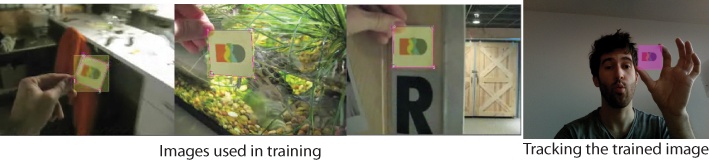
Notice how the three images to the left all show different variations of images containing the same object. After correct training, an OpenCV application can properly track the object in a video feed. Training and creating a Haar Classifier is beyond the scope of this book, but it’s helpful to understand roughly how the training works. In Figure 14-8, the training is for the small card image. The characteristics of that card, meaning the size, shapes, and shading of it, are encoded into an XML file that the OpenCV engine can read and compare to the contours of images that it is sent. In training faces, hundreds or thousands of images of faces are used to create a data model of what a face looks like, and then similar images of objects other than faces are used to create a data model of what a face does not look like.
One of the things that OpenCV generously provided to the open source community is a few sample trained XML files that represent a Haar Classifier that can be used in a few general situations. For instance, in the following example, the haarcascade_frontalface_alt_tree.xml file contains data about the characteristics of a face looking at the camera. Other files included in the OpenCV training files help detect faces seen in profile, full bodies, upper torsos, and lower torsos. In the downloads for this chapter, you’ll find the haarcascade_frontalface_alt_tree.xml file. If you open the XML file, you’ll see XML that defines information about the shapes that could potentially match the objects being defined. This XML file defines regions that contain certain attributes that are common to faces. If you’re curious what it looks like, open the file up and take a look.
You’ll want to make sure that you add the Haar training file to
the data folder of your application and the ofxCvHaarFinder.h and ofxCvHaarFinder.cpp files to your
application folder. The following application simply looks for faces
in the images coming from the camera and draws a red rectangle
wherever it detects a face using the ofxCvHaarFinder object:
#ifndef _HAAR_APP
#define _HAAR_APP

#include "ofxCvMain.h"
#include "ofMain.h"
Since the HaarFinder isn’t part of the ofxOpenCV add-on, you’ll need to include it separately in your application by including the .h file:
#include "ofxCvHaarFinder.h"

class haarApp : public ofBaseApp{

    public:

        void setup();
        void update();
        void draw();

        void keyPressed  (int key);
        ofVideoGrabber vidGrabber;
        ofxCvColorImage colorImg;

        ofxCvGrayscaleImage grayImage;
        ofxCvGrayscaleImage grayBg;
        ofxCvGrayscaleImage grayDiff;
As with the blob tracking example earlier in this chapter, the
images are read from the ofVideoGrabber instance and then converted
to grayscale images. This is then passed to ofxCvHaarFinder, which contains an instance
of the CvHaarClassifierCascade
object from the OpenCV library:
        ofxCvHaarFinder haarFinder;

        int threshold;
        bool bLearnBackground;
};

#endif
Here’s the haarApp.cpp file:
#include "haarApp.h"

void haarApp::setup(){
    vidGrabber.setVerbose(true);
    vidGrabber.initGrabber(320,240);

    colorImg.allocate(320,240);
    grayImage.allocate(320,240);
    bLearnBackground = true;
    threshold = 80;
Now, the XML file is loaded into ofxCvHaarFinder so that it can use that data
to analyze the images passed into it:
    haarFinder.setup("haarcascade_frontalface_default.xml");
}

void haarApp::update(){
    ofBackground(100,100,100);

    bool bNewFrame = false;
    vidGrabber.grabFrame();
    bNewFrame = vidGrabber.isFrameNew();
    if (bNewFrame){
            colorImg.setFromPixels(vidGrabber.getPixels(), 320,240);
            grayImage = colorImg;
        if (bLearnBackground == true){
            grayBg = grayImage;
            bLearnBackground = false;
        }
Now the image is passed to the ofxHaarFinder instance that will try to find
any objects that match the characteristics defined in the XML file
that was loaded:
        haarFinder.findHaarObjects(grayImage, 10, 99999999, 10);
    }
}

void haarApp::draw(){
The grayscale image is drawn, and then rectangles are drawn
where ofxHaarFinder has detected
faces:
    ofSetColor(0xffffff);
    grayImage.draw(20, 20);
ofxHaarFinder contains the
number of faces that it has discovered in the blobs vector. You can use the size() method of the blobs vector to create a loop to draw all
the detected faces:
    int numFaces = haarFinder.blobs.size();
    glPushMatrix();
    glTranslatef(20, 20, 0);
Loop through all the faces, and draw their bound rectangles:
    for(int i = 0; i < numFaces; i++){
        float x = haarFinder.blobs[i].boundingRect.x;
        float y = haarFinder.blobs[i].boundingRect.y;
        float w = haarFinder.blobs[i].boundingRect.width;
        float h = haarFinder.blobs[i].boundingRect.height;
        float cx = haarFinder.blobs[i].centroid.x;
        float cy = haarFinder.blobs[i].centroid.y;
        ofSetColor(0xFF0000);
        ofRect(x, y, w, h);
        ofSetColor(0xFFFFFF);
        ofDrawBitmapString("face "+ofToString(i), cx, cy);
    }
    glPopMatrix();
}
The keyPressed() method sets
the background and will be stored again so that incoming frames can be
compared to the backdrop of the image:
void haarApp::keyPressed (int key){
    bLearnBackground = true;
}
As shown in Todd Vanderlin’s example, anything can be trained for recognition, but since the OpenCV download comes with pretrained Haar files, it makes sense to demonstrate how to use them. Face tracking can be a very interesting way of providing responsiveness to an application. Since humans naturally tend to look at one another’s faces as an important source of information, the interactive possibilities of having an application that does the same are worth exploring. Golan Levin’s Opto-Isolator is an excellent example of an interactive art piece that uses face tracking, following the eyes of the viewer. Beyond face tracking, you can apply the same techniques to detect eyes, mouths, or noses, using the face recognition as a first pass and then determining within the face what shapes are most likely such as the eyes, mouth, and so on.
Exploring Touch Devices with oF
In 2007, the touch device was one of the most revolutionary concepts in interface design. Two years later, it has become remarkably commonplace for phones, computer screens, and interactive walls. Touchscreens have gone from being simple interfaces that allowed simple dragging to being complex user interface tools where users can enter text, draw, and perform many tasks with both hands that could previously be done only with a single mouse. There isn’t sufficient space in this book to cover the design and implementation of any of the touch devices, tools, or libraries that have been developed to help you in creating touch applications, but, as with so many things in this book, we’ll take a look at some of the projects that use similar techniques or tools as discussed in this chapter.
TouchKit
TouchKit, shown in Figure 14-9, is a modular multitouch development kit with the aim to make multitouch readily available in an open source fashion. TouchKit is comprised of software and a hardware component. The TouchKit team provides the source files and welcomes you to use, study, and appropriate the code and schematics for your work or projects. TouchKit is a plug-and-play solution for simple projects and an easily extendable base for experimental and cutting-edge endeavors.

You can find more information on NOR_/D and its projects at touchkit.nortd.com/. TouchKit will also be explored in greater detail in Chapter 16.
Tuio
Tuio is a protocol for tabletop tangible user interfaces that helps provide a common way to describe events. It’s used in a few different existing table interfaces like the reacTable, developed in Barcelona, and the tDesk, developed in Germany. It defines information about objects on a table surface, such as finger and hand gestures performed by the user or the movement of controller objects with fiducial markers like those shown in Figure 14-10.
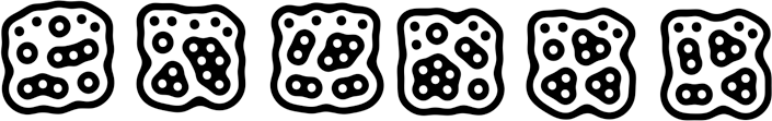
The Tuio protocol is implemented using the OpenSound Control (OSC) that was discussed in Chapter 12, and is usable on any platform supporting this protocol. There is an ofxTuio add-on available for oF that lets a table interact with an oF application. The Tuio library can be used with the Touchlib library for Processing or oF as well. You might want to look into some of the development efforts around the Tuio implementation if you’re interested in developing your own touchscreen devices.
Touchlib
Touchlib is another library that can be used to create multitouch interaction surfaces. It tracks blobs of infrared light and sends your information about these blobs as events. These events are named things like finger down, finger moved, and finger released. It includes a configuration application and a few demos to get you started. It will interface with most types of webcams and video capture devices. It currently works only under Windows, but it is being ported over to other platforms.
reacTIVision
reacTIVision is another open source computer vision framework. It can be used for tracking fiducial markers and for multitouch finger tracking in table-based tangible user interfaces (TUIs) and multitouch interactive surfaces. It is being developed by Martin Kaltenbrunner and Ross Bencina at the Music Technology Group at the Universitat Pompeu Fabra in Barcelona, Spain, as part of the reacTable project. reacTable is a novel electronic music instrument based using a tabletop multitouch tangible user interface. Martin Kaltenbrunner has created a library for working with reacTIVision that can be used for creating touchscreen applications using Processing.
What’s Next
If you’re really interested in using OpenCV, a great book to check out is Learning OpenCV by Gary Bradski and Adrian Kaehler (O’Reilly), one of the creators of OpenCV. It’ll teach you a great deal about how to use OpenCV to its fullest potential, which is something that this chapter has barely begun to do. The OpenCV manual, while not light reading, is available online as well as a free PDF download.
A number of online resources are available for people interested in working with computer vision and gesture tracking online; the oF forums are a particularly active place to get advice and ideas. The OpenCV project has its own mailing list and forum that might be an excellent resource for any one looking to troubleshoot a problem or come up with an idea for how a certain image could be processed. A great number of courses that use the OpenCV library or other image and motion processing libraries have materials online that you’ll be able to peruse.
The ARToolkit, developed at the University in Washington, is a library for developing augmented reality applications. Augmented reality (AR) is the process of placing computer graphics images onto live feeds from a camera and is a very interesting way of approaching creating an interactive application, since a representation of the world can be interwoven with computer synthesized images (Figure 14-11).
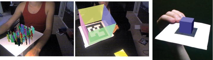
AR has been used in video tracking applications, children’s books, magic tricks, industrial applications, and many other areas. There are efforts underway to develop add-ons for oF that use the ARToolkit, and currently several examples in the oF forums are available for download that show how the ARToolkit can be integrated into an oF application.
Review
Computer vision is the use of algorithms that help identify certain patterns in bitmap images and track those objects over multiple frames. These can be used with live video from a camera or with video that has already been captured.
Tracking usually utilizes “blobs,” which are distinct areas within an image that the program identifies as being contiguous areas representing an object in the camera’s field of view.
Most tracking in openFrameworks is done using the OpenCV library and engine. The OpenCV project was initiated by Gary Bradski in 1999 and is a free and open source project computer vision library. It provides tools for tracking bobs, finding faces in images, and manipulating images among other things.
To use OpenCV in openFrameworks, use the ofxOpenCV add-on created by Zach Lieberman and Stephan. To use OpenCV in Processing, you can use the OpenCV library created by Douglas Edric Stanley.
The ofxOpenCV add-on allows you to create an instance of
ofxContourFinder to detect contours
in an image passed to the plug-in. This class has a findContours() method that can be passed a
grayscale image to detect contours as well as parameters to determine the maximum and minimum size
of blobs and the number of blobs that the contour finder should look
for in the image.
A virtual method is a method that is declared but not defined in
a base class that must be defined in any class that extends the base
class. This is often done to ensure that a class has a particular
method that can be called by another class, as in the case of the
ofxCvBlobListener class in this
chapter. Creating an application that extends ofxCvBlobListener requires that the
application can define the blobOn(), blobMoved(), and blobOff() methods that will be
called when the application detects blobs moving.
To use OpenCV in Processing, create an instance of the OpenCV
object in your application, and call its capture() method in the setup() method of your application. In the
draw() method of your application,
call the read() method of the
OpenCV object.
Blob detection using OpenCV in Processing is done using the
blobs() method of the OpenCV
library.
Gesture recognition is the process of checking the movement of an object, either the mouse or a finger gesture. Gesture recognition in Processing can be done using the ezGestures library. In oF, this can be done using the ofxSimpleGesture library.
Face detection can be done in OpenCV by using a Haar Classifier XML file that is loaded into the application at runtime. The example shown in this chapter uses a Haar file that has been set up to recognize faces that are looking directly at the camera. Other files are available for full body tracking or tracking the sides of faces. Haar files can also be trained to find many other types of shapes as well.
Many touch devices use computer vision and blob tracking to create multitouch interfaces, such as the reActivision project and the NOR_/D TouchScreen.
Tuio is protocol designed by Martin Kaltenbrunner that helps describe common properties of controller objects on the table surface as well as of finger and hand gestures performed by the user. For instance, the number of objects on a table, the movement of touches, rotation, and gestures can all be communicated between applications using Tuio.