
Chapter 17. Spaces and Environments
In this book, we’ve covered a lot of different means of getting input and creating feedback, but we haven’t discussed to a great extent where that feedback and input takes place. The location of the interaction is a very important consideration, because it provides context for that interaction. Using the user’s location as a data point is one thing; using the location as an element of the interaction itself is a different proposition. Sculptors, architects, and installation artists have explored the notion of communicating meaning through spatial relationships and architectural elements for many years.
You might want to sense data about an environment: reading the light in a room, listening to sound in a room, detecting motion in a room, or detecting gas with a sensor. This could mean making a smart environment or an enabled environment by allowing multiple devices in an environment to communicate with one another. It could also mean using space itself to communicate the message, as in the case of X10 communication, which sends messages over the electrical lines of a building. It could mean thinking sculpturally and helping design space that reacts to users’ commands, like making a room that is reconfigurable from a remote control or that changes based on the time of day, number of people in the room, or heat outside the room. There are so many different conceptions of space both in architectural senses and in aesthetic senses that it’s difficult to formulate any coherent meaning for how to approach space. In this chapter, the focus will be on technical strategies for using space in an interactive way that allows engagement.
Using Architecture and Space
One of the primary questions of architecture is “How do we think about space in a way that allows people to live, work, and play better in it?” This is not too dissimilar from the types of questions that you must ask yourself when designing an interface or control for a user, and in fact what many artists and designers have come to realize and explore is that space and structures are, in many ways, tools that shape what we can do and how we can do it.
In traditional architecture, the elements of a building are normally static and fixed at their time of construction. By using interactive design techniques and technologies, you can enhance and enable a building, making it transformable, reactive, and interactive. This is often called interactive architecture. The design approach of interactive architecture is different from traditional architecture because interactive architectural objects have behaviors and appearances that are molded together by the architect to create a reactive space and place. Creating successful architectural objects means designing their spatial characteristics and behavior in a way that fully opens up the possibilities of interaction with their environment. You can see hybrid uses of interactive architecture in product displays, trade show demonstrations, wall displays, sculptural pieces, installation pieces in galleries or museums that use multimedia equipment, and interior architecture.
Many techniques and ideas discussed elsewhere in this book are very relevant to how you might approach using space in your application. For instance, machinery can subtly change the nature of a room; for example, with a strong enough motor you could shift the location of a façade or wall, or with a very small electric motor you could raise or lower curtains. Artists and architects like Usman Haque, Jason and Zena Bruges, and Kas Oosterhuis, among others, have explored the overlap and potential of interactive and transformative architecture. Sound shapes a space in subtle ways as well: echoes, soft hums, and sound reverberations all change the nature of how we perceive a space. Lighting is of course vital, too, and a great number of both artists and architects are doing very interesting things with how lighting can transform spaces and objects; James Turrell, Pablo Valbuena, and H. C. Gilje have all used lighting and carefully controlled perceptual effects to sculpt spaces and re-create both rooms and outdoor areas.
Recent advances in materials for construction and fabrications mean that creating reactive environments is becoming easier and more affordable. Light-conductive materials and LEDs make lighting easier and more flexible, three-dimensional printing technologies mean that you can print plastic prototypes cheaply, and wireless controllers like the XBee mean that you can easily send information from one sensor to another without needing to run wires through a space. Interaction design is very rapidly becoming a valid way to approach design in the spaces in which people act.
Some excellent books are worth checking out if you’re interested in some of the thought around architecture and computing or interactive architecture. Digital Ground by Malcolm McCullough (MIT Press), Where the Action Is: The Foundations of Embodied Interaction by Paul Dourish(MIT Press), Digital by Design by Troika, and Responsive Environments by Lucy Bullivant (Victoria and Albert Museum) are just a few.
Sensing Environmental Data
You can detect change in an environment to create a response for a user in many different ways: detecting Bluetooth signals, heat, movement detected by ultrasonic sensors, computer vision techniques, weight sensors in a floor, the time of day, the amount of noise...the list is nearly endless. The idea of gathering ambient data about a space or an area and using that in an artwork or design object has been around for a long time. Audio artists have used ambient and environmental sound for a long time to create sound works. The techniques to create these works are vastly different and range from John Cage’s use of the sound of the audience in his piece 4’33 to Barry Truax’s Dominion to David Cunningham’s Listening Room.
The last 40 years have seen a steady architectural dialogue about how to shape environmental data to create a meaning or a particular sensation. The art and design collective Plaplax creates simple reactive spaces and spatial interfaces, children’s toys, and collaborations with dance companies, always working with both installation space and the body of movement of the user to create interaction. The group Random Internationals has created pieces like Audience, which has several hundred small mirrors attached to servos that track people as they walk past, creating a kaleidoscopic reactive mirror. What makes this approach to artwork different from what you’ll be reading about in this chapter is that in those works the processing of the environment data is done by the person in the space rather than by a device. The things that we can perceive in a space can be very different from the things that a device perceives in a space or an environment.
The data of your application will depend on the physical relationship that the user has to the space where the data is being gathered. It’s important to consider carefully how the data that you’re sensing in an environment is being used, whether you’ll make the user aware of what your system is detecting and what it will do with that data, how you’ll alert them to that, and how you’ll allow them to control the system.
On a more pragmatic level, what are the easily available data points for a space or environment? The temperature is one; the amount of ambient light in the room can tell you whether the lights are on or not, whether the room gets natural light, and whether it’s day or night. The color of light in a room is another one, especially if the space receives some natural light. Magnetic sensors can detect direction or a change in the location of magnetic elements in a space. Ultrasonic, infrared, and PIR motion sensors can all be used to detect movement; taken over time, this data indicates the amount of movement in a space as a whole or just as a detection that there is something in a particular part of a space.
Using an XBee with Arduino
To understand what the XBee is, we first have to talk about the ZigBee protocol. ZigBee is a standard for communicating over wireless networks that is designed to be inexpensive and not require a lot of power, making it perfect for small devices and ubiquitous computing. Its low cost means that you can deploy lots of devices cheaply to create a larger network, and its low power use means you can use small batteries and make devices run for longer periods of time. ZigBee is particularly well designed for mesh networks, which connect from node to node, rather than networks that are routed through a single router, like most wireless connections. Mesh networks are slower, but they also are set up to allow many devices to communicate with many other devices instead of assuming that all devices want to connect to the same single device. Mesh networks are very good at self-healing. That is, when one node goes down, the other nodes that are not down can redirect messages around that down controller. The goal of the ZigBee protocol is to have an inexpensive and general-purpose way to create mesh networks to use in many different settings. Just some of the applications where ZigBee can be used are the following: smart lighting, advanced temperature control, safety and security, movies and music, water sensors, power sensors, smoke and fire detectors, smart appliances, access sensors, industrial controls, and monitoring.
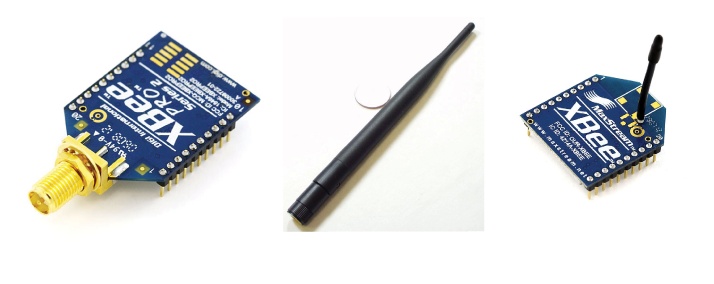
The XBee device is a ZigBee-enabled device commonly used with the Arduino. This means that there are numerous good tutorials by Tom Igoe and other member of the Arduino community; there are shields developed by Libelium; and if you’re working with the XBee controllers, you can count on being able to find someone in the Arduino community who can help you answer questions that you might have. Depending on the model, an XBee can communicate over distances up to 100 meters indoors. Using the XBee outdoors with line of sight between controllers, you can send and receive signals at a distance of up to 2 kilometers; if you use high-gain antennas, you can send signals up to 6 kilometers. You can use the XBee as a serial replacement, or you can put it into a command mode and configure it for a variety of broadcast and mesh networking options. You can do quite a number of things with such a small module. Figure 17-1 shows the different XBee options.
The XBee does have some limitations. The XBee 900 and XBee DigiMesh 900 transmit and receive at 900MHz and cannot communicate with the 2.4GHz frequency XBee controllers. Table 17-1 lists some information about the capabilities of specific models.
Name | Frequency | Type | Range (outdoor) | Notes |
XBee 802.15.4 | 2.4GHz | Point-multipoint | 100m (1.5km) | Antenna-ready. Compatible with Digimesh 2.4. |
XBee DigiMesh 2.4 | 2.4GHz | Mesh | 100m (1.5km) | Compatible with XBee 802.15.4. |
XBee Pro | 900MHz | Point-multipoint | 10km | Compatible with Digimesh 900. |
XBee DigiMesh Pro | 900MHz | Mesh | 10km | Compatible with XBee 900. |
XBee XSC Pro | 900MHz | Both | 25km | Compatible with DigiMesh Pro. |
XBee ZB | 2.4GHz | Mesh | 120m (1.5km) | Antenna-ready. |
Getting the XBee up and running can be a bit tricky. It requires a little configuration and the use of a terminal application, such as the command prompt on Windows or the Terminal application on OS X.
Note the circle on the jumpers for the XBee shield in Figure 17-2. These indicate whether the XBee will use the serial connection from the USB port of the Arduino or whether the Arduino controller itself will be using the serial port. If you’re not using a shield because you’re using an Arduino Mini or Pro, then you can use either the USB programmer to communicate with the XBee or an Arduino board with the processor removed, but it’s strongly recommended that you use a shield. You can find instructions for configuring the XBee without using a shield on the Arduino website, if you’re interested. In this book, though, we’ll be covering using the XBee shield.

The jumper on the shield, shown in Figure 17-3, sets the mode of the XBee shield. You set the shield to XBee mode to configure the XBee chip itself when you’re setting the baud rate for communication or setting the names of the controller. You set the shield to Arduino when you want to run the Arduino and have it communicate with the XBee shield.
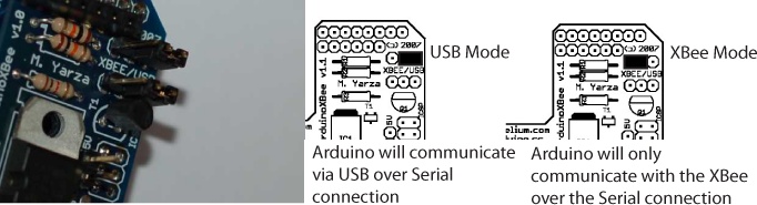
When the jumpers are in the XBee position, data sent from the microcontroller will be transmitted to the computer via USB as well as being sent wirelessly by the XBee module. The Arduino microcontroller will be able to receive data only from the XBee module, not over USB from a computer.
When the jumpers are in the USB position and the microcontroller is left in the Arduino board, the Arduino will be able to talk to the computer normally via USB, but neither the computer nor the microcontroller will be able to talk to the XBee module. If the microcontroller has been removed from the Arduino board, the XBee module can communicate directly with the computer. You’ll do this if you want to configure the XBee controller.
Creating a Simple Test
To upload an application to an Arduino board with an XBee
shield, the shield needs to have its jumpers set to USB. This means
ensuring that the two pins to the right of the jumper are connected,
rather than the two pins on the left of the jumper. Now you can
upload an application from the Arduino IDE as you normally would.
The XBee module on the shield is set up to work at 9600 baud by
default, so unless you reconfigure it, you’ll need to make sure
you’re passing 9600 to the Serial.begin() command in your sketch (as
shown in the following code). If your first Arduino doesn’t have an
LED on pin 13—that is, if it isn’t a Duemilanove—then connect an LED
to pin 13 and upload the following sketch (code). This sketch
reads a value sent over the XBee:
void setup() {
    Serial.begin(9600);
    pinMode(13, OUTPUT);
}

void loop() {
    if (Serial.available()) {
        byte val = Serial.read(); // this will read from the XBee
        if (val == 'X') {
            digitalWrite(13, HIGH);
        }
        if (val == '0') {
            digitalWrite(13, LOW);
        }
    }
}
Now unplug the first Arduino board from the computer, and switch the jumpers to XBee with the center pin and the pin farthest from the edge of the board connected. On the second Arduino controller, make sure the jumpers are in the USB setting, and upload the following sketch to the board. This sketch is sending data over XBee that the receiving sketch will read:
void setup() {
    Serial.begin(9600);
}

void loop() {
    Serial.print('X'),
    delay(1000);
    Serial.print('O'),
    delay(1000);
}
Turn off the serial monitor, and unplug the board. Switch the jumpers to the XBee setting. Now connect both boards to the computer to power them up. After a few seconds, you should see the LED on the first board running the receiving program turn on and off, once every second. This means that your Arduino boards are communicating wirelessly. Now you can power the Arduinos using 9V batteries, taking care to connect them correctly, and move them to different rooms in a house; you should see them continue to communicate.
The jumpers are important because when they’re set to USB, the
Arduino Serial print() and
println() methods will send and
receive information over the USB port. When the jumpers are set to
XBee, then those methods will send information over the XBee. The
read() method of the Serial works
the same way, so when the shield is set to XBee, you’ll find that
the Arduino will communicate only with the XBee and not with a
computer attached to it. This is important to keep in mind when
you’re working with the XBee shield: If things aren’t working, check
your jumpers first. You can also communicate directly with the XBee
shield from a computer by connecting it to an Arduino board whose
microcontroller has been removed and placing its jumpers in the USB
configuration. This works only with Arduino controllers that use the
Atmel 168 or 328 like the Duemilanove and Decimilia. With this
configuration, you can send data to and receive data from the XBee
module with any terminal program (such as the HyperTerminal in
Windows or the Terminal in Linux and OS X). This allows you to see
the data that the module is receiving from other XBee
shields.
Configuring the XBee Module
The XBee is in some ways like the Arduino itself in that it is programmable using commands. Table 17-2 lists some of the most commonly used commands.
Command | Description | Possible values | Default |
| The network | Between 0 and 65,535 or between 0x0 and 0xFFFF | 3332 or 0xD04 |
| The channel of the XBee module. | Between 0x0B and 0x1A | 0x0C |
| The address of the module. | Between 0 and 0xFFFF | 0 |
| The destination
address for the wireless communication ( | Between 0 and 0xFFFFFFFF | Starts at 0 |
| This restores the factory settings of the XBee. | N/A | N/A |
| This writes the parameter values to the memory of the XBee so that the next time it is powered up, the XBee will use its new settings. | N/A | N/A |
| This sets the baud rate that the shield will communicate at. | 0 (1200 bps) 1 (2400 bps) 2 (4800 bps) 3 (9600 bps) 4 (19200 bps) 5 (38400 bps) 6 (57600 bps) 7 (115200 bps) | 3 |
You can configure the XBee module with code running on the Arduino board or with software on the computer. To configure it from the Arduino board, you’ll need to have the jumpers in the XBee position. To configure it from the computer, you’ll need to have the jumpers in the USB configuration and have removed the microcontroller from your Arduino board.
You’ll need to follow a few steps to configure your XBee. If you’re using the Libelium shield, you’ll need to remove the processor from the Arduino module that the shield is connected to and then connect the Arduino to a computer. If you’re using the AdaFruit shield, then you simply need to connect the shield to the FTDI cable that comes with the shield. Now, you’re ready to get the module into configuration mode, which you can do in the Arduino IDE by sending three plus symbols (+++).
There’s one trick here: If you’re trying to configure the
module from the computer, you need to make sure your terminal
software is configured to send characters as you type them, without
waiting for you to press Enter. Otherwise, it will send the plus
signs immediately followed by a newline (that is, you won’t get the
needed one-second delay after the +++). Make sure that when you type
in the three +++ signs that you do it quickly; there can’t be more
than a second delay in between each +, or it won’t work correctly.
If you successfully enter configuration mode, the module will send
back the two characters OK.
Now, you’re in configuration mode, and you can begin sending
the commands listed in Table 17-2.
Note, though, that all those commands are prefaced by the letters
AT and that no space is placed
between the command and the value. For instance, to set the XBee to
use a baud rate of 19200 instead of 9600, you would type the
following:
ATBD19200
Then press Enter. The controller should respond with the
characters OK. Take note, though,
that if you change the baud rate, you’ll have to change the terminal
baud rate too, or the terminal won’t be able to communicate with the
XBee any longer. You may need to restart your terminal
controller.
You can also use the commands to query the controller. To get
the ID of the controller, send the ATID command without a value:
ATID
Then press Enter. The controller should respond with the
values 3332 (the default), unless
you’ve configured it to be something else.
It’s important to note that unless you tell the module to
write the changes to nonvolatile (long-term) memory, the changes
will be in effect only until you power off the module. To save the
changes permanently, use the ATWR
command followed by pressing Enter to which the module should
respond with OK.
To reset the module to the factory settings, use the ATRE command, and then save the changes
using ATWR. Note that like the
other commands, the reset won’t be saved into the module unless you
follow it with the ATWR
command.
You can also use multiple commands like so:
ATID3333,BD4,WR
This sets the ID and the baud rate and then saves it to the module.
Addressing in the XBee
The XBee uses a few different ways of addressing and finding objects in its network. There are three different kinds of values that can be used to define what can communicate with a particular XBee module and what other modules that XBee module will listen to messages from:
- Individual module addresses
Each XBee controller has an address that is set at the factory. You can also set the value of the
IDusing theDLandDHcommands. If a message is sent with a destinationID, the XBee whose address is this destinationIDwill hear the message.- Personal area network (PAN) IDs
This is another way that the XBee can be configured that has a coordinator sending out signals to any device using a particular PAN ID and one or more end devices, like a broadcaster and listeners. If a message is sent with a
PAN IDand that module has thatPAN IDset, then it will hear the message.- Channels
Any number of XBee modules can be set to use a certain channel, and that channel determines what messages the XBee module receives. If that module has the same channel as a message, then it will receive and process the message.
For two modules to communicate, they must be on the same channel, they must have the same PAN ID, and the destination address of the sender must match the address of the receiver.
Each XBee module has its own unique address, as well as a
destination address to which it sends its messages. The destination
address can specify a single destination, or it can be a broadcast
address, which will be received by all XBee modules within range.
The broadcast address is 65535
(0xFFFF in hexadecimal).
Now, this may seem a bit complex, but if you have only a couple modules, you’ll probably never need to change the PAN ID or channel. But if you’re in an environment with lots of modules, you might want to be sure that nobody else’s messages are getting mixed up with yours, so this offers a nice option to handle that.
If you’re on a Windows computer, then to configure your XBee controllers further, you’ll probably end up working with the XCTU terminal controller from Digi, available from www.digi.com/, to configure your controller. If you’re on Linux or OS X, you’ll open a terminal and type something like the following.
First, list the serial ports, and find the one you want:
$ ls -l /dev/tty.*
This is what I use, but what you need to type will depend on
the port you use. The following line of code opens a program called
screen and tells it to open the
USB port /dev/tty.usbserial-A9003QNn using 9600
baud:
$ screen /dev/tty.usbserial-A9003QNn 9600
Now enter command mode:
+++
Finally, get XBee firmware version; in screen, the ctrl-A b indicates a carriage return
indicating that the command is finished:
ATVR ctrl-A b
If you’re not using screen,
you won’t need to use the ctrl-A
b command.
A tutorial on XCTU is out of the scope of this book and far better documented on the Arduino forums and in Making Things Talk by Tom Igoe than I could do here, and the forums and Tom’s book are also substantially friendlier and easier to use.
So, what can you do now? Well, there are a few interesting ideas. If parts of a space can communicate with one another wirelessly, then opening a door could turn on the lights in the kitchen quite easily; power usage for a house could be monitored; blinds could be raised at a certain time to wake someone; and a single command could customize the temperature, lighting, and sound in a room for a particular user, all without running wires throughout the space. Health care, education, and business are all fields where ways to integrate responsive and intelligent architecture with the social activities, environmental concerns, and tasks in those fields are being explored in quite interesting ways. Another option is to simply synchronize machines or components throughout space, making the movements of one small robotic instrument match another, synchronize behavior across machines, or discover new machines as they are introduced to the environment. You can also synchronize data-gathering behavior across machines, creating simple networks that don’t require much power to communicate; sensors can communicate with a computer handling all the incoming data, and adjustments can be made to sensors.
Later in this chapter, you’ll look at an example of sending temperature data from multiple sensors to an Arduino linked to a home automation system.
XBee Library for Processing
Another option for working with the XBee and the Arduino is the XBee library for Processing that Rob Faludi, Daniel Shiffman, and Tom Igoe worked together to create. One of the difficulties in working with the XBee controller is parsing out the data from the messages sent by the XBee. By using Processing and the XBee library for Processing, you can parse out the data from a message quickly and easily. The following example assumes that you have two XBee modules that are sending messages to a receiver that is connected to a computer via a Serial connection. This means either having an Arduino with its chip removed, allowing it to communicate directly with the XBee, or alternatively using the following:
import processing.core.*;
import processing.serial.*;
import xbee.XBeeDataFrame;
import xbee.XBeeReader;
Here is a Serial port that will communicate with the XBee module:
Serial port;
An XBeeReader object will
read the data from the XBee module and put it in a friendly and
easy-to-read format:
    XBeeReader xbee;
    int[] analog;
    int[] digital;

    public void setup() {
        size(400, 400);
Remember that the XBee will be using the 9600 baud rate unless you change the settings of the module:
        port = new Serial(this, Serial.list()[0], 9600);
        xbee = new XBeeReader(this, port);
        xbee.startXBee();
        println("XBee Library version " + xbee.getVersion());
    }
Chapter 8 introduced the Processing
Serial library that allows a Processing application to read data
from the serial port of your computer. The XBee library works quite
similarly to the Serial library with an event handling function
called xBeeEvent(), which, like
the serialEvent() method of the
Serial library, is called for you when new data is available to be
read. Of course, the XBee library reads data only from the XBee and
not from the Serial, but the concept is the same:
    public void xBeeEvent(XBeeReader xbee) {
        println("Xbee Event!");
Next, grab a chunk of data from the XBee, often referred to as a frame:
XBeeDataFrame data = xbee.getXBeeReading();
The Processing library checks to make sure that the received data is in the correct series. The XBee library supports several different packet types, but each contains different data:
if (data.getApiID() == xbee.SERIES1_IOPACKET) {Now, we want to loop through all the data received in the frame and determine what data has arrived in the packet:
            int totalSamples = data.getTotalSamples();
            for (int n = 0; n < totalSamples; n++) {
                print("Sample: " + n + "  ");
                // Current state of each digital channel
                   //(-1 indicates channel is not configured)
                digital = data.getDigital(n);
                // Current state of each analog channel
                  //(-1 indicates channel is not configured);
                analog = data.getAnalog(n);

                for (int i = 0; i < digital.length; i++) {
                    print(digital[i] + " ");
                }

                for (int i = 0; i < analog.length; i++) {
                    print(analog[i] + " ");
                }

            }
        } else {
            println("Not I/O data: " + data.getApiID());
        }
    }

    public void draw() {
        background(0);
        fill(255);
Draw the data received in the last packet to the screen:
        for (int i = 0; i < digital.length; i++) {
           ellipse(50, i* 20, digital[i]);
        }
        for (int i = 0; i < analog.length; i++) {
           ellipse(250, i* 20, analog[i]);
        }
    }
Now that you see how to get data from the XBee, you’ll
probably want to send commands to it using the AT commands. The XBee library defines
methods to send most of the primary XBee commands for getting and
setting destinations and channels. To test some of the key AT commands, you can run the This method to respond to key presses when
the program window is active: These methods test a few of the
different AT commands:
public void keyPressed() {

    switch (key) {

    case '1':
        println(" Do node discovery and find any available nodes: ");
        xbee.nodeDiscover();
        break;
    case '2':
        println("Set the destination node of the XBees ");
        // this can be whatever you would like, just make sure that
        // there is a valid node first
        xbee.setDestinationNode("205");
        println();
        break;
    case '3':
        println("Get the Channel of the XBee using the CH command");
        xbee.getCH();
        break;
    case '4':
        println(" Send a datastring over the XBee ");
Here, the XBee will send a data string out using the address passed in. The two hexadecimal numbers that you see as the first two parameters are the high byte and low byte to send as the destination of the message. This way, an XBee can send a message with an address, and any other XBee can decide whether it wants to listen to the message. You can change these address values:
        xbee.sendDataString(0x0013A200, 0x403E17E6, "Bonjour!");
        break;
    case '5':
        println("Getting the high byte of the destination of the XBee");
        xbee.getDH();
        break;
    case '6':
        println("Getting the low byte of the destination of the XBee");
        xbee.getDL();
        break;
    case '7':
        println("Getting the ID of the XBee that sent data");
        xbee.getID();
        break;
    case '8':
        println("Get the Node Identifier using the NI command");
        xbee.getNI();
        break;
Another aspect of the XBee that we haven’t brought up yet is the ability of the XBee to write digital or PWM data out via one of its digital input or output pins:
    case '9':
        xbee.setIOPin(1, 5);
        break;
    case '0':
        xbee.setIOPin(1, 4);
        break;
    case '-':
        println("get the address of the XBee that sent data ");
        xbee.sendRemoteCommand(0x0013A200, 0x403E17E5,0xFFFE,"MY",-1);
        break;
    }
}
Paired with a Processing application, the XBee is a very powerful way to send commands remotely, across spaces such as a garden, field, or even, if you use a powerful enough XBee, across a small town, and easily integrate that with a Processing application. Of course, you can also use the XBee without connecting it to a Processing application. Paired with a relay like the RelaySquid or with a hand-built relay circuit as you saw in Chapter 11, the XBee can be used to control lights, appliances, or other large devices. It could also be used to set the values on a servo, drive a LCD display, or do anything else that an Arduino can do.
With some careful planning, you can use the node discovery capabilities of the XBee to create networks that configure themselves when new nodes are added or removed, with XBees on the network alerting other XBee controllers about the node’s capabilities are and what kind of information they expect.
Placing Objects in 2D
One of the more common tasks that you might find yourself wanting to do when working with a space is to locate objects in two dimensions. You might want to determine whether a person is in a room so that you can turn the lights on, whether someone is approaching a doorway, or whether an object has been moved to a certain location. Behind a lot of complex reactive effects is the simple determination of where a person is in a room or space so that changes can be made to the environment.
Before you get started placing objects in two dimensions, it’s important to know how to place them in one dimension—the distance between a sensor and an object in a straight line. Here’s a simple piece of code to do just that with an ultrasonic sensor like the ones discussed in Chapter 8:
unsigned long echo = 0;
Connect the PW pin on the ultrasonic sensor to pin 9 on the Arduino:
int ultraSoundSignal = 9;
unsigned long ultrasoundValue = 0;

void setup()
{
    Serial.begin(9600);
     pinMode(ultraSoundSignal,OUTPUT);
}

unsigned long ping(){
     pinMode(ultraSoundSignal, OUTPUT); // Switch signalpin to output
     digitalWrite(ultraSoundSignal, LOW); // Send low pulse
     delayMicroseconds(2); // Wait for 2 microseconds
     digitalWrite(ultraSoundSignal, HIGH); // Send high pulse
     delayMicroseconds(5); // Wait for 5 microseconds
     digitalWrite(ultraSoundSignal, LOW); // Holdoff
     pinMode(ultraSoundSignal, INPUT); // Switch signalpin to input
     digitalWrite(ultraSoundSignal, HIGH); // Turn on pullup resistor
     echo = pulseIn(ultraSoundSignal, HIGH); //Listen for echo
     ultrasoundValue = (echo / 58.138); //convert to centimeters
     return ultrasoundValue;
}

void loop()
{
     int x = 0;
     x = ping();
     Serial.println(x);
Next, delay the next ping by one-fourth of a second to make sure that the signals don’t interfere with one another:
    delay(250); //delay 1/4 seconds.
}
There are a few different strategies to place an object in space. This depends on what you are defining as “space.” You can always use a GPS for placing an object in geographical space, but it doesn’t help when placing an object in a room. Using a pair of cameras to position an object is an easy way to position an object in a room, but it requires that you have multiple cameras and that the cameras are connected to a computer that can handle multiple input streams from cameras. This is more a matter of picking the right camera and configuring your hardware than programming, but it is quite possible to do in an oF application. You can find more information on how to do this and what cameras would be best suited to your system on the oF forums and website.
To locate the object in a room, you’ll probably want to use a set of sensors, such as in Figure 17-4, that will provide enough data for you to triangulate the position of the object. You’ll need to determine the position of the object along at least two axes, usually the x and y. This presents a few problems, though, if you’re trying to track multiple objects through space or if the space that you’re interested in working with has multiple obstructions in it.

Using ultrasonic sensors in tandem presents a challenge: Numerous sensors often interfere with each other when placed within “hearing” distance of each other. This is because each sensor has no way of knowing which short pulse of sound came from which sensor and the data readings can get very unpredictable. The solution is to synchronize the sensors to prevent one sensor from listening while any other sensor is clicking. Infrared sensors present somewhat the same problem, except with light instead of sound; but they have an additional disadvantage: They cannot be easily sequenced, while the ultrasonic sensor manufactured by Maxbotix can.
To chain the Maxbotix ultrasonic sensors and have them to
operate in sequential daisy-chained fashion (as in Figure 17-5), you link the TX
pin of unit 1 to the RX pin of unit 2, and so on. The BW pin is
connected to +5 volts on each sensor. Then just set the pin connected
to the first sensor’s RX pin to HIGH, (shown in Figure 17-5 as pin 6), to
start the chain reading, and all of the sensors will read in sequence.
The analog values can then be read. In the example figure, you use one
pin to command the chain and three analog in pins to read the data
from the sensors.
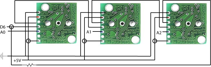
This chains the sensors together so that the values from each sensor will be sent to the analog pin 1. You’ll need to add a resistor between the last sensor’s TX pin back to the RX pin of the first unit through a 1K resistor.
Now you can begin reading them in sequence. In your setup() method, you want to have a delay of
250 milliseconds after powering on the sensors to give them time to
boot up. Each time you want to read the ring of sensors, you have to
“kick start” them by setting the RX pin HIGH on the first sensor for 20
microseconds. Now all of the sensors in the chain will run in
sequence. This “ring of sensors” will cycle around and around,
constantly maintaining the validity of their analog values. You can
then read the latest range reading at any time. This is the easiest
way to use them. After setting the pin on the Arduino connected to the
RX of the ultrasonic sensor to LOW,
you should wait 100 milliseconds for the sensor as it calibrates
itself. After that you can read the analog pin roughly every 50
milliseconds. The most recent range reading is always ready to be read
on the analog voltage pin, so once you start the chain and if you are
using it in continuous mode, you can read the values at any
time:
int ultraSoundSignalPins[] = {0,1,2}; // 3 Ultrasound signal pins
int ultraSoundTriggerPin = 6;        // output pin to start Ultrasound signals

void setup() {
    Serial.begin(9600);

    for(int i=0; i < 3; i++) {
        pinMode(ultraSoundSignalPins[i], INPUT); // Switch signalpin to input
    }
    pinMode(ultraSoundTriggerPin, OUTPUT); // set this pin to output
   //give the sensors time to boot up
    delay(250);
    // send RX pin high to signal to chain to ping
    digitalWrite(ultraSoundTriggerPin, HIGH);
    delayMicroseconds(20);
    digitalWrite(ultraSoundTriggerPin, LOW);
    pinMode(ultraSoundTriggerPin, INPUT); // electrically disconnects the pin
    delay(50);
}

void loop()
{
    unsigned long ultrasoundValue;
    unsigned long echo;
    delay(50);
    for(int i=0; i < 3; i++)
    {
Now the values from each sensor can be read:
        echo = analogRead(ultraSoundSignalPins[i]); //Listen for echo
        ultrasoundValue = (echo / 58.138);
    delay(50);
    }
}
The configuration shown in Figure 17-5 shows how multiple sensors could be configured. Setting them at the center of a room and reading them around from left to right is probably the easiest option since it allows you to determine the location of a reading very easily. Getting good coverage of a room requires quite a few sensors, though, and it can be less than optimal to put sensors in the middle of a room. Setting the sensors to read across from one another is perhaps more precise because it allows you to actually determine in two dimensions the location of an object, but it’s slightly trickier to put the values together and easier to get false readings if the sensors are not timed correctly or if there are multiple objects in the room. In either event, some planning ahead and experimentation will successfully let you determine the location of one or more people or objects in a room to a fair degree of accuracy.
Using the X10 Protocol
X10 is a protocol used to send digital data between devices over household electrical wiring. This means that you can send data around a house using the wiring a little like Internet cables are used for TCP or UDP communication. It works by sending a single digit over the wire every time the waveform of the current hits 0 in its cycle, called the zero crossing. This looks like the images in Figure 17-6.
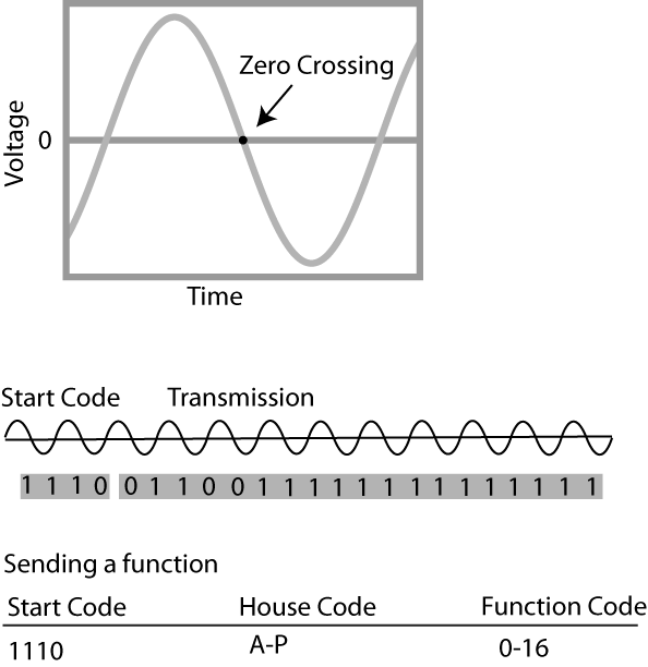
When the waveform is at 0, an X10 device can send a quick burst of data to any other connected X10 device. That data, once reassembled into a message, usually consists of an address and a command sent from a controller to a controlled device. That command could be telling the device to turn on or off or checking status, such as the dimming level of lights, the temperature in a room, the state of the coffee maker, or other sensor readings. Devices usually plug into the wall where a lamp, television, or other household appliance plugs in; however, some built-in controllers are also available for wall switches and ceiling fixtures.
The signal can’t pass through a power transformer or across the phases of a multiphase system, so more complex electrical systems might not work with X10 as expected. There are devices that will help you work around this, but for the purposes of this quick introduction, we’ll assume that you’re in a space with a single-phase system where you’re not attempting to cross any transformers. Most X10 modules fall into a few general types. Controllers send out an address and a command to control the receiver modules. Controllers do things like work as timers and interface with computers, telephone responders, universal transmitters, and alarm systems. Transceivers convert IR (infra red) or RF (radio frequency) signals to X10 signals, allowing you to easily set up controls using TV-style remote controls, wireless switches, motion detectors, and other means of wireless communication. There are also modules to control lights and equipment plug-in modules, built-in switches, micromodules, and modules for professional use.
The Arduino X10 library is built to send X10 commands through a unit that can be connected to the Arduino and provide access to a X10 network. The X10 protocol uses a few different constant values to send commands from one module to another module, and the Arduino X10 library includes constants that make working with these commands easier. The names of the constants should give you a good idea of what they’re supposed to do.
| | |
| | |
| | |
| | |
| | |
X10 also allows you to label and name different parts of an X10 circuit in a house, as well as naming different modules on each circuit, so that you can communicate with an individual module by name. To control specific devices, all modules are assigned an address, which consists of a House code and a Unit code. There are 16 House codes (A through P) and 16 Unit codes (1 through 16). Each House code has 16 Unit codes, so this means there are 256 possible addresses. House/Unit codes are referred to like this: A5, C7, M13, P4, and so on.
In this book, we’re most interested in using the Arduino with an X10 module, and that requires a module that the Arduino can interface with like the TW523, which is shown in Figure 17-7.
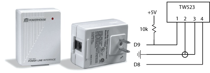
The TW323 X10 module can be connected to the Arduino as shown in the small schematic to the right in the figure. The Arduino X10 library will work with the PL513 one-way X10 controller and the TW523 two-way X10 controller. They simply provide a gateway into the X10 network that the Arduino can send signals to, much like a modem.
To make a simple application that writes an ALL_LIGHTS_ON message simply import the X10
library and call the constructor on the X10 object, passing the two
pins that you’ll be using for communication with the X10
module:
#include <x10.h>
#include <x10constants.h>
Call the constructor:
x10 myX10 = x10(8, 9);

int buttonPin = 5;
void setup() {
Set pin 8 to read input from the X10 controller and pin 9 to write to it:
    pinMode(8,INPUT);
    pinMode(9,OUTPUT);
    pinMode(buttonPin, INPUT);
    digitalWrite(buttonPin, HIGH); // turn on pull-up resistor
}

void loop() {
    int val = digitalRead(buttonPin);
    if(val == LOW) {
        // turn lights on if switch is pushed
        myX10.write(A, ALL_LIGHTS_ON, 1);
    }
    else {
        myX10.write(A, ALL_LIGHTS_OFF, 1);
    }
}
The possibilities that the X10 creates for you are in some ways similar to what the AC/DC switchers that you learned about in Chapter 7 enable, with a slight difference: X10 doesn’t simply control devices that use household current; it uses household current to communicate with devices. You can use a few ways to identify things of interest occurring in a specific space: RFID tags, motion sensors, and pressure sensors in a doorway.
In the next section, you’ll learn about RFID and see how to create an X10 network that sends signals when an RFID tag is read.
Setting Up an RFID Sensor
Radio Frequency Identification (RFID) is a technology that allows you to read and write to tags that can be read from a distance. RFID is used in credit cards, books, shipping containers of all sorts, and many other places. RFID is really a way to tag objects and physically port data. You can attach an RFID tag to any object to give it an ID, or if you are using an RFID writer, then you can both read and write to tags attached to an object.
Most RFID tags contain at least two parts. One is an integrated circuit for storing and processing information, modulating and demodulating an RF signal, and doing other specialized functions. The second is an antenna for receiving and transmitting the signal.
Some RFID readers can read tags from 6 meters away or more, but most have a short range of 5–10 centmeters. There are two kinds of RFID devices: readers and readers/writers. Devices that can write RFID data are generally more expensive. The frequency that a tag operates at is important because the reader and the tag need to be operating at the same frequency, for instance, 125Hz or 13.56MHz.
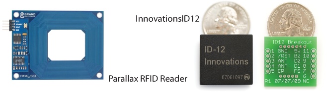
The Parallax RFID reader is a less expensive option for reading 125Hz RFID tags that has been used with the Arduino on many projects. Another Arduino-compatible option using the 125Hz tags is the Innovations ID-12 or ID-20 RFID readers. All of these can be powered from the Arduinos +5Vcc pin. Both the Parallax reader and the Innovations chips are shown, along with a breakout board for the ID-12 to make connecting it to your Arduino easier, in Figure 17-8.
If you’re interested in working with writing RFID tags, less expensive RFID reader/writers are available. As of the writing of this book, APSX makes 13.56MHz reader/writers available for less than $100 that have been used with the Arduino.
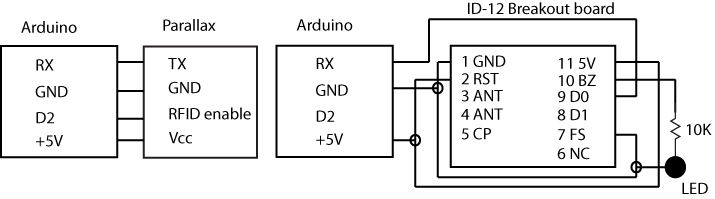
To connect the Parallax reader or the ID2 breakout board to the Arduino, follow the schematic in Figure 17-9.
Now you’re ready to read data from the RFID reader. In the case of the Parallax RFID reader, this operates only at a baud rate of 2400:
int  val = 0;
char code[10];
int bytesread = 0;

void setup() {
Start communication between the RFID reader and the Arduino at 2400:
   Serial.begin(2400);
   pinMode(2,OUTPUT); // connected to the RFID ENABLE
Digital pin 2 is connected to the RFID enable pin and sending it
LOW activates the RFID reader. If
you wanted for any reason to deactivate the RFID reader, you would
need to send it HIGH:.
    digitalWrite(2, LOW);
}

    void loop() {
        if(Serial.available() > 0) { // check if there's data
The beginning of RFID messages from the Parallax will contain a header, so you’ll know to continue reading the message. The Parallax RFID reader sends 10-digit tags, so you’ll know that after 10 values, you’ve read the entire tag. There is also a stop byte sent as 0x13 that is sent if the tag is complete, so the loop created checks for that value:
        if(Serial.read() == 10) { // look for a linebreak
            bytesread = 0;
            while(bytesread<10) { // read 10 digit code
                if( Serial.available() > 0) {
                    val = Serial.read();
                    if((val == 10)||(val == 13)) { // if header or stop bytes
                                                   // before the 10 digit
                                                        // reading
                        break;
                    }
                    code[bytesread] = val;
                    bytesread++;// ready to read next digit
                }
            }
            if(bytesread == 10) { // if 10 digit read is complete
                code(bytesread] = 0; // terminate the string
                Serial.print("RFID tags code is: ");
                Serial.println(code);
            }
            bytesread = 0;
            delay(500);
        }
    }
}
If you’re using the ID-12, the code is almost the same but with one exception: When checking the start and stop values for the ID-12, you’ll use 0x02 for the start and 0x03 for the stop, so in the previous code you’ll want to check for that value instead:
if(Serial.read() == 2) {
    // do the rest of the reading
You also could add some constants to define these values:
#define RFID_START 2  // Parallax start is 10, ID12 is 2
#define RFID_STOP 3    // Parallax stop is 13, ID12 is 3
One other thing to be aware of is that you’ll want to make sure that you disconnect the RX serial wire from the ID-12 when uploading the sketch.
Now that you understand the basics of RFID, you can combine it with other technologies. You can use Firmata library or serial communication to read and write RFID data from a tag and send it to Processing or oF applications, or an Arduino can use the RFID data directly. In the following example, you’ll combine RFID with X10 to turn the lights in a house on when the correct RFID tag is read. You could set this up near the front door of a house and turn your lights on simply by waving the tag in front of the reader.
This example uses one method that you probably have not seen
before: the strcmp() method. This
is a C method that is part of the standard C library, which means that
you can use it in an Arduino application, an oF application, or any
other C or C++ application. The method has this signature:
int strcmp(const char *s1, const char *s2);
The strcmp() method returns 0
if the strings are equal and a nonzero value if they are different.
You’ll get a positive value if the s1 is greater than the second and a negative
value if the s2 is greater. In this
example, that method is used to compare the RFID tag values to the
constant that we’re expecting. This example uses the following:
#include <x10.h>
#include <x10constants.h>
// RFID reader variables
#define TAG_LEN 12
#define RFID_START 2  // Parallax start is 10, ID12 is 2
#define RFID_STOP 3    // Parallax stop is 13, ID12 is 3
This is the value for the RFID tag that I’m using, but you’ll need to change it to the RFID tag that you have:
char tag[12] = { "0F03037185"};
char code[12];
int bytesread = 0;
int ledPin = 13; // Connect LED to pin 13
int rfidPin = 2; // RFID enable pin connected to digital pin 2
int val=0;
Now, add some variables for the X10 control:
int repeat = 1;
boolean lightsOn = false;

x10 house = x10(8, 9);

void setup() {
Now, begin serial communications with the RFID reader. The
SOUT pin of the RFID reader should
be connected to Serial RX (Digital Pin 1) at 2400 baud. If you want to
connect the RFID reader and a PC you can use the NewSoftSerial library
to set up communication between the RFID reader and the Arduino and
leave the hardware serial for computer to Arduino
communication:
    Serial.begin(2400);
    // X10 Module
    house.write(A, ALL_UNITS_OFF, repeat);
Set the pins that the X10 unit will use:
    pinMode(8,INPUT);
    pinMode(9,OUTPUT);
Set the pins that the RFID reader will use:
    pinMode(rfidPin,OUTPUT); // Set digital pin 2 as OUTPUT to connect it
                                // to the RFID /ENABLE pin
    pinMode(ledPin,OUTPUT); // Set ledPin to output
    digitalWrite(rfidPin, LOW); // Activate the RFID reader
}
void loop() {
This RFID-reading code assumes that the ID-12 is being used, but you just need to change the expected start and end values to use the Parallax RFID reader:
    if(Serial.available() > 0) {
        if((val = Serial.read()) == 2) {
            bytesread = 0;
            while(bytesread<10) {
                if( Serial.available() > 0) {
                    val = Serial.read();
                    if((val == RFID_START)||(val == RFID_STOP)) {
                        break;
                    }
                    code[bytesread] = val; // add the digit
                    bytesread++; // ready to read next digit
                }
            }

            if(bytesread >= 10)
            {
                Serial.flush(); // clear out the serial
                code(bytesread] = 0; // terminate the string
Use the strcmp() method to
figure out whether the string matches:
                if(strcmp(code, tag) == 0)
                {
If lights are off, turn them on, and if they’re off, turn them on:
                    if (lightsOn == false) {
                        house.write(A, UNIT_1, repeat);
                        house.write(A, ON, repeat);
                        lightsOn = true;
                    } else  {
                        house.write(A, UNIT_1, repeat);
                        house.write(A, OFF, repeat);
                        lightsOn = false;
                    }
After you’re done sending the X10 signal using the matched tag,
turn the RFID reader on and off and then flush() the serial port:
                    Serial.flush();
                    delay(1000); // prevent readings from the same tag.
                } else {
                    Serial.flush();
                    delay(1000);
                    Serial.flush();
                }
            }

            bytesread = 0; // clear system and prepare for next cycle
            delay(500); // wait
       }
    }
}
Now you have an application that communicates with an X10 network as well as reads RFID tags. There’s much more that you can do with an X10 network, but this should get you started with the basic controllers.
Reading Heat and Humidity
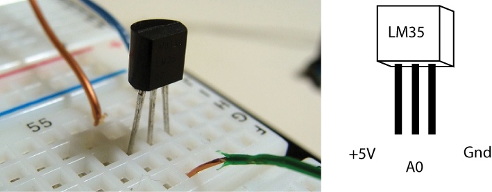
Another interesting and meaningful data point in an environment is temperature. Humidity and temperature are both fairly easy data points to read with an appropriate sensor, and they tell you a lot about a place or environment. Although you learned how to grab weather from online services in Chapter 12, there’s another way that provides more localized data: using a temperature sensor. We’ll look at two different sensors. First, the LM35 (Figure 17-10) is a heat detection chip that is inexpensive. It reads heat data and is quite easy to use. It’s accurate within about 1.5 degrees C at the limits of its ranges of –55C and 150C, and it’s accurate within about 0.5 degrees C between –25C and 100C.
The code to read the temperature is shown here and is based on some wonderful work by Daniel Andrade:
int pin = 0; // analog pin
int tempCelsius = 0, tempFahrenheit=0; // temperature variables
int samples[8]; // average of readings
int i;

void setup(){
    // this is where you'd start Serial communication if you want to use that
}
The data from the LM35 can be a little bit dirty, so it’s best to take several readings and average them. This adds the values received from the sensor together and then divides by the number of readings to ensure that any odd readings are averaged out:
void loop()
{

    for(i = 0;i< =7;i++){
        samples[i] = ( 5.0 * analogRead(pin) * 100.0) / 1024.0;
        tempc = tempc + samples[i]; // add the  eight samples together
        delay(1000);
    }

    tempc = tempc/8.0; // this is the average of the eight samples
    tempf = (tempc * 9)/ 5 + 32; // converts to fahrenheit

    delay(1000); // delay before loop
}
To read both heat and humidity, a company called Sensirion makes a sensor called the SHT15 that can be used to read both temperature and humidity anywhere. It connects to the Arduino using the I2C protocol, which was introduced in Chapter 8, using a pin to control the clock and another to read the data sent from the SHT15. The SHT15 uses two commands, one to read temperature and another to read the humidity, so when you send the appropriate command, the chip will respond with the correct data. The trick is that these commands need to be sent in binary, as in the following code:
int temperatureCommand  = B00000101;  // command used to read temperature
int humidityCommand = B00000011;  // command used to read humidity
Note the B in front of the binary numbers. This tells the compiler that you’re using a binary value to set the value of the integer. For the SHT15, the first three bits are the address, 000, and the last 5 bits are the command, so in the case of the temperature command, the actual command is 00101.
Next, declare the pins that will be used to communicate with the chip:
int clockPin = 2;  // clock
int dataPin  = 3;  // data
int error;  // to track whether any errors have occurred
float temperature;
float humidity;

void setup() {
Open the Serial port for communication with a listening computer. If you’re not sending the data to a computer, then you don’t need to do anything in this method:
    Serial.begin(9600); // open serial at 9600 bps
}

void loop() {
I’m a firm believer in the metric system, and so is the SHT15, so this application will read the temperature value from the chip and convert it to Centigrade. A conversion to Fahrenheit just requires changing the received value and was shown in the previous example:
    sendCommandSHT(temperatureCommand, dataPin, clockPin);
    waitForResultSHT(dataPin);
    int val = getData16SHT(dataPin, clockPin);
    skipCrcSHT(dataPin, clockPin);
    temperature = (float)val * 0.01 - 40;
    Serial.print("temperature: ");
    Serial.print((long)temperature, DEC);
    //Now we read the humidity
    sendCommandSHT(humidityCommand, dataPin, clockPin);
    waitForResultSHT(dataPin);
    val = getData16SHT(dataPin, clockPin);
    skipCrcSHT(dataPin, clockPin);
The relative humidity is calculated by taking the returned value and tweaking the value a bit to get a usable number that indicates the humidity in a percentage from 0 to 100:
    humidity = −4.0 +  (.0405 * val) + (-.0000028 * (val*val));

    Serial.print("humidity: ");
    Serial.print((long)humidity, DEC);

    delay(300000); // wait for 5 Minutes for next reading
}
This reads the values from the dataPin in between flashing the clockPin. Setting a pin HIGH and then LOW again is called
flashing and, in the shiftIn() method here, is used on the
clockPin to tell the SHT15 to send
the next bit of data:
    int shiftIn(int dataPin, int clockPin, int numBits) {
    int ret = 0;

    for (int i=0; i<numBits; ++i) {
        digitalWrite(clockPin, HIGH);
        ret = ret*2 + digitalRead(dataPin);
        digitalWrite(clockPin, LOW);
    }
    return(ret);
}
This method sends a command to the SHT15 sensor:
void sendCommandSHT(int command, int dataPin, int clockPin) {Set the mode on the pins and then flash both pins, setting them
HIGH and then LOW quickly, so that the chip knows that the
transmission is about to start. The clock pin is set HIGH and then LOW two times, and the data pin is set
HIGH, then LOW, and then back to HIGH. Now the SHT15 is ready to have data
shifted out to it:
    pinMode(dataPin, OUTPUT);
    pinMode(clockPin, OUTPUT);
    digitalWrite(dataPin, HIGH);
    digitalWrite(clockPin, HIGH);
    digitalWrite(dataPin, LOW);
    digitalWrite(clockPin, LOW);
    digitalWrite(clockPin, HIGH);
    digitalWrite(dataPin, HIGH);
    digitalWrite(clockPin, LOW);
As mentioned earlier, the commands have 3 bits in the address
section and 5 bits in the command section. This uses the shiftOut() command, which shifts out a byte
of data one bit at a time starting from either the most (left) or
least (right) significant bit. Each bit is written in turn to the
dataPin, after which the clockPin is toggled to indicate that the bit
is available. This is known as synchronous serial
protocol and is a common way that microcontrollers communicate with
sensors and with other microcontrollers. The advantage of using this
method of sending data is that the two devices always stay perfectly
synchronized and communicate at very high speeds. In this code, the
data is being sent with the most significant bit first. The third
parameter, MSBFIRST, is an Arduino-defined constant, which means
that the bit that determines whether a value is positive or negative
is sent first:
    shiftOut(dataPin, clockPin, MSBFIRST, command);

    // check for errors
   digitalWrite(clockPin, HIGH);
    pinMode(dataPin, INPUT);
    error = digitalRead(dataPin);
    if (error != LOW)
        Serial.println("got an error 0");
    digitalWrite(clockPin, LOW);
    error = digitalRead(dataPin);
    if (error != HIGH)
        Serial.println("got an error 1");
}
In this next code snippet, the waitForResultSHT() method waits for the
SHT15 to answer back by polling the data pin until it goes LOW. This is how the chip indicates to the
Arduino that it’s finished generating data and is ready to be read. If
the pin does not go LOW, after 1
second we can assume that there’s some sort of error with the chip and
the reading isn’t going to come back:
void waitForResultSHT(int dataPin) {

    pinMode(dataPin, INPUT);
    for(int i=0; i < 50; ++i) {
        delay(20);
        error = digitalRead(dataPin);
        if (error == LOW)
            break;
    }
    if (error == HIGH)
        Serial.println("got an error 2");
}
Getting data back from the SHT15 is a bit tricky. This next
example follows the example code
provided by Maurice Ribble and Hernando Berrigan to create and use a
shiftIn()
method, which more or less imitates how the Arduino shiftOut() method works except in
reverse:
int getData16SHT(int dataPin, int clockPin) {
    unsigned int val;

    // get the MSB (most significant bits)
    pinMode(dataPin, INPUT);
    pinMode(clockPin, OUTPUT);
    val = shiftIn(dataPin, clockPin, 8);
    val << 8;

    pinMode(dataPin, OUTPUT);
    digitalWrite(dataPin, HIGH);
   digitalWrite(dataPin, LOW);
    digitalWrite(clockPin, HIGH);
    digitalWrite(clockPin, LOW);

    // get the LSB (less significant bits)
    pinMode(dataPin, INPUT);
    val |= shiftIn(dataPin, clockPin, 8);
    return val;
}
The SHT15 sends Cyclical Redundancy Check data. We don’t need this data, so we want to tell the SHT15 that we don’t want it:
void skipCrcSHT(int dataPin, int clockPin) {
    pinMode(dataPin, OUTPUT);
    pinMode(clockPin, OUTPUT);
    digitalWrite(dataPin, HIGH);
    digitalWrite(clockPin, HIGH);
    digitalWrite(clockPin, LOW);
}
Now you can check the temperature and humidity for both inside and outside environments and use that data in your Arduino applications. You could use this for smart-home projects where the temperature of a house is adjusted according to the weather outside or a certain room is kept at a certain temperature. Connecting an SHT15 to an X10 system allows you to engineer quite sophisticated reactions to shifts in temperature or humidity. A few projects that become easier with temperature sensing include monitoring a wine cellar, detecting weather, or monitoring chemicals for photography.
There are other ways to sense temperature as well. There is a Lilypad-ready temperature sensing module; there is also a One Wire Digital Temperature Sensor with the product number DS18B20 that uses the 1wire protocol to sense temperature data. If you don’t need great precision, you can use very inexpensive 10k thermistors, a type of resistor that returns temperature values as voltage, that can return temperature data.
What’s Next
There are a great number more environmental sensors to explore. To read the amount of light in a room, you can use a light intensity sensor to determine how much light is shining on the sensor, or you can use a light color sensor to determine what color the light in a room is. Both of these can be quite useful for determining what’s happening or what factors are changing in a certain environment. Tutorials are available on the Arduino website for using the light color sensor. Another way to detect the color of light in an area is by using a chip like the PICAXE color sensor, which is very widely available online and gives you excellent readouts of light intensity and color.
You might want to look up the time in a location, which can be done using the DS1307 clock that returns the date and time without requiring that the Arduino run expensive calculations or that the Arduino always be connected to another computer.
If you’re interested in having control over lots of lights or other devices commonly used in staging, there is a whole series of devices that use the Digital MultipleXed (DMX) protocol for controlling projectors, LED lighting arrays, dimmers, lighting boards, and other devices. DMX is commonly used in theater or dance productions where a single operator needs to have control over a large number of devices and there are many sophisticated lights and projectors that can be controlled via DMX. The Arduino can use a driver chip like MAX485 or 75176 to talk to DMX enabled devices, sending and receiving DMX commands. There are several tutorials posted on the Arduino website that include code, wiring diagrams, and more technical information on the DMX protocol.
Review
ZigBee is a standard for communicating over wireless networks that is designed to be inexpensive and to not require a lot of power, making it perfect for small devices and ubiquitous computing.
Depending on the model, an XBee can communicate up to 100 meters indoors or outdoors within line of sight, a maximum of about 2 kilometers, and if you use of the high-gain antennas, you can send signals up to 6Km.
XBee controllers can be used for point-multipoint communication or for mesh networks.
There are several different types of XBee units. Different XBee modules are not always compatible, so make sure to either use the same type of module or check the compatibility.
AT commands are used to set the destination, ID, or other properties on an XBee and can be sent from the host computer or from an Arduino.
The XBee Processing library allows you to route information directly from an XBee to a Processing application and parse the information as well as send commands. It also helps you parse XBee data frames into all the respective parts.
Both ultrasonic and infrared sensors can be used to detect movement and the distance between an object and a sensor.
The Maxbotix ultrasonic sensor can be chained so that multiple sensors will read without causing interference with one another, which lets you use multiple sensors to place objects in two dimensions or to detect range over a larger part of a space or room.
X10 is a protocol used to send digital data between devices over household electrical wiring. The Arduino X10 library can be used to simplify sending and receiving data.
The X10 protocol can address different devices on a network and has specific commands to communicate with the system available.
RFID is a technology that can read tags that have a specific address written to them and send that information to an Arduino. There are also RFID writers that can write to a tag.
RFID tags are often 10-digit ASCII values that can be used to identify a tag, if you’re looking for a specific tag, you simply need to read the 10 digits from the Serial port and compare them to the value that you’re expecting.
You can read temperature using a device like the LM35 or a sensor like the SHT15 to read temperature and humidity data.