14
Graphics and Bit Manipulation
Problems involving graphics or bit operators are less common than those we’ve looked at so far but still appear frequently enough in interviews to merit discussion. Bit manipulation problems in particular often occur early in an interview as a warm-up to more challenging problems.
GRAPHICS
A computer screen consists of pixels arranged in a Cartesian coordinate system. This is commonly called a raster pixel display. Computer graphics algorithms change the colors of sets of pixels. Modern computers—even mobile phones—include specialized hardware-based high-performance implementations of graphics algorithms that are orders of magnitude faster than what can be implemented in software on the CPU. The challenge in real-world development is how best to use the graphics hardware; it would be extremely unusual to implement any of the techniques described in the following sections. Nevertheless, you may encounter problems involving the implementation of graphics algorithms both to test your understanding of computer graphics and to examine your ability to translate mathematical concepts into working code.
Often, the algorithm to generate a raster pixel image is based on a geometric equation. Because a computer screen has a finite number of pixels, translating from a geometric equation to a pixel display can be quite complex. Geometric equations usually have real-number (floating-point) solutions, but pixels are found only at fixed, regularly spaced locations. Therefore, every point calculated must be adjusted to pixel coordinates. This requires some kind of rounding, but rounding to the nearest pixel coordinate is not always the correct approach. You often need to round numbers in unusual ways or add error-correcting terms. When rounding is done carelessly, it often leads to gaps in what should be continuous lines. Take care to check your graphics algorithms for distortion or gaps due to poor rounding or error correction.
Consider something as simple as drawing a line segment. Suppose you try to implement a function that takes two endpoints and draws a line between them. After doing a little algebra, you could easily get an equation in the form of y = mx + b. Then, you could calculate y for a range of x values and draw the points making up the line. This function seems trivial.
The devil is in the details of this problem. First, you must account for vertical lines. In this case, m is infinity, so the simple procedure can’t draw the line. Similarly, imagine that the line is not vertical but close to vertical. For example, suppose that the horizontal distance spanned by the line was 2 pixels, but the vertical distance was 20 pixels. In this case, only 2 pixels would be drawn—not much of a line. To correct for this problem, you must rework your equation to x = (y – b) / m. Now, if the line is closer to vertical, you vary y and use this equation; if it is closer to horizontal, you use the original procedure.
Even this won’t solve all your problems. Suppose you need to draw a line with a slope of 1, for example, y = x. In this case, using either procedure, you would draw the pixels (0, 0), (1, 1), (2, 2)… . This is mathematically correct, but the line looks too thin on the screen because the pixels are much more spread out than in other lines. A diagonal line of length 100 has fewer pixels in it than a horizontal line of length 80. An ideal line-drawing algorithm would have some mechanism to guarantee that all lines have nearly equal pixel density.
Another problem involves rounding. If you calculate a point at (.99, .99) and use a type cast to convert this to integers, then the floating-point values will be truncated and the pixel will be drawn at (0, 0). You need to explicitly round the values so that the point is drawn at (1, 1).
If graphics problems seem like never-ending series of special cases, then you understand the issues involved. Even if you were to work out all the problems with the line-drawing algorithm described, it still wouldn’t be very good. Although this algorithm effectively illustrates the problems encountered in graphics programming, its reliance on floating-point calculations makes it slow. High-performance algorithms that use only integer math are far more complicated than what is discussed here.
BIT MANIPULATION
Most computer languages have facilities to allow programmers access to the individual bits of a variable. Bit operators may appear more frequently in interviews than in day-to-day programming, so they merit a review.
Binary Two’s Complement Notation
To work with bit operators, you need to start thinking on the levels of bits. Numbers are usually internally represented in a computer in binary two’s complement notation. If you’re already familiar with binary numbers, you almost understand binary two’s complement notation because binary two’s complement notation is very similar to plain binary notation. Actually, it’s identical for positive numbers.
The only difference appears with negative numbers. (An integer usually consists of 32 or 64 bits, but to keep things simple, this example uses 8-bit integers.) In binary two’s complement notation, a positive integer such as 13 is 00001101, exactly the same as in regular binary notation. Negative numbers are a little trickier. Two’s complement notation makes a number negative by applying the rule “flip each bit and add 1” to the number’s positive binary representation. For example, to get the number –1, you start with 1, which is 00000001 in binary. Flipping each bit results in 11111110. Adding 1 gives you 11111111, which is the two’s complement notation for –1. If you’re not familiar with this, it may seem weird, but it makes addition and subtraction simple. For example, you can add 00000001 (1) and 11111111 (–1) simply by adding the binary digits from right to left, carrying values as necessary, to end up with (00000000) 0.
The first bit in binary two’s complement notation is a sign bit. If the first bit is 0, the number is nonnegative; otherwise, it’s negative. This has important implications when shifting bits within a number.
Bitwise Operators
Most languages include a series of bitwise operators, operators that affect the individual bits of an integer value. C and C++ bitwise operators share the same syntax and behaviors. The bitwise operators in C#, Java, and JavaScript are the same as C and C++ except for the shift operators.
The simplest bit operator is the unary operator (~) called NOT. This operator flips or reverses all the bits that it operates on. Thus, every 1 becomes a 0, and every 0 becomes a 1. For example, if ~ is applied to 00001101, then the result is 11110010.
Three other bitwise operators are | (OR), & (AND), and ^ (XOR). They are all binary operators applied in a bitwise fashion. This means that the ith bit of one number is combined with the ith bit of the other number to produce the ith bit of the resulting value. The rules for these operators are as follows:
&If both bits are 1, the result is a 1. Otherwise, the result is 0. For example:
01100110& 11110100----------01100100
|If either bit is a 1, the result is 1. If both bits are 0, the result is 0. For example:
01100110| 11110100----------11110110
^If the bits are the same, the result is 0. If the bits are different, the result is 1. For example:
01100110^ 11110100----------10010010
Don’t confuse the bitwise & and | operators with the logical && and || operators. The bitwise operators take two integers and return an integer result; the logical operators take two booleans and return a boolean result.
The remaining bit operators are the shift operators: operators that shift the bits within a value to the left or the right. C, C++, and C# have left (<<) and right (>>) shift operators. Java and JavaScript have one left-shift (<<) operator but two right-shift (>> and >>>) operators.
The value to the right of the operator indicates how many positions to shift the bits. For example, 8 << 2 means shift the bits of the value “8” two positions to the left. Bits that “fall off” either end of a value (the overflow bits) are lost.
The << operator is common to all five languages. It shifts the bits to the left, filling the empty bits on the right with 0. For example, 01100110 << 5 results in 11000000. Note that the value can change sign depending on the state of the new first bit.
The >> operator is also common to all five languages, but when operating on signed values, its behavior varies depending on the sign. When the sign is positive, 0s are shifted into the empty bits. When the sign is negative, the >> operator performs sign extension, filling the empty bits on the left with 1s, so 10100110 >> 5 becomes 11111101. This way negative values remain negative when they are shifted. (Technically, it is implementation-dependent whether a C or C++ compiler performs sign extension; in practice, almost all of them do.) When an unsigned value is right-shifted, the empty bits are filled with 0s, regardless of whether the first bit was originally a 1 or a 0. Java and JavaScript lack unsigned values, so they accomplish this by defining an additional right-shift operator, >>>. This operator does a logical shift right, filling the empty spaces with 0 regardless of sign, so 10100110 >>> 5 becomes 00000101.
Optimizing with Shifts
The shift operators enable you to multiply and divide by powers of 2 quickly. Shifting to the right 1 bit is equivalent to dividing by 2, and shifting to the left 1 bit is equivalent to multiplying by 2. Most C or C++ compilers perform sign extension on right shift of a negative number, but for compilers that don’t, this trick would fail for division of negative numbers. Furthermore, in some languages (for example, in Java), integer division of a negative number by a positive number is defined to round toward zero, but shifting rounds away from zero. For example, –3 / 2 is –1, but –3 >> 1 is –2. Hence, shifting to the right 1 bit is approximately equivalent to dividing by 2.
The equivalence of shifting and multiplying or dividing by a power of the base also occurs in the more familiar base 10 number system. Consider the number 17. In base 10, 17 << 1 results in the value 170, which is exactly the same as multiplying 17 by 10. Similarly, 17 >> 1 produces 1, which is the same as integer dividing 17 by 10.
GRAPHICS PROBLEMS
Graphics problems typically focus on your ability to implement primitive graphics functions rather than using a high-level API as you would in most programming projects.
Eighth of a Circle
This problem is not as contrived as it seems. If you were trying to implement a full-circle drawing routine, you would want to do as little calculation as possible to maintain optimum performance. Given the pixels for one-eighth of a circle, you can easily determine the pixels for the remainder of the circle from symmetry.
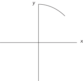
This problem is an example of a scan conversion: converting a geometric drawing to a pixel-based raster image. You need an equation for a circle before you can calculate anything. The common mathematical function that produces a circle is:

This definition is nice because it contains x’s, y’s, and r’s, just like your problem and your coordinate system. You must figure out how to determine pairs of coordinates (x, y) on the circle using the equation, x2 + y2 = r2. The easiest way to find a pair of coordinates is to set a value for one and then calculate the other. It’s more difficult to set y and calculate x because after the scan conversion there will be several x values for certain y values. Therefore, you should set x and calculate y. Doing some algebra, you can calculate y with the following equation:
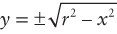
In this problem you deal with only positive values of y, so you can ignore the negative root. This produces the following:
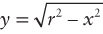
For example, given an x coordinate of 3 and a radius of 5, ![]() . You now know how to calculate y, given x. Next, you need to determine the range of x values. x clearly starts at 0, but where does it end? Look again at the figure to try to figure out visually how you know that you are at the end of the one-eighth of the circle. In visual terms, this happens when you are farther out than you are up. In mathematical terms, this means that the x value becomes greater than the y value. Thus, you can use the x range from 0 until x > y. If you put these pieces together, you have an algorithm for drawing a circle. In outline form:
. You now know how to calculate y, given x. Next, you need to determine the range of x values. x clearly starts at 0, but where does it end? Look again at the figure to try to figure out visually how you know that you are at the end of the one-eighth of the circle. In visual terms, this happens when you are farther out than you are up. In mathematical terms, this means that the x value becomes greater than the y value. Thus, you can use the x range from 0 until x > y. If you put these pieces together, you have an algorithm for drawing a circle. In outline form:
Start with x = 0 and y = r.While (y ≤ x)Determine theycoordinate using the equation:Set the pixel (x, y)Increment x
This algorithm looks correct, but there is a subtle bug in it. The problem arises from treating the y coordinate as an integer, when often y will be a decimal value. For example, if y had the value 9.99, setPixel would truncate it to 9, rather than round to the y pixel of 10 as you probably want. One way to solve this problem is to round all values to the nearest whole integer by adding 0.5 to y before calling setPixel.
This change results in a much better-looking circle. The code for this algorithm is as follows:
void drawEighthOfCircle( int radius ){int x, y;x = 0;y = radius;while ( y <= x ){y = Math.sqrt( ( radius * radius ) – ( x * x ) ) + 0.5;setPixel( x, y );x++;}}
What’s the efficiency of this algorithm? Its running time is O(n), where n is the number of pixels that you need to set. This is the best possible running time because any algorithm would have to call setPixel at least n times to draw the circle correctly. The function also uses the sqrt function and multiplies during each iteration of the while loop. The sqrt function and the multiplications are likely to be slow operations. Therefore, this function probably isn’t practical for most graphical applications where speed is critical. Faster circle-drawing algorithms exist that don’t make repeated calls to slow functions like sqrt or have repeated multiplications, but you wouldn’t be expected to implement them during an interview.
Rectangle Overlap
Before you jump into the problem, it’s helpful to work out a few properties about rectangles and their vertices. First, given the upper-left (UL) and lower-right (LR) corners, it is not difficult to get the upper-right (UR) and lower-left (LL) corners. The coordinates of the upper-right corner are the upper left’s y and the lower right’s x. The lower-left corner is at the upper left’s x and the lower right’s y.
It is also useful to determine whether a point falls inside a rectangle. A point is inside a rectangle if the point’s x is greater than the rectangle’s UL corner’s x and less than the rectangle’s LR corner’s x, and the point’s y is greater than the rectangle’s LR corners’s y and less than the rectangle’s UL corner’s y. You can see this in Figure 14-2, where point 1 is inside rectangle A. Now you can move on to the problem.
This problem seems straightforward. Start by considering the ways in which two rectangles can overlap. Try to divide the different ways into various cases. A good place to begin is by examining where the corners of a rectangle end up when it overlaps another. Perhaps you can enumerate the ways in which two rectangles can overlap by counting the number of corners of one rectangle that are inside the other rectangle. The cases that you must consider are when one of the rectangles has 0, 1, 2, 3, or 4 corners inside the other. Take these cases one at a time. Begin by considering a case in which no corners of either rectangle are inside the other. This is illustrated in Figure 14-3.
Consider what conditions must be true for two rectangles to overlap without having any corners inside each other. First, the wider rectangle must be shorter than the narrower rectangle. Next, the two rectangles must be positioned so that the overlap occurs. This means that the narrower rectangle’s x coordinates must be between the wider rectangle’s x coordinates, and the shorter rectangle’s y coordinates must be between the taller rectangle’s y coordinates. If all these conditions are true, you have two rectangles that overlap without having any corners inside of each other.
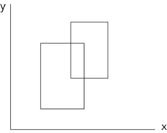
Now consider the second case, in which rectangles may overlap with one corner inside the other. This is illustrated in Figure 14-4. This case is relatively easy. You can simply check whether any of the four corners of one rectangle are inside the other rectangle.
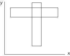
In the third case, the rectangles may overlap if two points of one rectangle are inside the other. This occurs when one rectangle is half in and half out of the other rectangle, as illustrated in Figure 14-5. Here, one rectangle has no corners inside the other, and one rectangle has two corners inside the other. If you check the corners of the rectangle with no corners inside the other, you will not find overlap. If you check the rectangle with two corners overlapping, you must check at least three corners to determine overlap. However, you can’t determine ahead of time which rectangle will have no corners inside the other. Therefore, you must check at least three corners of each rectangle to properly test for overlap.
The three-point case is simple: it’s just not possible. No matter how you draw the rectangles, you can’t arrange them so that one rectangle has exactly three corners inside the other.
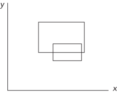
The four-corner case is possible. This happens if one rectangle completely contains the other, as shown in Figure 14-6. If you check one corner of both rectangles, you can correctly determine overlap in this case.

Now, put your tests to determine overlap in the zero-corner, one-corner, two-corner, and four-corner cases together to encompass all these cases. These tests check the widths, heights, and positions of both rectangles, the four corners of one rectangle, the three corners of each rectangle, and the one corner of each rectangle, respectively. You could test each of these cases individually, but that’s repetitive. Instead, try to develop a single test that encompasses all these cases. Start by checking the widths, heights, and positions of both rectangles to cover the zero-corner case. Next, check the four corners of one rectangle to cover the one-corner case. Then, to include the two-corner case, check three corners of the other rectangle. Luckily, the four-corner case is already covered if you check four corners of one rectangle and three of the other because you’re clearly checking one corner of each. The composite test to determine rectangle overlap is to check the following:
- The heights, widths, and positions of both rectangles
- Whether any of the four corners of one rectangle are inside the other
- Whether any of three corners from the second rectangle are inside the first
This solution to test for overlap is correct, but it seems inefficient. It checks the heights, widths, and positions of both rectangles as well as seven of eight possible corners—and each corner check requires four comparisons. This results in 34 comparisons to calculate the answer.
Perhaps there is a better solution. Another way to think about the problem is to consider when the rectangles don’t overlap, as opposed to when they do overlap. If you know when the rectangles don’t overlap, you know when they do overlap. The conditions for not overlapping are much more straightforward. Call the two rectangles A and B. A and B do not overlap when A is above B, or A is below B, or A is to the left of B, or A is to the right of B. More than one of these conditions can be true at the same time. For example, A could be above and to the right of B. If any one of these conditions is true, the two rectangles do not overlap. The specifics of these conditions can be summarized as follows.
The two rectangles do not overlap when:
- A’s UL’s x value is greater than B’s LR’s x value or
- A’s UL’s y value is less than B’s LR’s y value or
- A’s LR’s x value is less than B’s UL’s x value or
- A’s LR’s y value is greater than B’s UL’s y value.
This solution is much simpler, requiring only four comparisons and one negation. You can implement the function as follows:
boolean overlap( Rect a, Rect b ){return !( a.ul.x > b.lr.x ||a.ul.y < b.lr.y ||a.lr.x < b.ul.x ||a.lr.y > b.ul.y );}
This function works, but you can do even better. You can get rid of the logical NOT. A bit of logic theory called DeMorgan’s Law may be helpful here. This law states the following:
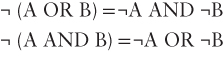
In addition, you should recognize that:
- ¬(A > B) is equivalent to (A ≤ B)
Working through these rules, you get the following function:
boolean overlap( Rect a, Rect b ){return( a.ul.x <= b.lr.x &&a.ul.y >= b.lr.y &&a.lr.x >= b.ul.x &&a.lr.y <= b.ul.y );}
To ensure that you didn’t make a mistake, it’s a good idea to verify that these conditions make sense. The preceding function determines that two rectangles overlap if:
- A’s left edge is to the left of B’s right edge and
- A’s upper edge is above B’s bottom edge and
- A’s right edge is to the right of B’s left edge and
- A’s bottom edge is below B’s upper edge.
These conditions mean that rectangle B cannot be outside of rectangle A, so there must be some overlap. This makes sense.
BIT MANIPULATION PROBLEMS
Bit manipulation problems may span the range from dead simple to extremely difficult. In some cases, a single problem covers this whole range with different solutions of increasing efficiency and complexity.
Big-Endian or Little-Endian
This problem tests your knowledge of computer architectures as much as it tests your ability to program. The interviewer wants to know whether you are familiar with the term endian. If you are familiar with it, you should define it or at least try to point out the differences between big-endian and little-endian, even if you forget which is which. If you are not familiar with the term, you’ll have to ask the interviewer to explain it.
Endianness refers to the order in which a computer stores the bytes of a multibyte value. (Or technically, the units of a multiunit value—for example, the computer may use a 16-bit unit size instead of an 8-bit unit size. We restrict this discussion to 8-bit units for simplicity.) Computers use multibyte sequences to represent certain primitive data types.
The bytes within an integer can be arranged in any order, but they are almost always either least-significant byte (LSB) to most-significant byte (MSB) or MSB to LSB. Significance refers to the place value a byte represents within a multibyte value. If a byte represents the lowest place values, the byte is the LSB. For example, in the hexadecimal number 5A6C, 6C is the LSB. Conversely, if a byte represents the highest place values, it is the MSB. In the 5A6C example, 5A is the MSB.
In a big-endian machine the MSB has the lowest address; in a little-endian machine the LSB has the lowest address. For example, a big-endian machine stores the 2-byte hexadecimal value A45C by placing A4 in the lower-address byte and 5C in the next. In contrast, a little-endian machine stores 5C in the lower-address byte and A4 in the next.
Endianness is usually transparent to the programmer as long as data remains on systems of the same type. When data is exchanged between different systems that have different endianness, problems may arise. Most programming languages default to writing data to files and network devices using the system’s native byte ordering (endianness)—that is, using the same ordering that the bytes have in memory. This means that data written by an endianness-naïve program running on a little-endian system is likely to be misinterpreted by the same program running on a big-endian system. For the most part endianness is determined by the processor, but the Java virtual machine is big-endian regardless of the underlying processor type.
To answer the problem, you must choose a multibyte data type to work with. It’s not important which one you choose, just that the type is more than 1 byte. A 32-bit integer is a good choice. You need to determine how you can test this integer to figure out which byte is the LSB and which is the MSB. If you set the value of the integer to 1, you can distinguish between the MSB and the LSB because in an integer with the value 1, the LSB has the value 1 and the MSB has the value 0.
Unfortunately, it’s not immediately clear how to access the bytes of an integer. You might try using the bit operators because they allow access to individual bits in a variable. However, they are not particularly useful because the bit operators act as if the bits are arranged in order from most-significant bit to least-significant bit. For example, if you use the shift-left operator to shift the integer 8 bits, the operator works on the integer as if it were 32 consecutive bits regardless of the true byte order in memory. This property prevents you from using the bit operators to determine byte order.
How can you examine the individual bytes of an integer? A C character is a single-byte data type. It could be useful to view an integer as four consecutive characters. To do this, you create a pointer to the integer. Then, you can cast the integer pointer to a character pointer. This enables you to access the integer like an array of 1-byte data types. Using the character pointer, you can examine the bytes and determine the format.
Specifically, to determine the computer’s endianness, get a pointer to an integer with the value of 1. Then, cast the pointer to a char *. This changes the size of the data to which the pointer points. When you dereference this pointer, you access a 1-byte character instead of a 4-byte integer. Then you can test the first byte to see if it is 1. If the byte’s value is 1, the machine is little-endian because the LSB is at the lowest memory address. If the byte’s value is 0, the machine is big-endian because the MSB is at the lowest memory address. In outline form, here is the procedure:
Set an integer to 1Cast a pointer to the integer as a char *If the dereferenced pointer is 1, the machine is little-endianIf the dereferenced pointer is 0, the machine is big-endian
The code for this test is as follows:
/* Returns true if the machine is little-endian, false if the* machine is big-endian*/bool isLittleEndian(){int testNum;char *ptr;testNum = 1;ptr = (char *) &testNum;return (*ptr); /* Returns the byte at the lowest address */}
This solution is sufficient for an interview. However, because the goal of an interview is not just to solve problems but also to impress your interviewer, you may want to consider a slightly more elegant way to solve this problem. It involves using a feature of C called union types. A union is like a struct, except that all the members are allocated starting at the same location in memory. This enables you to access the same data with different variable types. The syntax is almost identical to a struct. Using a union, the code is as follows:
/* Returns true if the machine is little-endian, false if the* machine is big-endian*/bool isLittleEndian(){union {int theInteger;char singleByte;} endianTest;endianTest.theInteger = 1;return endianTest.singleByte;}
Number of Ones
This problem may at first sound like a base conversion problem in which you need to design an algorithm to convert a base 10 number to a two’s complement binary number. That approach is circuitous because the computer already stores its numbers in two’s complement binary internally. Instead of doing a base conversion, try counting the 1s directly.
You can count the number of 1s by checking the value of each bit. Ideally, you’d like to use an operator that would tell you the value of a specified bit. That way, you could iterate over all the bits and count how many of them were 1s. Unfortunately, this ideal operator doesn’t exist.
You can begin by trying to create a procedure that determines the value of each bit using the existing bit operators. Focus on figuring out a way to get the value of the lowest bit. One way to do this is to AND the given integer with the value 1. You can use 8-bit integers to keep the examples manageable, so 1 is stored as 00000001. The result of the AND with 1 would be either 00000000 if the given integer’s lowest bit had the value 0, or 00000001 if the given integer’s lowest bit had the value 1. In general, you can get the value of any bit if you create the correct mask. In this case, the mask is an integer with all the bits set to 0 except the bit you’re checking, which is set to 1. When you AND a mask with the value you’re checking, the result is either a 0, indicating that the bit you are checking has the value 0, or a nonzero result, indicating that the bit you are checking has the value 1.
You could create a mask for each of the bits and count the number of 1 bits. For example, the first mask would be 00000001, followed by masks of 00000010, 00000100, 00001000, and so on. This would work, but your interviewer probably doesn’t want to watch you write out that many masks. Consider the differences between each mask. Each mask is the same as the previous mask, but the 1 bit is moved one place to the left. Instead of predefining your masks, you can construct them using the left-shift operator. Simply start with a mask of 00000001 and repeatedly shift the integer 1 bit to the left to generate all the necessary masks. This is a good technique, and if you work it out to its conclusion, it yields an acceptable answer. However, there’s a prettier and slightly faster solution that uses only one mask.
Think about what you can do with a single mask. You are trying to examine each bit of the integer, so you need to mask a different bit on each iteration. So far, you’ve been accomplishing this by shifting the mask and keeping the integer in place, but if you shifted the integer, you could examine all its bits using the same mask. The most natural mask to use is 00000001, which yields the least-significant bit. If you keep shifting the integer right, each bit will eventually become the rightmost bit. Try working through 00000101 as an example. The rightmost bit is 1, so you would add 1 to your count and shift the integer right, yielding 00000010. This time the rightmost bit is 0. Shifting right again produces 00000001. The least significant bit in this integer is 1, so you would increment your count to 2. When you shift right a third time, the integer becomes 00000000. When the integer’s value reaches zero, there are no 1 bits remaining, so you can stop counting. As in this example, you may not have to iterate through all the bits to count all the 1s, so in many cases this algorithm is more efficient than the multiple mask algorithm. In outline, the single mask algorithm is as follows:
Start with count = 0While the integer is not 0If the integer AND 1 equals 1, increment countShift the integer one bit to the rightReturn count
Finally, check for any error cases in this code; look for problems with positive numbers, negative numbers, and zero. If the integer has the value of 0, the algorithm immediately and correctly returns that there are zero 1s in the binary representation. Now consider the case in which you are passed a negative number. You will shift the number to the right, but the new bit added on the left becomes a 1 and not a 0 if the right-shift operator does sign extension. The solution to this depends on the language you’re using. If the language supports unsigned types (for example C, C++, and C#) you can read the value as an unsigned integer. In languages without unsigned types, there’s usually a special operator that right-shifts without sign extension (>>> in Java and JavaScript). Using either >>> or an unsigned integer means that the shift operator will not sign extend, and the new bits added during the right shifting will be 0s. The number eventually becomes all 0s. Finally, consider the case in which you are given a positive integer. This is the sample case that you worked with, and the algorithm works correctly here.
The code for this algorithm in Java is as follows:
int numOnesInBinary( int number ) {int numOnes = 0;while ( number != 0 ){if ( ( number & 1 ) == 1 ) {numOnes++;}number = number >>> 1;}return numOnes;}
What’s the running time of this function? The function iterates through the while loop until all the 1s have been counted. In the best case, the given integer is 0, and the function never executes the while loop. In the worst case, this is O(n), where n is the number of bits in an integer.
Unless you’re incredibly good at bitwise operations, this is the best solution you’re likely to come up with in an interview. Better solutions exist, though. Consider what happens at the bit level when you subtract 1 from a number. Subtracting 1 produces a value that has all the same bits as the original integer except that all the low bits up to and including the lowest 1 are flipped. For example, subtracting 1 from the value 01110000 results in the value 01101111.
If you apply the AND operation to the integer and the result of the subtraction, the result is a new number that is the same as the original integer except that the rightmost 1 is now a 0. For example, 01110000 AND (01110000 – 1) = 01110000 AND 01101111 = 01100000.
You can count the number of times that you can perform this process before the integer’s value reaches 0. This is the number of 1s in the computer’s representation of the number. In outline form this algorithm is as follows:
Start with count = 0While the integer is not zeroAND the integer with the integer – 1Increment countReturn count
Here is the code:
int numOnesInBinary( int number ){int numOnes = 0;while ( number != 0 ){number = number & ( number – 1 );numOnes++;}return numOnes;}
This solution has a running time of O(m), where m is the number of 1s in the solution. Even this is not the best solution. One of the best solutions implements a parallel approach that uses bit operations to simultaneously count the number of bits in each adjacent pair of bits and then (in parallel) sums adjacent units of 4 bits, 8 bits, and so on, arriving at a solution in O(log n) time (where n is the number of bits in the integer). A version of this algorithm appeared in an early programming textbook, The Preparation of Programs for an Electronic Digital Computer, Maurice V. Wilkes, David J. Wheeler, Stanley Gill. Addison Wesley (1951).
The operation described by this problem is commonly referred to as a population count. Population counts have several applications, notably in cryptography. In fact, they’re useful enough that many processors implement population count in hardware with a single instruction. Some compilers allow access to this instruction through extensions, for example __builtin_popcount() in the Gnu Compiler Collection and __popcnt() in Microsoft Visual C++. When the processor supports it, these are by far the fastest way to perform a population count.
Keep in mind that these additional solutions were presented for interest, and the first solution is likely all that would be expected in an interview.
SUMMARY
Problems involving bit manipulation and computer graphics are common in interviews. Unless you’re applying for a graphics-oriented position, the graphics problems you encounter will usually be fairly basic. Carefully enumerate and check all possible special cases and watch for rounding issues when converting between floating-point math and fixed-pixel positions. Bit manipulation problems are more common than graphics problems. Depending on the type of programming you do, you may not use bit operations often, so refamiliarize yourself with the bit operators and their use before your interview.