Learning Topics
My Blocks , geometry , unit conversion , calibration , feedback , looping constructs , proportional control, variables, conditional constructs , torque , and traction
Requirements
- 1.
Move forward or backward a specified distance.
- 2.
Ensure movement is straight (i.e., eliminating the “wiggle”).
Simple My Block to Move Forward a Specified Distance
Learning topics covered: My Blocks, geometry , unit conversion , calibration
In virtually every mission a robot attempts, it must move forward or backward, and often both. The Move Steering and Move Tank blocks allow for movement in units of seconds, wheel rotations, or degrees of wheel rotation. Although there could be special circumstances when it would be desired to move your robot for a certain time, normally it is desired to move the robot a certain distance. Thus, the seconds option is typically not useful. Inputting wheel rotations or degrees of wheel rotation is useful, but it is handy to translate these units to a linear distance on the mat. In other words, it is much easier to think about telling the robot to go forward 10.5" instead of 1.5 wheel rotations or 540° of wheel rotation.
We can create a My Block to go forward a specified distance in inches by using a Math block and a Move Steering block . We use the Math block, along with a measurement and some simple geometry , to translate inches to degrees of wheel rotation. This process is called unit conversion , and it is very common in engineering.


Circle diameter and circumference


Start of Forward My Block
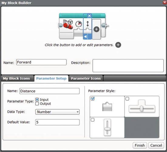
Builder window for first Forward My Block

First Forward My Block, complete
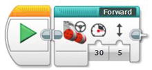
Forward My Block in Program
There are at least two options for making the robot move backward instead of forward. The first option is to enter a negative number into the My Block for either the Power or the Distance. The advantage of this approach is that a new My Block is not needed; it can be done immediately. A disadvantage is that it can be confusing to understand a program that uses “Forward” My Blocks to move both forward and backward. A second disadvantage is that simply entering a negative value will not work for the advanced version of the Forward My Block that uses acceleration and deceleration to prevent wheel slip (this is covered in Chapter 7).
I recommend creating a second My Block named “Backup ,” which is very easy to do. Go to the Project Properties tab (far left, wrench icon), then the My Blocks tab within the window, and select Forward.ev3p. Click the Copy button, followed by the Paste button. A new My Block named Forward2.ev3p should now be present. Double-click it to open the new My Block.

First Backup My Block, complete
If you want to teach your students about calibration , have them take careful measurements of the robot’s forward and backward travel, compare those measurements to the value entered into the My Block, and increase or decrease the conversion factor until the robot travels exactly the distance specified. Note that longer distances are better than shorter distances for this type of calibration, and that low power levels should be used so that wheel slip does not introduce random error into the distance traveled.
Although calibration is a useful concept to teach students, for the purposes of competition it is not practical because most distances traveled on the mat will be determined by trial and error anyway. It is nevertheless helpful to have My Blocks with distance values in inches because it is an intuitive measurement unit.
Eliminating the “Wiggle ” Using a Gyro Sensor
Learning topics covered: My Blocks , feedback , looping constructs , proportional control, variables

Small “wiggle ” can create substantial navigation error
The basic Forward My Block can be modified to correct the wiggle , but three new concepts are used to do so: feedback , program loops , and proportional control. Feedback will be used from a gyro sensor to determine whether the robot is traveling straight ahead. If the robot veers to the left or right, an error signal will be used to generate steering correction. A program loop will be needed because the process of checking sensor values and correcting the steering must be done rapidly and repeatedly. Implementing this technique creates what is called a proportional controller. A brief overview of this type of controller is in order before making an improved version of the Forward My Block.
Imagine you are driving a car. You look through the windshield to see the road in front of the car. If the car veers toward the left a little bit, you respond by turning the steering wheel slightly to the right so that the car returns to the center of the lane. If the car veers sharply to either side, you respond by turning the steering wheel a large amount in the opposite direction so that the car returns quickly to the center of the lane. The distance of the car from the center of the lane is called the error . The center of the lane, or desired value, is called the set point. The goal is to stay at the set point (center of the lane) and keep the error at zero. When the error is not zero, the amount of steering adjustment needed is called the correction. The term for this approach is proportional control because the amount of correction is proportional to the amount of error. Next, we modify the Forward My Block to use proportional control to correct any error caused by the “wiggle .”

Gyro sensor orientation
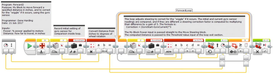
Forward2 My Block to move forward with wiggle correction
This program needs to read the direction of the robot before any movement. This will be the reference value used to make sure the robot is pointing in the correct direction, and the basis for computing any errors and steering corrections. The element used to store this value is called a variable. The Variable block is the first item in the Data Operations tab . Place one on the program chain right after the motor B Rotation Sensor reset block. Click in the white box at the block’s upper right, select “Add Variable,” name it GyroStart , and configure it to “Write – Numeric.” Insert a Gyro Sensor block from the Sensor tab, right after the motor B Rotation Sensor reset block, set the port to match the port to which it is connected on the brick, and configure it to “Measure – Angle.” Connect its output to GyroStart, so its value will be copied, or “written,” to the variable at the beginning of the My Block’s operation. Note that, because the gyro sensor’s initial value is stored in GyroStart, the gyro sensor does not need to be reset. This preserves its value just in case it is being used before and after this My Block for something else.
Add a loop to the program flow and reposition the Move Steering block inside the loop.
Change the mode of the Move Steering block to On.
Set the mode of the loop exit criterion to Motor Rotation – Degrees, set the condition to 3 (≥), and set the port to B.
Connect the output of the Math block Distance calculation to the Threshold Value input of the loop exit criterion.
Add a Gyro Sensor block to the beginning of the loop, just before the Move Steering block , set its mode to “Measure – Angle,” and set its Port input to the correct port. Next, add a Variable block after the Gyro Sensor block, set its mode to “Read – Numeric,” and set its Variable Name to GyroStart . Then add a Math block after the Gyro Sensor block and set its mode to ADV. (Using the Advanced mode will allow for creating a formula with more than two variables.) Connect its output to the Steering input of the Move Steering block .

Although the error value could be passed directly to the Steering input of the Move Steering block , in control systems this value is normally multiplied by another number called the gain . If the raw error value is too small, the correction is too slow. In this case a gain > 1 is used. If the raw error value is too large, the system is unstable. Consider the earlier car steering example, and imagine moving the steering wheel a large amount in response to even the smallest error. The result would be that the car would weave back and forth, or even veer off the road: an unstable system. In this case a gain < 1 would be used to stabilize the system.


Connect the GyroStart variable output within the loop to the “a” input of the Math block.
Connect the Gyro Sensor block output within the loop to the “b” input of the Math block.
Set the “c” input to 1.
Click in the formula box at the upper right and type the formula (a-b)*c.
At this point the data wire connecting to the Threshold Value of the Loop block is probably misaligned because of the extra blocks added to the loop. To fix this, unplug the data wire from the loop, let it go, and redo the connection. Next, connect the My Block Power input to the Power input of the Move Steering block (same as with the Forward My Block).
The last thing to do before tuning is to make sure the robot stops as soon as it reaches the specified distance. Add a Move Steering block to the end of the program chain, after the Loop block. Set its mode to Off and Brake at End parameter to True (check mark). The My Block is now ready to be tuned (i.e., figure out what value to use for the Gain parameter).
It is often effective to begin tuning by setting the Gain parameter to 1, then running the program. If it oscillates back and forth instead of moving forward, the system is unstable and the gain needs to be reduced. Reduce the gain by an order of magnitude (i.e., from 1 to 0.1, then to 0.01, etc.) until it does not oscillate. If the system does not oscillate, increase the Gain by an order of magnitude (1 to 10, then to 100, etc.) and try it again. Continue increasing the Gain until it oscillates, then reduce the Gain until it is stable. Oscillation is bad, but a Gain value near the point where it starts to oscillate is good because the steering is corrected faster. The appropriate Gain value will depend on characteristics of the robot, including wheel base and tire diameter. For the robot used to test these programs, a final value of Gain = 5 worked well. The final program is shown in Figure 3-9.
The Distance conversion factor must be negated because the motor counters will be starting at zero and decrementing to negative values.
For the same reason, the Compare Type to exit the Loop block must be changed from “≥” to “≤.”
The correction formula must be reversed. This can be done by changing the formula from “(a-b)*c” to “(b-a)*c,” or by negating the gain value, “c.” (Make one of the two changes, but not both. Doing both will result in the same formula because the two “negatives” will cancel each other.)
A Math block must be added before the loop to negate the Power input before it is passed to the Move Steering block inside the loop.
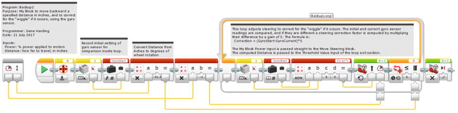
Backup2 My Block
Conclusion
This chapter covered how to make your robot move forward and backward in a straight line for a specific distance. Although forward and backward movements are important for navigating, they are not sufficient. The next chapter addresses turning.