Learning Topics
My Blocks , geometry , unit conversion , calibration , torque , traction , dead reckoning , and parallel execution
Requirement
Turn left or right to an angle specified in degrees
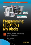
Turning options
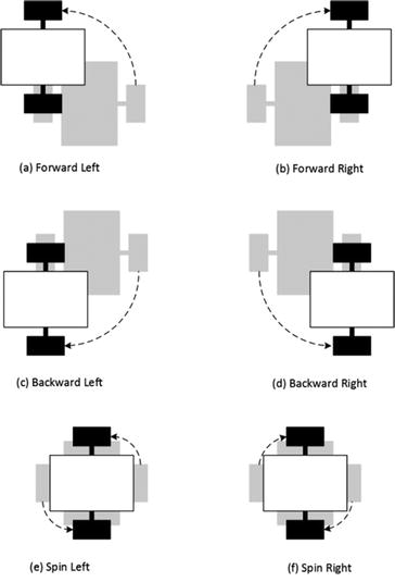
Tire profile comparison
Turning Left and Right
Learning topics covered: My Blocks , geometry , unit conversion , torque , traction
Although it is possible to construct one My Block that can perform all four turn types (a–d), it is arguably better to use one My Block for right turns and another for left turns. There are at least two reasons to do so. First, the code becomes somewhat self-commenting as a block named TurnRight clearly implies the robot is going to turn right, even with no comment added. Second, a fringe benefit is that the My Block code is simpler.
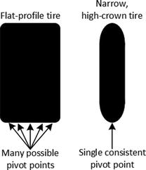
To create an intuitive turn My Block, desired degrees of turn angle for the robot must be converted to degrees of wheel rotation for the appropriate drive motor. In the forward and backup My Blocks , we converted inches of linear movement to degrees of wheel rotation. A similar exercise in geometry and algebra will allow a straightforward conversion from turning angle degrees.

Degrees of turning angle vs. axle rotation

TurnRight My Block code

TurnRight My Block in a program, to turn 20° at 20 percent power

TurnLeft My Block
Spinning Left and Right
Learning topics covered: My Blocks , geometry , unit conversion , torque , traction
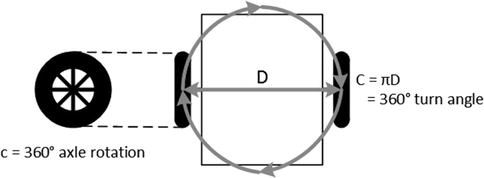
Degrees of spin angle vs. axle rotation
This means that the conversion factor for the spin My Blocks will be about half of the conversion factor in the turn My Blocks . Because both motors are driven, the first block will be the Math block to convert turning angle into degrees of wheel rotation, with the smaller multiplier. Add a second Math block to invert (multiply by -1) the output for the right motor, which will turn backward. As in the TurnRight My Block, next comes the Large Motor block to rotate the B motor forward. Its Power input comes from the My Block’s Power input, and its Degrees input comes from the first Math block’s output.
Now we will do something that is a new feature with the EV3 software: operate two sections of code in parallel simultaneously, i.e., parallel execution. Add a second Large Motor block to run the C motor in mode “On for Degrees,” but place it below instead of to the right of the other Large Motor block.
Next, use the pointer to “grab” the Sequence Plug Exit of the second Math block (not the data wire output port; the output plug at the right end of the Math block) and connect it to the Sequence Plug Entry of the C motor block. When you do that, the program will automatically shift the other motor block to the right, making it obvious that parallel operation is occurring. Connect the numeric data output of the second Math block to the Degrees input, and the Power input of the My Block to the motor block’s input, as shown in Figure 4-8.

SpinRight My Block
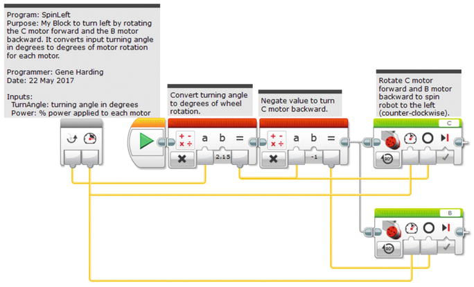
SpinLeft My Block
Conclusion
If you have created all of the My Blocks up to this point in the book, you have what you need to navigate anywhere on a challenge board using what is called dead reckoning . In dead reckoning navigation , one’s position is calculated from a starting point based on the distance and direction traveled. The problem with dead reckoning is that any errors in those calculations tend to be larger as distance traveled gets larger. For instance, if you point your robot at an object on the board and program it to go forward, it might come within a fraction of an inch of its intended mark if that mark is a short distance away. On the other hand, if it must travel several feet to get there, it could be off by more than an inch, which could result in a failed mission.
“Go up the street that direction and take a left at the stop sign. Turn right at the first traffic light, then go about ¾ mile and turn left just before the gas station. The store will be on the right.”
Those landmarks—stop sign, traffic light, gas station—are waypoints, fixed points of reference that can be used to adjust, or correct, dead reckoning navigation . FLL challenge boards always have lines on the mats and border walls that can be used for such corrections to improve navigation precision. The next two chapters deal with using lines and border walls for this purpose.