Learning Topics
My Blocks, geometry, unit conversion, calibration, feedback, looping constructs, proportional control, variables, conditional constructs , torque, and traction
Requirements
- 1.
Move forward or backward a specified distance.
- 2.
Ensure movement is straight (i.e., eliminate the “wiggle”).
- 3.
Enable optional “handoffs” so the robot does not have to stop at the end of the My Block.
- 4.
Move as quickly as possible without wheel slip.
Handoffs: Continuing at Speed When the My Block Ends
Learning topics covered: My Blocks, conditional constructs
There are arguably two primary challenges to navigating a challenge board: precision and speed. The handoff technique deals with the constraint of time, and thus addresses the issue of navigation speed. Time is an important factor because each FLL Robot Game round only lasts 2.5 minutes, or 150 seconds. Saving a few seconds here and there can allow for more completed missions to achieve higher point totals.
To illustrate the usefulness of a handoff, consider the start of a mission set programmed by one of my former teams. The robot had to go forward more than 20", detect a line, curve to the left, detect another line, follow that line to its intersection with another line, then continue following the second line for a specified distance before making a right turn. It was necessary to stop before making the right turn, but not any time before. Imagine how the run would look if the robot stopped after every single My Block leading up to the turn: forward, stop, find line, stop, curve left, stop, find line, stop, follow line, stop, find line, stop, follow line, stop, turn right. All of these unnecessary stops waste time. If each stop wastes around 0.5 seconds, then just the beginning portion of the mission set would waste 3.0 seconds. Using the handoff technique saved several seconds per mission set, which allowed the team to add a few missions to their Robot Game strategy. The savings are even greater when acceleration and deceleration are used in the Forward and Backup My Blocks (covered later).
Switch block
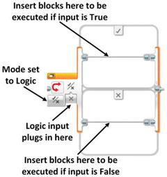
The second addition will be an input to tell the robot which branch of the Switch block to follow. Because there are only two possibilities, a Logic input will work well (i.e., either True or False). Let’s name the input BrakeAtEnd. If BrakeAtEnd is True, the robot will stop when it reaches the end of the My Block; if it is False, the robot will continue moving at its present speed and control will pass to the next program block.
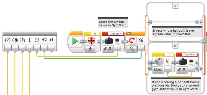
The wiggle correction code creates an issue with Handoffs that will require more changes. Imagine a handoff between two My Blocks, both of which perform wiggle correction to keep the robot going straight. Now, suppose the first My Block is in the middle of doing a correction when it reaches the specified distance, so it is not pointed quite straight ahead. What happens when the next My Block begins? It loads GyroStart with the current direction and starts tracking that direction, which is slightly off. We can fix this problem by passing the GyroStart value from one My Block to the next.
Add logic input BrakeAtEnd to indicate whether robot should stop, or not, after executing this My Block.
Add Switch block at end to either stop robot or continue at speed, depending on value of BrakeAtEnd.
Add numeric output GyroOut to pass GyroStart value to next My Block.
Add numeric input GyroIn to receive GyroStart value from previous My Block.
Add logic input RcvHandoff to indicate whether the My Block is receiving a Handoff or not.
Add a Switch block at the beginning to load GyroStart with either GyroIn or the current direction, depending on the value of Handoff.
Add a GyroStart variable to the end of the program chain, in “Read – Numeric” mode, and wire its output to the GyroOut output of the My Block.
Because Forward3 will have new inputs and a new output, it cannot simply be copied from Forward2 in the Project Properties window. A new My Block must be created using the My Block Builder. The good news, however, is that the blocks can be copied from inside Forward2 so that the entire program does not have to be re-created from scratch. Begin by copying Forward2 in the Project Properties window, then go to the programming window for the new My Block, double-click the tab, and rename the new My Block “Temp.” It will be deleted later.
In Temp, unplug the Distance input from the first Math block, and the Power input from the loop. Now the program blocks can be copied to a new program without leaving “hanging” connections from the My Block inputs. (It is safer to make a temporary program for this purpose than to modify the original My Block and redo the connections later.)
BrakeAtEnd: Parameter Type Input, Data Type Logic, Default Value True, and select an appropriate icon.
Distance: Parameter Type Input, Data Type Number, Default Value 5, and select an appropriate icon.
Power: Parameter Type Input, Data Type Number, Default Value 30, and select an appropriate icon.
GyroIn: Parameter Type Input, Data Type Number, Default Value 0, and select an appropriate icon.
GyroOut: Parameter Type Output, Data Type Number, and select an appropriate icon.
RcvHandoff : Parameter Type Input, Data Type Logic, Default Value False, and select an appropriate icon.
Double-check to make sure everything is correct, then click Finish to create the My Block.
Now you are ready to set up Forward3 to allow Handoffs, but first drag the output block for GyroOut out of the way so it does not get covered up as you add programming blocks. Begin by adding a Switch block to the very end of the program, and set the mode to Logic. If BrakeAtEnd is true, the robot should stop, so drag the last Move Steering block (the one with mode set to Off) into the True branch of the Switch block, then use a data wire to connect the BrakeAtEnd My Block input to the Logic input of the Switch block. As before in Forward2, connect the Distance input to the “a” input of the first Math block and the Power input to the first Move Steering block (the one inside the loop).
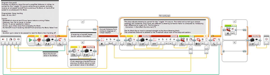
Forward3 My Block with option to stop or continue running at end
Negate the Distance conversion factor because the motor counters will be starting at zero and decrementing to negative values.
Change the Loop block exit condition from “≥” to “≤”.
Reverse the steering correction by changing the formula from “(a-b)*c” to “(b-a)*c”, or by negating the gain value, “c”.
Add a Math block before the loop to negate the Power input before it is passed to the Move Steering block inside the loop.
Of course, remember to adjust the comments appropriately.
Accelerating and Decelerating Using Forward3 My Blocks
Learning topics covered: My Blocks, torque , traction
This section and the next address the fourth requirement stated at the beginning of this chapter: Move as quickly as possible without wheel slip. The problem is traction. If the motor power is set to a starting value that is too high, the wheels or tires can slip (i.e., “peel out”) as the robot picks up speed from a standstill. Likewise, the wheels can skid if the robot stops suddenly. The solution presented here is to accelerate smoothly to some maximum speed, then decelerate smoothly.
A relatively simple solution uses the Forward3 My Block from the previous section. Acceleration and deceleration will be implemented in discrete steps by cascading multiple Forward3 blocks together. The following example describes how to begin from a standstill, accelerate to a top speed, and then decelerate and stop. It uses several Forward3 blocks, and requires some trial and error to verify proper operation.
A starting power of 20 percent will not generate wheel slip.
Power increases in steps of 20 percent will not generate wheel slip while the robot is moving.
1" is a sufficient distance for each acceleration step.
Maximum desired power is 80 percent.
Distance to move is 20".
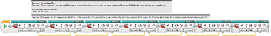
Acceleration and deceleration implemented with cascaded Forward3 My Blocks
If wheel slip occurs, which might only be noticeable by observing inconsistent distances, the acceleration and deceleration could be made less aggressive by using smaller power increments and decrements at each step. Alternatively, if quicker transit time is desired, the program could be made more aggressive by using larger power steps if it does not cause wheel slippage.
This approach to acceleration, although it works, is tedious to use inside a program and can result in very large programs.
Accelerating and Decelerating with a Single My Block
Learning topics covered: My Blocks, geometry , unit conversion , feedback , looping constructs , proportional control , variables, conditional constructs , torque , traction
Implementing acceleration and deceleration inside a single My Block results in cleaner programs, but the My Block itself involves a substantial increase in complexity over any of the programs developed to this point in the book. If done well, however, it should be simpler to use, smoother, and less error prone.


Basic accelerate /decelerate plots
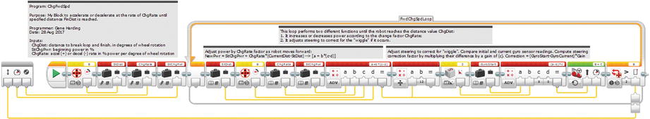
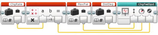
We define ChgRate as a constant in the My Block, which we will name Forward4 . For deceleration we negate ChgRate so that it is a negative number with the same magnitude.
There are three values in Figure 7-4(a) that must be calculated inside the My Block. They are depicted in red italics in the figure: EndAccel, StartDecel, and DistDeg. DistDeg is the same as Distance in the previous Forward My Blocks, except converted from inches to degrees. The value was calculated in previous My Blocks, so it only needs to be saved to a variable in the Forward4 My Block. EndAccel is the distance (in degrees) at which the robot reaches top speed (motor power), which is the same as the distance needed to accelerate . StartDecel is the point (in degrees) at which the robot must begin decelerating. Before finding this value, the distance needed to decelerate must first be calculated. We call this value DecelDist. Also, because the variable name StartDecel is too long to show completely inside the name window of a Variable block , the name is shortened to StrtDecel.
At-speed handoffs complicate the calculations a bit because the starting or ending powers might be nonzero. This introduces two more inputs: StartPwr and EndPwr.
Forward4 My Block Parameters
Parameter | Unit | Type |
|---|---|---|
StartPwr | % | Input |
MaxPwr | % | Input |
EndPwr | % | Input |
Distance | Inches | Input |
GyroIn | Degrees | Input |
RcvHandoff | Logic | Input |
BrakeAtEnd | Logic | Input |
EndAccel | Degrees | Internal, calculated |
DecelDist | Degrees | Internal, calculated |
StrtDecel | Degrees | Internal, calculated |
DistDeg | Degrees | Internal, calculated |
ChgRate | %/degree | Internal, constant |
GyroStart | Degrees | Internal storage for GyroIn |
GyroOut | Degrees | Output |
- 1.
Input several values: StartPwr, MaxPwr, EndPwr, Distance, GyroIn (stored in GyroStart), RcvHandoff , and BrakeAtEnd.
- 2.
Perform initial calculations for EndAccel, DecelDist, StrtDecel, and DistDeg.
- 3.
Execute a loop to increase power (by ChgRate each loop) to some maximum value while adjusting steering to keep direction straight ahead.
- 4.
Execute a loop to maintain maximum power, while adjusting steering, until time to start decelerating.
- 5.
Execute a loop to decrease power to some minimum value while adjusting steering.
- 6.
Either stop both motors or leave them running, depending on the value of BrakeAtEnd.
- 7.
Store the value of GyroStart into GyroOut so it will be passed to the next My Block, in case it is needed.
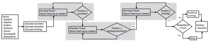
Flowchart of Forward4 My Block
StartPwr, Input, Number, Default Value 0.
MaxPwr, Input, Number, Default Value 60.
EndPwr, Input, Number, Default Value 0.
Distance, Input, Number, Default Value 12.
GyroIn, Input, Number, Default Value 0.
RcvHandoff , Input, Logic, Default Value False.
BrakeAtEnd, Input, Logic, Default Value True.
GyroOut, Output, Number.
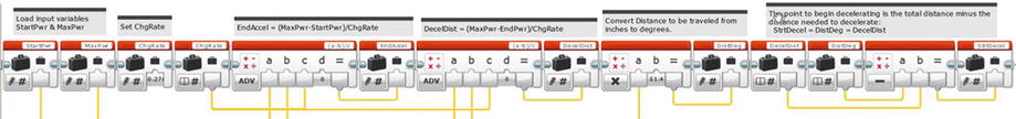
First part of Forward4 , similar to Forward3
The next section of the program will calculate EndAccel, DecelDist, DistDeg, and StrtDecel, then determine whether there is sufficient room for the robot to accelerate and decelerate in the allotted distance.
The variables StartPwr and MaxPwr are used later in the program, so start by defining them. From the Data Operations programming tab, drag a Variable block to the end of the program chain. Name it StartPwr and set its mode to “Write – Numeric.” Click the name box in its upper right corner and select Add Variable . Type StartPwr for the variable name and press Enter. Connect the My Block input StartPwr to its input with a data wire. Repeat the process to create a variable named MaxPwr, also wired to the corresponding My Block input.
Calculating EndAccel, DecelDist, DistDeg, and StrtDecel


“a” Math block parameter: MaxPwr input.
“b” Math block parameter: StartPwr input.
“c” Math block parameter: ChgRate variable.
Add a Variable block to the end of the program chain with mode set to “Write – Numeric.” Click the variable naming box, select “Add Variable,” and create a new variable named EndAccel. Wire the output of the Math block to the input of the EndAccel variable. This is illustrated in the first four blocks of Figure 7-7.

“a” Math block parameter: MaxPwr My Block input.
“b” Math block parameter: EndPwr My Block input.
“c” Math block parameter: ChgRate variable.
As with EndAccel earlier, add a Variable block to the end of the program chain, with mode set to “Write – Numeric.” Click in the variable name box, select “Add Variable ,” and create a new variable named DecelDist. Wire the output of the Math block to the input of the DecelDist variable, as shown in Figure 7-7.
“a” Math block parameter: Distance input.
“b” Math block parameter: 51.4 (or whatever is appropriate to convert inches to degrees of wheel rotation for your robot).
Then, add a Variable block with mode set to “Write – Numeric,” create a new variable named DistDeg, and wire the output of the Math block to its input, as shown in Figure 7-7.

To do this calculation, add two Variable blocks to the program chain with mode set to “Read – Numeric”: one for DecelDist and the other for DistDeg. Then add a Math block configured to Subtract, and another Variable block with mode set to “Write – Numeric” for parameter StrtDecel. Wire the first two variables to the Math block’s input, and the Math block’s output to StrtDecel, as shown in Figure 7-7.
The next task the program needs to perform is to consider the My Block’s input parameters and determine whether they allow enough space to accelerate and decelerate . If there is, the program can continue normally, but what if there is not? How can we know, and how do we deal with that situation?

If this condition is true, then the program can continue operating. Otherwise, as shown in Figure 7-4(c), there is not enough room and the program must somehow handle an error condition. In this case there are so many different situations that could lead to this error that it is probably wise to just flag it, stop the program, and let the user make appropriate adjustments to the My Block parameters.
To determine if there is enough room to accelerate and decelerate , we sum EndAccel and DecelDist, calculate DistDeg, compare those two numbers, and output a logic value to a Switch block. In the True branch of the Switch block, the program will continue normal operation. In the False branch it will flag an error and stop execution. Next, we add blocks to implement these steps.

Determining if there is enough room to accelerate and decelerate
Add a Variable block for DistDeg next, with mode set to “Read – Numeric,” followed by a Compare block with mode set to “Greater Than or Equal To.” This block will perform the test to determine if there is enough room to accelerate and decelerate . Connect the DistDeg Variable block output to the Compare block “a” parameter input with a data wire. Connect the “Add” Math block, the output of which is EndAccel+DecelDist, to the Compare block “b” parameter input. Finally, add a Switch block to the program chain, with mode set to Logic, and connect the Compare block output to the Switch block input with a data wire, as shown in Figure 7-8.
The True branch of the Switch block will contain instructions to make the robot accelerate, maintain speed as needed, and decelerate . The False branch of the Switch block will contain code to handle situations when there is not enough room to accelerate and decelerate fully. Let’s deal with the False branch first. When there is not enough room to accelerate and decelerate, we need to provide clear feedback to the user and terminate the program early. The feedback will take two forms: The brick status light will turn red and an error message will be displayed. We will also turn off the drive motors before exiting the Switch block.

Code to turn brick status light red, stop motors, and output error message

Error message
Clear Screen: True.
x: 0.
y: 0.
Color: False.
Font: 2.
Add four more Display blocks to the program chain with all of their modes set to “Text – Grid,” Clear Screen and Color set to “False,” x set to “2” (to indent the error description), and Font set to “2.” For the first one set the Text to “Not enough” and y to “3”; the second block’s Text to “room to” and y to “5”; the third block’s Text to “accel and” and y to “7”; and the last block’s Text to “decel.” and y to “9.” The code in the False branch of the Switch block should look something like Figure 7-9.
As depicted in Figure 7-5, when the program is operating normally the next phases will be to accelerate to top speed, maintain that speed if needed, and decelerate to final speed. The same code can be used for all three functions, making it perfect for a My Block. This My Block will need three inputs: starting power, acceleration or deceleration rate, and distance at which to stop accelerating or decelerating.
Start of ChgFwdSpd My Block


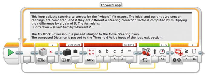
First part of loop in ChgFwdSpd My Block
ChgFwdSpd My Block
There is a new issue that might show up in the ChgFwdSpd My Block. Recall that we tuned the gain in Forward3 using a relatively low power (~30 percent) for the drive motors to prevent wheel slippage. If the robot tracks well and the steering is stable across a wide range of speeds, a fixed gain is fine. If the robot does not track well or it exhibits steering oscillations at some speeds, it might be appropriate to vary the gain with speed: higher gain for higher speeds, lower gain for lower speeds. A Math block, inserted after the Math block that computes drive motor power, can do this. Set the Math block to Divide mode, connect the computed motor power to the “a” input, and set the “b” input to a value that allows the robot to track without steering oscillations. For my robot a value of 15 worked well. A little experimentation should reveal a value that works for your robot.

Blocks in Forward4 to accelerate

Blocks in Forward4 to maintain top speed
Blocks in Forward4 to decelerate
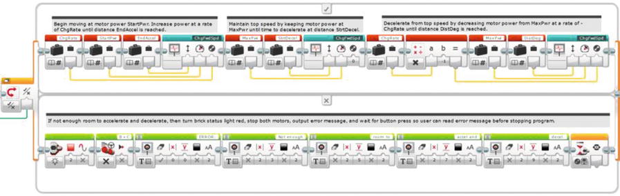
Switch block to accelerate and decelerate (True branch) or stop robot and indicate error (False branch)
Only two things remain: stopping both motors if BrakeAtEnd is True, and outputting the value of GyroStart (to the My Block output GyroOut) in case there is another My Block following Forward4 .
First insert a variable block at the very beginning of the program with mode set to “Write –Logic,” and set the variable name to BrakeAtEnd. Wire the My Block input BrakeAtEnd to this variable. Note that although they have the same name, the My Block input parameter BrakeAtEnd is not the same as the variable BrakeAtEnd, which is why the former must be wired to the latter.

Last part of Forward4 My Block
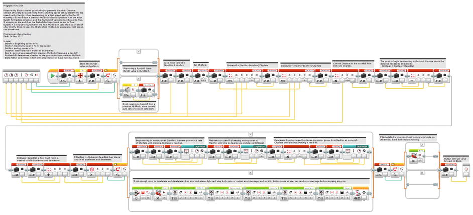
Forward4 My Block
Adding Handoffs to LineFind
Learning topics covered: My Blocks, feedback , looping constructs , conditional constructs
Handoffs at speed are probably most useful when transitioning from one type of My Block to another. For instance, the black lines on a competition mat can be very useful as is, but what if one wants to find a line and keep moving, instead of stopping? If the handoff feature implemented in the earlier My Blocks is implemented in the LineFind My Block, then the robot could move forward until it is close to the line (e.g., using a Forward4 My Block), then find the line to get a position fix (waypoint), and hand off to another Forward4 My Block without ever slowing down. This approach would not only eliminate wasted time stopping and starting, but also allow the robot to move at a relatively high speed, saving even more time. Let’s modify the LineFind My Block to incorporate handoffs at speed.
Begin by copying the FindWhite and FindBlack loops from LineFind and pasting them into a new program. Next, copy the first three blocks (Motor Rotation, GyroStart Variable , and Switch blocks) from Forward3 and insert them just before the FindWhite loop in the new program.
Because the robot will sometimes continue moving after it finds the black line, it will be helpful to have some user feedback to indicate whether the robot detects the line when it passes over it. We can do this by changing the brick status light to a different color. From the Action tab, drag a Brick Status Light block to the end of the program chain, right after the FindBlack loop . Set its mode to On, Color to 1 (orange), and Pulse to False. As this block is almost at the end of the program, you will need to leave the light on or it will flash so quickly that it will not be noticeable. This means that the calling program (the program that contains this My Block) will have to turn it back to flashing green. We will return to that after we finish the My Block.
BrakeAtEnd: Input, Logic, default True.
Port: Input, Number, default 1.
Power: Input, Number, default 30.
RcvHandoff : Input, Logic, default False.
GyroIn: Input, Number, default 0.
GyroOut: Output, Number.
GyroIn to the first GyroStart variable block .
RcvHandoff to the input of the first Switch block.
Power to the Power input of each Move Steering block.
Port to the Port input of each Loop block.
BrakeAtEnd to the input of the last Switch block.
The output of the final GyroStart Variable block to the GyroOut output of the My Block.
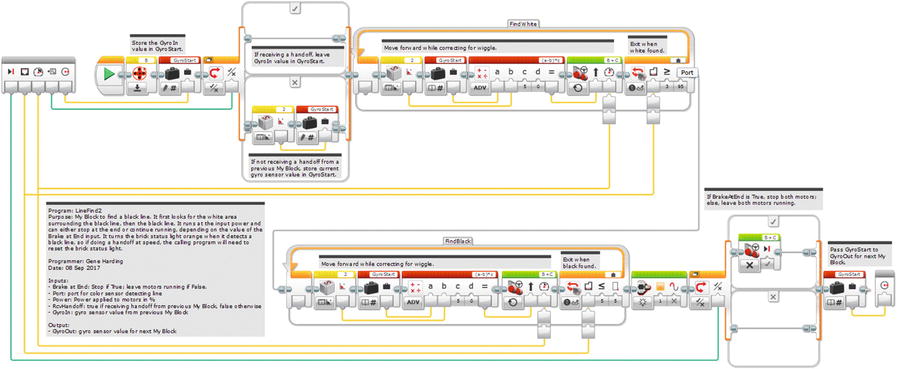
LineFind2 My Block with handoff capability
Now, let’s write a brief test program to make sure the handoff function works properly, and to see how to handle the orange light. Recall that the brick status light normally flashes green while a program is running. A good practice for dealing with the light is to add code to the calling program that leaves the light orange for a second or two, then changes it back to flashing green. That way you will know that the program is operating normally until the status light is changed to orange or red by another program block.
First Forward4: StartPwr 20, MaxPwr 100, EndPwr 100, Distance 12, GyroIn 0, RcvHandoff False, BrakeAtEnd False, and wire GyroOut to the GyroIn input of the LineFind2 My Block.
LineFind2: BrakeAtEnd False, Port 1 (or whatever port is used for the color sensor), Power 100, RcvHandoff True, and wire GyroOut to the GyroIn input of the last Forward4 My Block.
Last Forward4 : StartPwr 100, MaxPwr 100, EndPwr 20, Distance 8, RcvHandoff True, and BrakeAtEnd True.
Wait block : Mode Time, Seconds 1 (or 2).
Brick Status Light block: Mode On, Color 0 (green), Pulse True.
Wait block: Mode Time, Seconds 2.

Handoff test program
The approach used in this section can be used to add Handoffs to other programs, such as LineFollow , LineTFind , WallFollow , and WallLean . Once you do this you will have a fairly complete and potent suite of My Blocks to enable navigation to pretty much any point on the game board, allowing you to focus more on the mission programming.
Combo Program
Learning topics covered: My Blocks, looping constructs , conditional constructs
For competition, it is normally most effective to combine multiple missions together into a “mission set” on the game board so that a single program can accomplish them before the robot returns to base. Once back in base, the two team members at the table reconfigure the robot by changing attachments and selecting a different program to execute the next mission set. Selecting the next program requires scrolling up or down to the correct program, which usually takes a few seconds and occasionally leads to an error (selecting the wrong program). Wouldn’t it be nice if there was a way to avoid that error-prone selection process and save a few seconds at the same time?
Toward the end of our last season, my son, Graham, came up with a really cool idea we called the Combo program, so this section is dedicated to him. The concept uses a Switch block inside of a Loop block. The Loop block is in Unlimited mode, so once the program starts it runs continuously until stopped by the user. The Switch block is in mode Brick Buttons – Measure, which means it executes a different branch dependent on which button is pressed on the brick. Each mission program is converted to a My Block and inserted into a different branch of the Switch block. The default branch contains no blocks, so it does nothing but loop, waiting for the user to press a button on the brick. Because the brick has five buttons, this approach should work for up to five different mission sets.
I should note that we tried to implement this program near the end of the season, were not immediately successful, and decided to abandon it because we were so close to competition. It was not clear whether it did not work because we were doing something wrong or because the mission programs were so complex that the brick could not handle them being converted to My Blocks and executed inside a Switch block inside a Loop block. Theoretically, it should work fine, and the program I describe here worked well, but the My Blocks in this program are very small and simple compared to what the kids were running in competition. Nevertheless, if you want to try it, here’s how.

Switch block controls and indicators

Combo program
Conclusion
If you have successfully implemented the My Blocks described in this chapter, you should have a powerful suite of My Blocks to help your robot navigate quickly and accurately on a game board. Next, the final chapter moves away from programming to discuss several topics related to building and managing a team, preparing for competition, and competing.