Learning Topics
My Blocks, unit conversion, feedback, looping constructs, proportional control, variables, and conditional constructs
Requirements
- 1.
Find a black line when crossing it.
- 2.
Follow the right or left edge of a black line a specified distance.
- 3.
Find the point at which a black line makes an abrupt 90° change in direction.
- 4.
Square up on a black line.
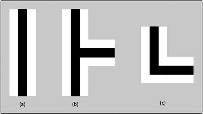
Line, line-T, and line-L
The color sensor has several different modes, most of which deal with detecting either a color , reflected light intensity, or ambient light intensity . Color sensing is covered here for completeness, but the focus in this chapter is dealing with black and white lines.
When used in a color-sensing mode the sensor can measure the following colors: no color (0), black (1), blue (2), green (3), yellow (4), red (5), white (6), or brown (7), outputting the numeric value listed in parentheses corresponding to the detected color. It can also compare the numeric value of the detected color to a given value, outputting both a logic result of the comparison and a numeric result for the color detected.
The color sensor can measure either reflected light intensity or ambient light intensity, outputting numeric values ranging from 0 (minimum reflected light) to 100 (maximum reflected light). When measuring reflected light intensity, the red light-emitting diode (LED) inside the sensor shines light downward, and the sensor detects how much light is reflected back. When measuring ambient light intensity , the LED remains off, so only ambient light is detected (i.e., light from other sources, such as lamps or overhead lights in the room or sun shining through the window). The sensor can also compare either reflected light intensity or ambient light intensity . In these modes it still outputs the numeric value of light intensity measurement, but also outputs a logic value corresponding to the result of the comparison.
In each of the Compare and Measure modes just listed, the sensor’s sample rate is 1 kHz, or 1,000 samples per second (EV3 User Guide, either Home or Education Edition).
Finally, the color sensor has Calibrate modes . If a guard is built around the sensor to prevent ambient light from entering, the Calibrate modes might not be needed. On the other hand, if a guard is not in place to shield it and only one sensor is used for line following, calibrating the sensor is very important. The next section addresses calibrating the color sensor for different ambient light conditions.
Calibrating the Color Sensor
Learning topics covered: calibration, feedback , looping constructs
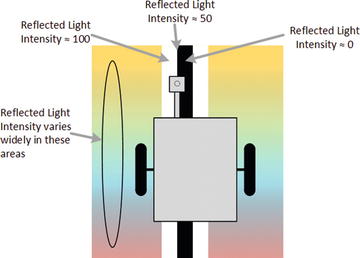
In Reflected Light Intensity mode , the EV3 color sensor can return values ranging from 0 to 100. A 0 value indicates no reflected light, corresponding to a surface so dark that none of the LED’s light is reflected into the sensor. A value of 100 indicates “full” reflection, or a surface so bright that it reflects essentially all of the LED’s light into the sensor. In most situations, the range of sensor values will not be 0 to 100, but instead a smaller range. For example, suppose that a given competition mat with a certain amount of ambient lighting results in a light intensity value of 9 over a black line (dark surface) and a 93 over a white line (reflective surface). The problem is that different levels of ambient lighting can change these maximum and minimum values, so a given program can operate differently in different environments. My teams have seen their programs operate differently as the sun changed position in the sky, shining more or less light into the room through the windows.
Calibration can deal with this problem by redefining what constitutes a value of 0 or 100. For instance, in the scenario described earlier, the robot could be calibrated to treat a 9 as a 0 value, and a 93 as 100. By recalibrating the robot whenever the environment changes, you can reduce or eliminate the impact of a change in ambient light conditions. My teams found calibration to be critical when using a robot with no guard, or shielding, around the light sensor(s), so we always calibrated the robot just before doing a formal mission set run. We later built a guard to go around the light sensors to block ambient light. Although the guard seemed to eliminate the need for regular calibration, we continued the practice just to be safe.
There are three Calibrate modes , all dealing with reflected light intensity. The Minimum mode redefines what constitutes a 0 value; the Maximum mode redefines what constitutes a value of 100; and the Reset mode changes back to the default values. Let’s start with a basic calibration program.
- 1.
Reset the sensor .
- 2.
Place the robot so its light sensor is over a black line.
- 3.
Read the sensor value and pass it to the Calibrate Minimum block.
- 4.
Place the robot so its light sensor is over a white line.
- 5.
Read the sensor value and pass it to the Calibrate Maximum block.
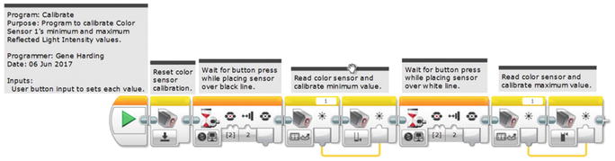
Calibrate program
This approach works, but there is a significant issue with it: There is no way of being sure that the light sensor is placed so that it reads the desired minimum or maximum value. We address that issue by using feedback and a couple of loops.
Copy Calibrate to a new program and name it Calibrate2. We will use a loop to continuously poll the color sensor and display its value so we know when it is at a minimum or maximum. Replace the Wait blocks with Loop blocks . Set each loop exit mode to Brick Buttons, and pick the button of your choice. Note that when using the buttons in this manner, using the “bumped” option (2) is probably the most reliable choice. Sometimes one press or release can trigger the exit for multiple loops, even though it should not do so. Give a meaningful name to each loop, such as DisplayMin for the first loop and DisplayMax for the second. Place a Color Sensor block followed by two Display blocks (from the Action Blocks tab) inside each loop. Configure both Color Sensor blocks in “Measure – Reflected Light Intensity ” mode. The Display blocks will present a user prompt and display the current light intensity value.

Calibrate2 program
The second loop will be similar, but not the same as the first. To leave the Minimum value displayed, set the Clear Screen parameter of both Display blocks to False. Set the prompt text to “Max?,” Column to 0, and Row to 4 so it will display at the start of a new line. As with the DisplayMin loop, select the “Wired” option and wire the output of the Color Sensor block to the Text input of the second Display block. Set the Column parameter to 12 and Row to 4.
One tip here is very important: Add several spaces to the end of the “Max?” prompt so that the numeric value is cleared each time the loop executes. This is important to avoid confusing readouts. For instance, suppose the sensor is placed over a white area and returns a value of 100, then is moved to a shaded area where it returns a value of 25. If the old value is not cleared (with the extra spaces), the 2 will overwrite the 1 digit of 100, the 5 will overwrite the first 0 digit of 100, and the second 0 digit of 100 will remain, so it will look like the value being displayed is 250 instead of 25.
Note in Figure 5-3 that the program chain has been split into two rows. Arranging programs in this manner often improves readability, so let’s try it. Select the second loop and the blocks that follow it, and drag them down and to the left so they are under the first loop. Then, “grab” the Sequence Plug Exit of the top right Color Sensor block and connect it to the Sequence Plug Entry of the second loop. Remember to add appropriate comments, then save and try out the Calibrate program.
Finding a Black Line
Learning topics covered: My Blocks, feedback , looping constructs
- 1.
Use dead reckoning to get close to the line.
- 2.
Look for the white space before the black line.
- 3.
Look for the black line itself.
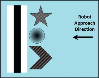
Dark areas adjacent to black line

Program to find white area
A second loop is needed to find the black line, so copy the loop FindWhite, paste it right after the first one, and rename it FindBlack. Because the goal is to find black, which reflects very little light, the loop exit criterion will be to a light intensity less than a low value, probably somewhere between 5 and 15. Change the Compare Type parameter for the loop to 5 (≤) and enter a low threshold value. Add a black line to the white piece of paper and test the program.

My Block to find a black line
Following a Black Line
Learning topics covered: My Blocks, unit conversion , feedback , looping constructs , proportional control
Line following concept
Now, think about what happens if the robot drifts to the left: The sensor is over more of the white line and less of the black line, which means the Reflected Light Intensity value increases to somewhere in the range of 51 to 100. After subtracting 50 the value is still positive, and a positive Steering value causes the robot to steer to the right, back toward the edge of the black line. Likewise, if the robot drifts to the right, the Reflected Light Intensity value decreases, and after subtracting 50 the value will be negative, which will cause the robot to steer left, back toward the edge of the black line.
Remember the proportional control technique described in Chapter 3 for wiggle control? This is the same control technique because the farther the robot drifts from the edge of the black line, the higher the steering correction to move it back. In this case, however, there is one more thing to consider: sensor placement. It might make sense to think of the robot as following the color sensor, so the sensor must be ahead of the driving wheels by at least a couple of inches, and preferably 3" to 5" inches or so. If the color sensor is placed too close to the driving wheels, it will be difficult or impossible to get the robot to follow the line smoothly.
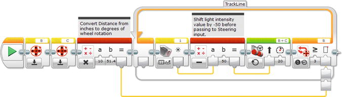
Initial line following program

To start, set c = 0.5 and d = 1.0, change the power back to 20, then run the program again. Change d to –1.0 and verify that the robot follows the left edge of the black line. Spend some time experimenting with values for gain (c input) and the Power input to the Move Steering block to get a feel for how they affect the line following performance. For a given speed, higher values of gain will allow the robot to track the edge of the line even if it is not initially aligned with it, but it will also tend to oscillate. Thus, there is a trade-off between smoothness and ability to track the line when approaching from an angle.
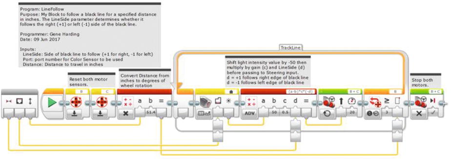
LineFollow My Block
Finding Black Line Intersections (Ts and Ls)
Learning topics covered: My Blocks, feedback , looping constructs
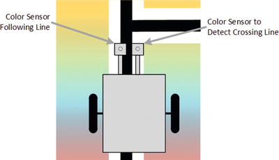
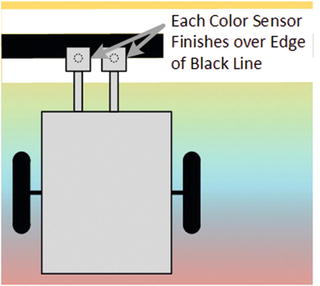
Using two color sensors to find line intersections
Performance will be more consistent if the color sensors are matched. Run the Calibrate2 My Block with the Port set to 1 in all four of the Color Sensor blocks, making a note of the minimum and maximum calibration values. Repeat with the Port set to 3 (or whichever port your other color sensor is using). If both values are within a few percent of each other, it should be fine. If not, it might be worth some effort to track down a color sensor that is a closer match to one of them.
The LineFollow My Block from the previous section is the basis for the LineTFind My Block . The inputs will be a little different, so a new My Block must be created from scratch. Start by copying LineFollow to a new program, then deleting the three blocks before the loop . These blocks will not be needed because the robot will keep going until it finds the intersecting line, regardless of the distance. The loop exit condition must also be modified to look for a light condition. Change its mode from “Motor Rotation – Compare – Degrees” to “Color Sensor – Compare – Reflected Light Intensity ”, and set the condition to 5 (≤).
There are now two sensor ports being used, but the side of the line to follow will determine which port is used to follow the line and which is used to find the intersecting line, so no port input(s) are needed. Create the LineTFind My Block with one numeric input called LineSide. Insert a Switch block before the loop, set its mode to “Numeric,” and connect the LineSide input to it. On my robot, the left color sensor uses port 1 and the right sensor uses port 3, so if the input is 1 the robot will use port 3 to follow the right side of the line and port 1 to find the intersecting line. If the input is –1 the port assignments must be reversed.
We need two new variables to hold the port values, so create those variables, name them “FollowPrt” and “FindPort,” or something that makes sense to you, and place one of each in the top part of the Switch block (in “Write – Numeric” mode), and one of each in the bottom part of the Switch block. (The reason for naming the first one “FollowPrt” instead of “FollowPort” is so the full name will be displayed when the variable appears in the program. If it is named “FollowPort” then “FollowP…” appears as the variable name because there is not enough space for the full name. If you cannot see the full variable name, just abbreviate it until you can. You can delete unused variables in the Project Properties window.)
The top value of the Switch block can stay at 1, but the bottom part must be changed from 0 to –1. Note that the “dot” selection next to the 1 at the top indicates the default, so if the input is any value other than –1 the Switch block will execute the top portion. When the input is 1, FollowPrt should be 3 and FindPort should be 1, and vice versa when the input is –1.
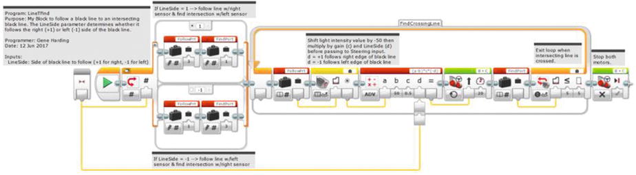
LineTFind My Block
Squaring Up on Lines
Learning topics covered: My Blocks, feedback , looping constructs
Squaring up on a line
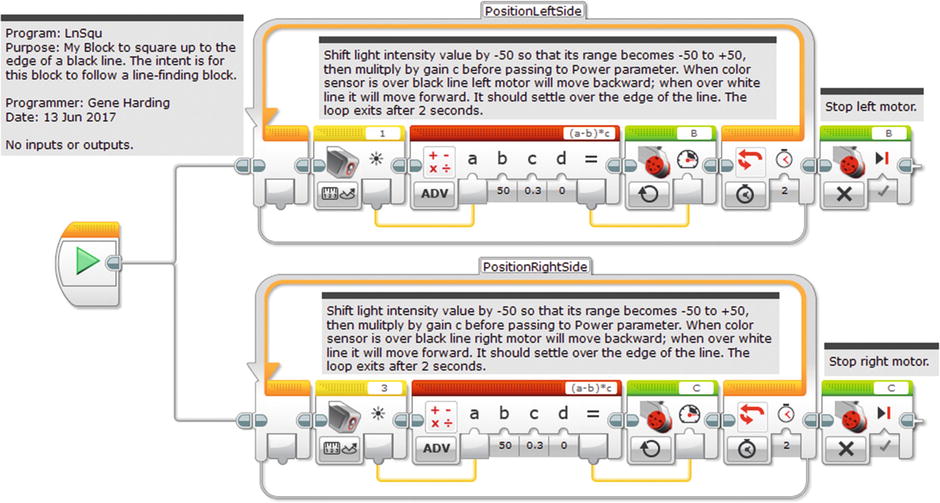
LnSqu (line-squaring) My Block
Conclusion
You should now have a suite of several My Blocks that use lines to improve navigation accuracy. Using lines can make a very substantial difference, often the difference between success and failure on a given mission or set of missions. Walls can be used in a similar fashion to aid navigation, and that is the subject of the next chapter.