4
STM Project Development
In this chapter I will demonstrate how to build C/C++ language projects with a STM Nucleo board using the toolchain created in Chapter 2 and the CubeMX application described in Chapter 3. I will be using C/C++ language to create the source code for these projects. It would be helpful, but not really required, if readers are somewhat familiar with the C/C++ language in order to achieve a better understanding of the entire process. I will go thoroughly into the example code for the “Hello World” project to help clarify what is happening with the source code for those readers who are not too proficient in using C.
Hello World Project
The traditional and customary “Hello World” program is the one that beginning developers almost always make when starting their computer language studies. In the embedded world, this program has morphed into blinking an LED instead of displaying “Hello World!” on a monitor screen. I will demonstrate step-by-step how to create a “Hello World” project using a Nucleo64-STMF302R8 demonstration board connected to a Windows 10-based host system running the toolchain established in Chapter 2. You will not benefit much from this chapter unless you have read the previous chapters and created a working toolchain and become somewhat comfortable using the CubeMX application.
Creating the Hello Nucleo Project
The first step in creating a project is to open CubeMX application. Once the application is started, click on New Project and click on the Board tab. Select the Nucleo board that you are using. In my case, it is the NUCLEO-F302R8 board, as shown in Figure 4-1.
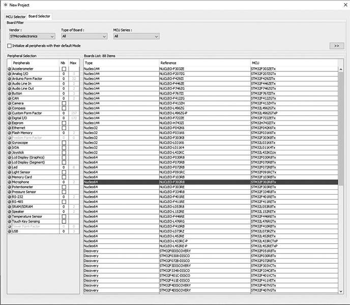
Figure 4-1 New C/C++ Project dialog box.
Next, double-clicking on the board selection line will cause the project pinout screen shown in Figure 4-2 to be displayed.
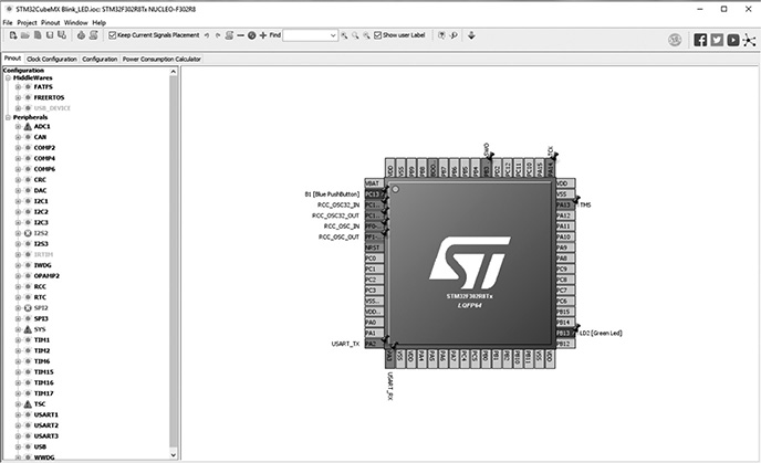
Figure 4-2 Project pinout screen.
The next step is to click on the Project menu item, which will result in the dropdown menu, as shown in Figure 4-3.
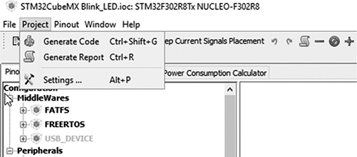
Figure 4-3 Project dropdown menu.
Clicking on the Generate Code selection will cause the Project Settings dialog box appear, as shown in Figure 4-4.
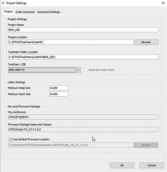
Figure 4-4 Project Settings dialog box.
You need to provide a name in the Project Name textbox. It should be something relevant to the intended project purpose. Also confirm that the Project Location is correct along with the Toolchain Folder Location.
It is very important that you select the MDK-ARM V4 from the Toolchain/IDE combo list. The project cannot be created without MDK-ARM V4 selection.
The default Linker Settings should be okay and the “Mcu and Firmware Package” and “Firmware Package Name and Version” should also be similar to what is shown in the figure.
Finally, ensure that the checkbox next to “Use Default Firmware Location” is checked, otherwise the IDE will not be able to create the binary file.
Do NOT click on the Ok button, but instead click on the Code Generator tab near the top of the dialog box. This should make the Project Settings/Code Generator dialog box appear, as shown in Figure 4-5.
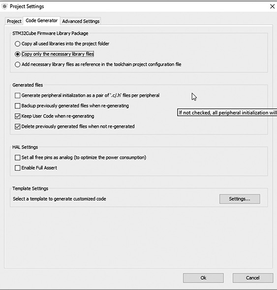
Figure 4-5 Project Settings/Code Generator dialog box.
The radio button next to “Copy all used libraries into the project folder” will initially be selected. You should click on the radio button next to “Copy only the necessary library files” in order to minimize the size of the overall project. Neglecting to make this change will not affect the size of the final binary file, but will needlessly enlarge the project folder size.
Now you can click on the Ok button to have the CubeMX application automatically generate the C/C++ code.
After a short interval, a successful Code Generation dialog box should appear, as shown in Figure 4-6.
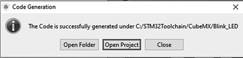
Figure 4-6 Successful Code Generation dialog box.
Clicking on the Open Project button will cause the Keil IDE to be opened with the newly created project shown in the Project pane to the left side of the window, as shown in Figure 4-7.
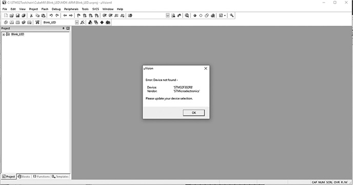
Figure 4-7 Keil IDE with the new project.
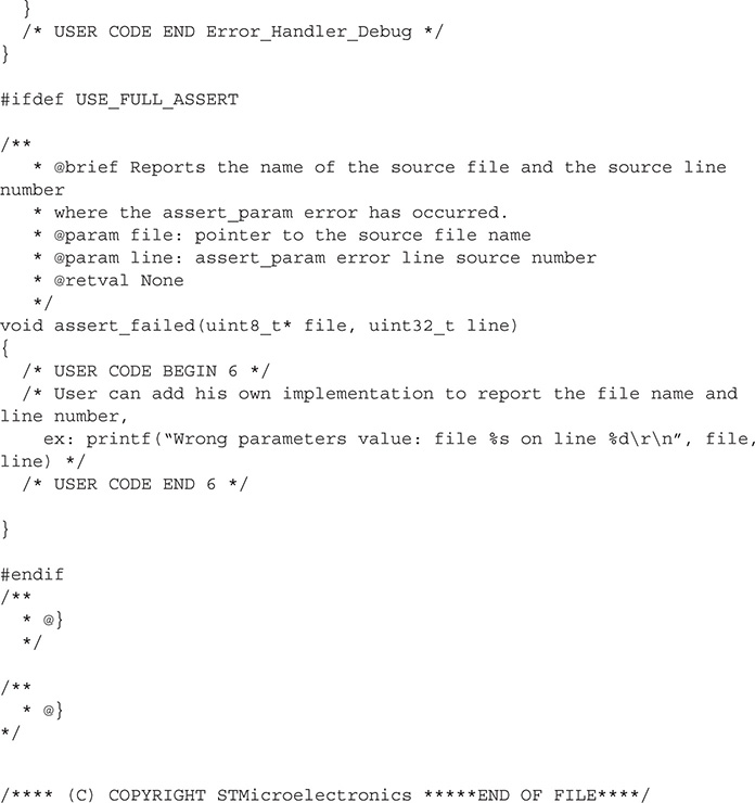
The error dialog that appears in Figure 4-7 has been discussed in the previous chapter and is due to the IDE not having a reference to the real target hardware. That is easily fixed by going to the Device Database, as described in Chapter 3. Once that is resolved, you should expand the Project directory by clicking on the + check box. Once expanded, click on the dropdown arrow next to the Application/User subdirectory to reveal the files in that directory. Finally, double-click on the main.c file, which will display the following listing. Note that this listing is the same, as has been previously shown in Chapter 3. However, I do this to provide the proper context to make the desired modifications in order to add some functionality into an otherwise nonfunctional program. Also, note that the extensive STM disclaimer commentary has been minimized to save listing space.
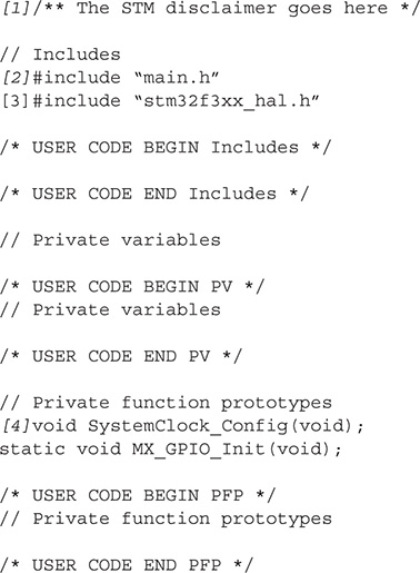
I have chosen to provide commentary to the listing using italicized number annotations to designate those portions of the listing being discussed. Simply refer to the listing and the associated number in italics to keep track of the discussion topic.
[1]—Either the /* ... */ or // designate a commented line, which is ignored by the compiler. The first format allows for multiple comment lines, while the second is only for a single line. Comments are for human use as a means for the developer to explain what is happening within the source code. I strongly recommend that you always comment your programs as you see with this listing.
[2]—The # symbol indicates a compiler instruction or directive immediately follows. In this case the statement is #include “main.h” which instructs the compiler to use a header file named main.h. This particular header file is stored in a workspace header file directory because the header file name is enclosed by double quotes. The main.h contains constants, definitions, and functions that provide “understandable” names to general-purpose input/output (GPIO) pins such as LD2 for the user LED and Push Button for the user push button.
[3]—This header file provides all the required constants and definitions for the project code to utilize the HAL framework.
[4]—All methods that are called must be declared prior to use in the C/C++ language. That is the purpose of the prototype section.
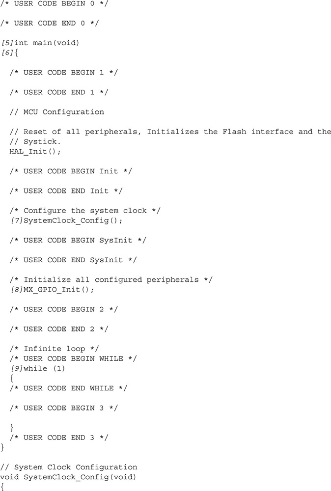
[5]—This is the starting point for the program. The int in front of the main function name indicates that the main function returns an integer value. This returned value to the operating system is normally a 0 if the program terminated normally, otherwise a 1 is typically returned.
The function arguments
![]()
are used only when starting values are to be supplied to the program before it starts to execute. In this case, they are not required.
[6]—This is the opening brace. All C/C++ functions enclose all their code between opening and closing braces. There must be a matching closing brace for this main function or else the C/C++ compiler will generate an error.
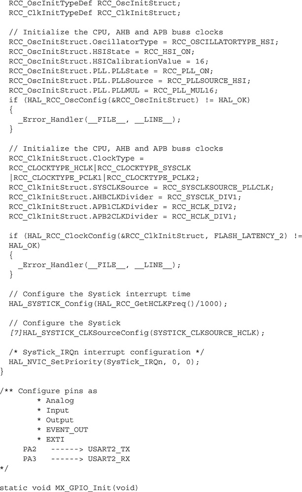
[7]—This statement starts a system timer that generates a SysTick every 1 ms. Note the statement ends with a semicolon, which is normally required for all C/C++ declarative statements. Omitting semicolons is a common mistake done by beginning (and not so beginning) developers.
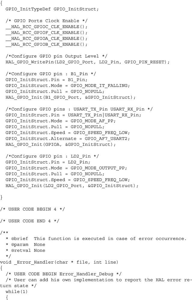
[8]—This statement initializes the appropriate GPIO pin that directly controls the user LED. In this case, the GPIO pin is PA5, meaning it is one of the eight pins found in port A. There are multiple GPIO ports in STM MCUs. The exact amount depends on the particular model.
[9]—This is the start of an infinite loop, meaning the program will run forever until manually stopped or having the power disconnected. The 1 in the parenthesis indicates a true value. Often, developers will use a Boolean variable instead of a fixed constant, thus allowing the program to be stopped programmatically from within the scope of the while construct. This scope is determined by opening and closing braces, similar to what was used with the main function. This use of multiple brace pairs is known as nesting.
I will provide additional explanations regarding the code modifications.
I hope that this brief review of the main.c source code has provided you a little insight into how a C/C++ program functions.
Adding Functionality to the Program
I will show you how to add a very simple function to this program, which will flash the onboard green user LED at a rate of once per second. The two statements to be added are shown in the following code snippet, which is the forever loop.
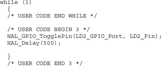
The first statement HAL_GPIO_TogglePin(LD2_GPIO_Port, LD2_Pin); toggles the GPIO pin that is permanently connected to the user LED on the selected Nucleo board. Note the use of human recognizable names for both the GPIO pin connected to the LED and the associated GPIO port. That feature is made possible by the defines contained in the main.h file, which is included in the main.c file.
The second statement HAL_Delay(500); pauses the processor for 500 ms before the LED state changes. This will cause the LED to blink once per second with a 50% duty cycle, meaning it is on for 0.5 s and off for 0.5 s.
Compiling and Executing the Modified Program
Just click on the build icon after you added the additional two statements in the forever loop. Also, ensure you have enabled the hex file output, as described in the previous chapter. This is required prior to using the ST-LINK utility.
Again, follow the ST-LINK detailed instructions provided in Chapter 3 on how to load the hex file and download it into the target board.
The user LED should immediately start to blink once the hex file is downloaded. I am fairly confident that you should have no problem with this procedure given that the program built successfully.
Simple Modification for the main.c Function
The simplest modification to the main.c function is to change the LED timing duration, which is what I have done for this next demonstration. The following code snippet shows the modifications made to the on and off LED timing duration. It was changed to 2 s:
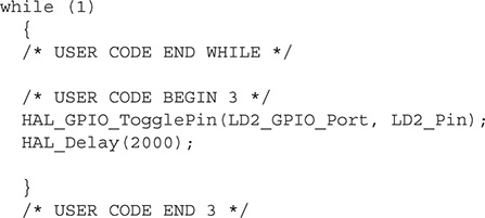
The source code in the main.c file was first changed and then saved. I then rebuilt the project, which in turn generated a new hex file. This hex new file was then loaded into the ST-LINK utility and subsequently downloaded into the Nucleo board using the process I previously described. I immediately observed that the user LED was then flashing at a rate of 2 s on and 2 s off after the new hex file was downloaded into the target.
Complex Modification for the main.c File
The next demonstration is a bit more complex than the previous one in that I want to show you how to blink the LED with different on and off times. I will still be using the user LED LD2 as the light source but will modify the main.c file to incorporate two different timing intervals.
I choose to use several define statements to create different on and off durations for the LED. The main function also uses an if/else statement that causes the on and off intervals to alternate based on the truth value of a Boolean variable named sw. The following is the code snippet for the modified portion of the main.c file:

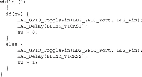
After the main.c file was modified, the project was built in the manner previously described and the resultant hex file was downloaded into the Nucleo board using the ST-LINK utility. The user LED immediately started blinking on for 0.5 s and off for 1.5 s for a net 2-s blink rate. The on and off durations may easily be modified by changing the appropriate define statements.
This last demonstration project concludes this initial discussion on how to create and modify embedded software projects for a STM Nucleo-64 board. The next chapter explores how to use additional GPIOs and the use of interrupts, which will greatly expand the capabilities of the Nucleo board.
Summary
This chapter contains three demonstration C/C++ language projects that all blinked an on-board LED installed on a Nucleo64-STM32F302R8 board. Each project progressed in complexity from an extremely simple constant rate LED flashing to a more complex multi-interval flashing of the LED.
I explained using a step-by-step approach how to conduct a project build. The final hex file created by the build process was downloaded into the Nucleo-64 board using the ST-LINK utility.
A brief discussion of how a C/C++ main function works was also presented for readers who might be a bit “rusty” on their C/C++ language prowess.