7
Timers
Timer peripherals are very important components within a MCU. Many embedded applications are time or temporal dependent and timers are the primary means by which the MCU controls the application. While it is certainly possible to use a MCU to directly time processes, it would be great waste of processing power and highly inefficient approach. Using hardware timers along with interrupts is really the only practical way to implement embedded time-dependent applications. Fortunately, there is a powerful timer variety provided by STM in its line of MCUs.
STM Timer Peripherals
A timer is simply a free-running counter that counts pulses from a clock source. Since the pulse train from a clock source has a known period or interval between pulses, the elapsed time is directly related to the number of pulses counted. The timer clock source used with a typical MCU is usually derived from an internal master clock. However, the master clock usually runs at a very fast speed, so timer pulses must be divided by hardware to more reasonable values that can be used by timers. The hardware used to “slow” the master clock rate varies and can be binary dividers (prescaler) or phase-locked loops (PLL). Timer counters can count up or accumulate counts until they overflow based on the number of bits used in the counter. A 16-bit counter will overflow when the maximum count of 65535 is reached. An overflow interrupt is often the event which happens with this situation.
Conversely, a timer counter can count down from some preset value and trigger an interrupt when it reaches a 0 value. This counter type is known as a decrementing counter and has many uses.
Timers have many uses, including but not limited to the following:
• Generating a precise time base. All STM timers can do this.
• Measuring the frequency of an incoming digital pulse train.
• Measuring elapsed time on an output signal. This is called output compare for STM timers.
• Generating precise pulse-width modulation (PWM) signals used for servo and motor control.
• Generating single pulse with programmable length and delay characteristics.
• Generating periodic direct memory access (DMA) signals in response to update, trigger, input capture, and output compare events.
There are following five broad categories of STM timers:
• Basic: Simple 16-bit timers. They do not have inputs or output pins. They are principally used as “masters” for other timers. They also are used as a digital-to-analog converter (DAC) clock source. They can generate a time base like all STM timers can do.
• General purpose (GP): These are 16-bit or 32-bit timers with both input and output pins. They can do all of the functions described in the above list. GP timers can have up to four programmable channels, which may be configured as follows:
• One or two channels
• One or two channels with a complementary output. The complementary output has a “dead time” generator, which provides for an independent time base.
• Advanced: All the features of the GP timer with additional functions related to motor control and digital power conversion. There are three complementary outputs available with this timer category with an emergency shutdown input.
• High resolution: Multiple high-resolution outputs made possible by six sub-timers, one master and five slaves. Multiple dead-time insertions are possible with this timer. There are also five fault inputs and 10 external event inputs. This timer has the acronym HRTIM1 in STM terminology.
• Low power: Timers used in exceptional low-power applications. These timers are designed to stay running in just about all STM MCU modes, except the Standby mode. They can even continue to operate without an internal clock source.
The STM32F302R8 MCU used in the demonstration board has basic, GP, and advanced timers. I will focus on how these timers function and are programmed. The concepts discussed will also apply to the other timer types if you encounter them in other projects. As always, the manufacturer datasheets are your best resource to determine how a particular timer works and how it should be programmed.
The STM32F302R8 MCU has six timers, as shown in Table 6-1. This table has a handy reference to keep in mind when selecting and programming a timer.
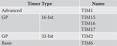
Table 6-1 STM32F302R8 MCU Timers
I will now discuss how to configure a STM timer using the HAL framework.
STM Timer Configuration
STM timers are configured in the same manner as GPIO pins and interrupts as I have previously discussed. STM timers are configured with a C structure named TIM_HandleTypeDef, which contains the following members:
![]()
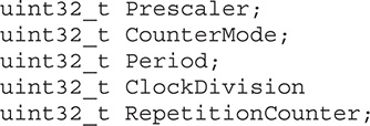
The struct members represent the following timer parameters and settings:
• Prescaler: The division factor used to scale the master clock rate. There are only 16-bit prescalers used in all the timers. A 16-bit register can hold prescaler values ranging from 1 to 65535. For example, a prescaler value of 40,000 applied to an 80-MHz master clock would mean a 2-kHz clock rate would be input into the timer.
• CounterMode: Sets the count direction. The available CounterModes are as follows:
• TIM_COUNTERMODE_UP
• TIM_COUNTERMODE_DOWN
• TIM_COUNTERMODE_CENTERALIGNED1
• TIM_COUNTERMODE_CENTERALIGNED2
• TIM_COUNTERMODE_CENTERALIGNED3
• Period: This is a number that represents the maximum time to be elapsed before the timer counter is reloaded with this number. The maximum number is 0xffff for 16-bit counters and 0xffff ffff for 32-bit counters. A value of 0x0 will ensure a timer does not start.
• ClockDivision: This is a bit-specific field used for setting the ratio between the internal timer clock frequency and a sampling clock used for digital filters. It is also used to set dead-time parameters. The available ClockDivision modes are as follows:
• TIM_CLOCKDIVISION_DIV1
• TIM_CLOCKDIVISION_DIV2
• TIM_CLOCKDIVISION_DIV4
• RepetitionCounter: Sets a limit for the number of times a timer can overflow or underflow. The timer update register will be set when the limit is reached. An event can also be raised in conjunction with the register update.
Update Event Calculation
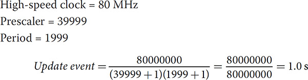
The following equation should be used to compute the time between update events for a given high-speed clock rate, a prescalar value, and a period value:
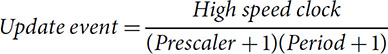
A sample calculation is shown below:
Given:
The discussion on the demonstration project presented below will show you how to configure a GP timer in a polled mode, which in turn will blink an LED.
Polled or Non-interrupt Blink LED Timer Demonstration
This is the first of two demonstrations showing you how to configure the TIM2 GP timer to control LD2, the onboard green LED. This demonstration will not use an interrupt, so I can focus on the discussion of how to configure a timer. The LED will blink at a 0.5-s rate based on the selection of prescaler and period values as well as the Nucleo-64 board’s preset 64-MHz high-speed clock rate.
You should start this project using the CubeMX application by providing an appropriate project name. I used the name TIM2_Example1 for this project. In the Pinout view, you should select the internal high-speed clock as timer TIM2 clock source, which is shown in Figure 7-1.
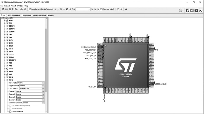
Figure 7-1 TIM2 clock source selection.
Selecting the clock source also triggers the CubeMX application to include all the TIM2 initialization statements to be included in the new project. This step is vital to generate a working project.
Don’t forget that all the other previous project creation steps are still appropriate, such as including only the necessary library files and ensuring that a hex file is generated.
I will discuss the key parts of the project code after the below listing.
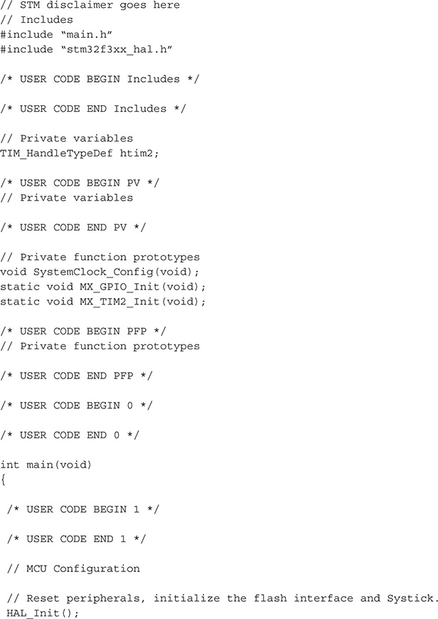
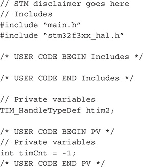
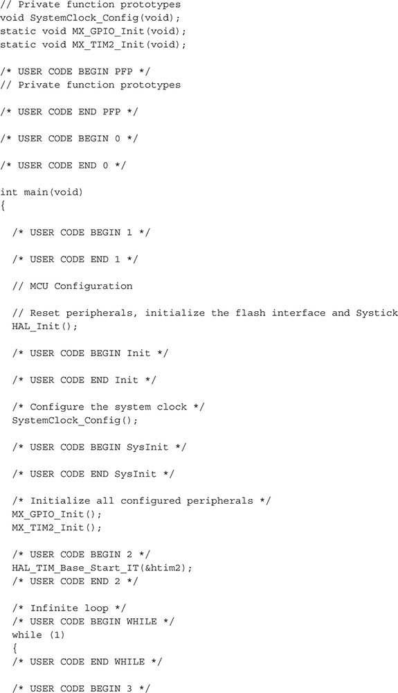
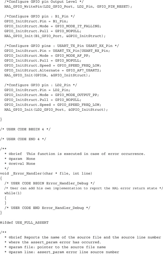
Most of this code is a repeat of the main.c code shown in the interrupt demonstration project discussed in the previous chapter. The key differences are the addition of a MX_GPIO_Init method and some new operational code required in the forever loop portion of the main method.
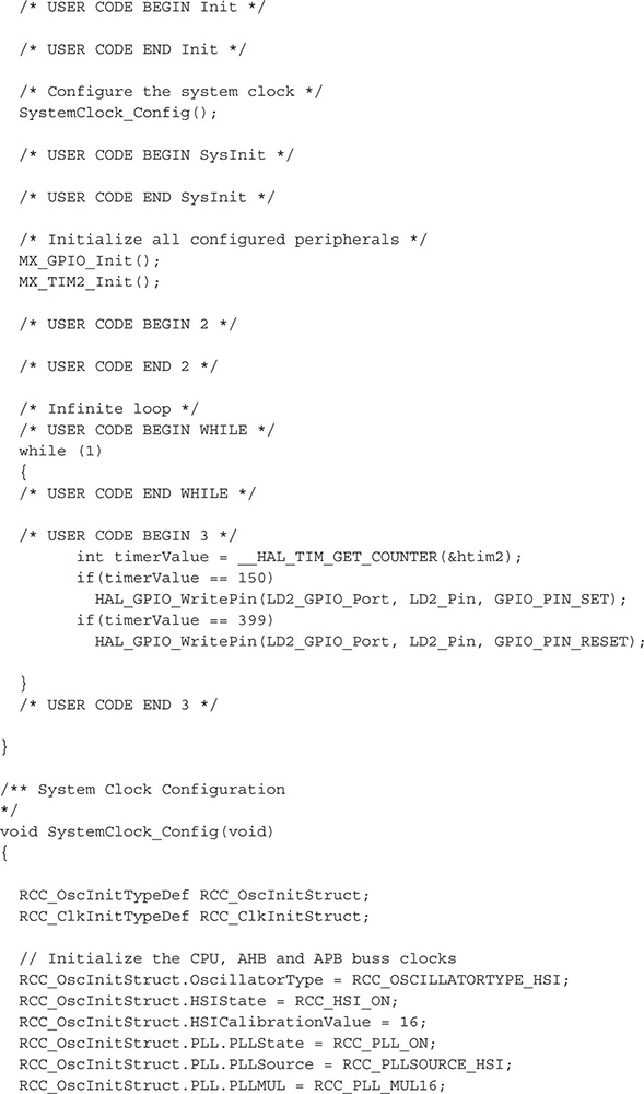
The MX_GPIO_Init method configures the TIM_HandleTypeDef, a typed C struct with specific values to have the timer reset every 0.5 s. The struct is named htim2 and is both initialized and started in this method.
The forever loop in the main method has code, which continually checks the timer count and will turn on the LED when the count reaches 150. It will remain on until the count progresses to a value of 399, at which point the LED will be reset. These statements result in the LED being on for 0.25 s and off for 0.25 s.
Test Run
I built the project and uploaded it into the Nucleo-64 board. The user LED immediately began to blink at a 0.5-s rate, which confirmed the program worked as desired. The next step in this timer demonstration series is to implement an interrupt-driven version that will also blink the LED, but not require any specialized code in the main method’s forever loop.
Interrupt-Driven Blink LED Timer Demonstration
This demonstration will also blink an LED. In this demonstration, I will use an interrupt approach, thus eliminating any specialized code in the forever loop main that continually reads the timer counter value and reacts when certain values are reached.
You will need to generate a new project using the CubeMX application. I named this project Timer_int to reflect its purpose. You will also need to select the timer clock source as has been done in the previous demonstration. Simply use the internal high-speed clock as the source, which will trigger the application to include all the TIM2 timer initialization and configuration code. However, this time you will also have to set up the timer to trigger an interrupt when its period is elapsed. This is easily done using the CubeMX Configuration tab. You should see timer TIM2 appear in the tab, but first ensure you have selected the clock source. Otherwise timer TIM2 will not appear. Click on the TIM2 icon and then click on the enable global interrupt check box. The Configuration tab and the enable global interrupt check box are both shown in Figure 7-2.
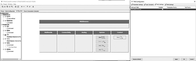
Figure 7-2 Configuring timer TIM2 interrupt functionality.
I will not repeat the extensive code listing previously shown, but will instead just present the code segments needed to implement the interrupt-based code.
The first part is the easy one, where the forever loop is changed to a null action:
while(1);
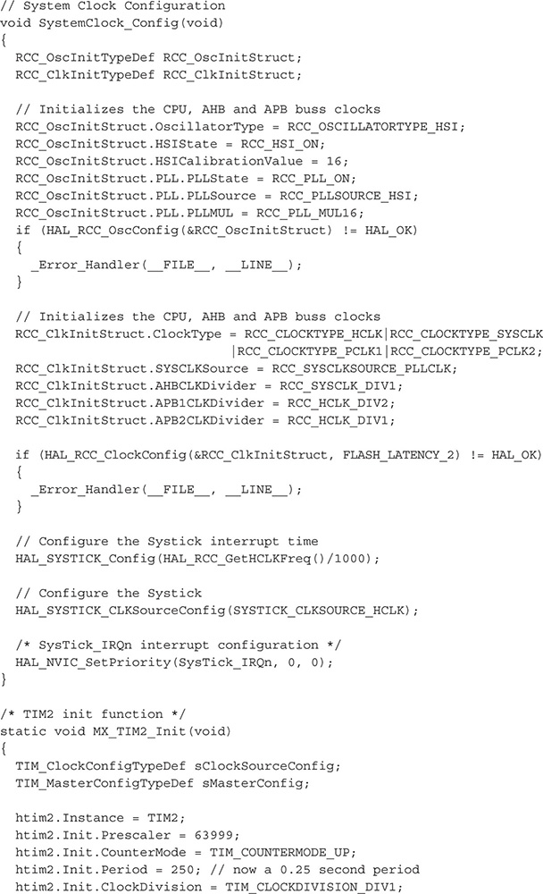
The only other change that needs to be done is to set the timer period to 250 to ensure the LED blinks twice a second. The timer will now interrupt at the appropriate interval without any special code needed to monitor real-time counter values.
The following three statements must be added just before the forever loop in the main method:
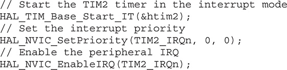
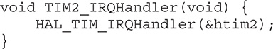
The TIM2 IRQ handler method must be defined in the main.c file as follows:
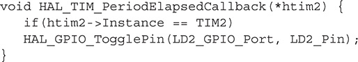
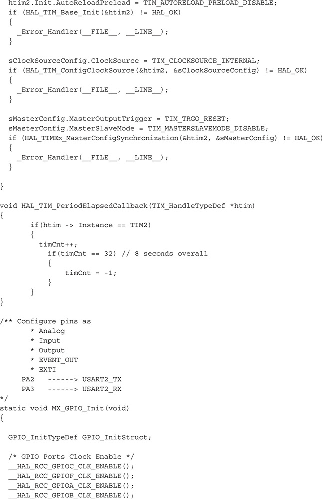
Finally, a callback method must also be defined, which toggles the LED pin every time the TIM2 timer generates an interrupt:
![]()
Test Run
I made the modifications to the main.c file, built the project and then uploaded it into the Nucleo-64 board. The user LED immediately began to blink at a 0.5 second rate, which confirmed the program worked as desired.
Multi-rate Interrupt-Driven Blink LED Timer Demonstration
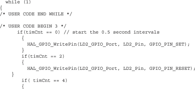
This demonstration is an expansion of the previous demonstration in which the user LED will be repeatedly blinked at two different rates, one at 0.5 s and the other at a 1.0-s rate. A timer interrupt will also be used in this program but with a significant difference between the single- and multi-rate implementations. In the single-rate program, the LED is directly controlled in the callback function. In the multi-rate version, the callback function simply increments a counter variable, which is then used in the forever loop to control the LED. The incrementing counter variable timCnt causes the LED to be set or reset depending on its value. The following listing is the complete main.c listing. I have also added additional comments regarding the forever loop code snippet following the listing.
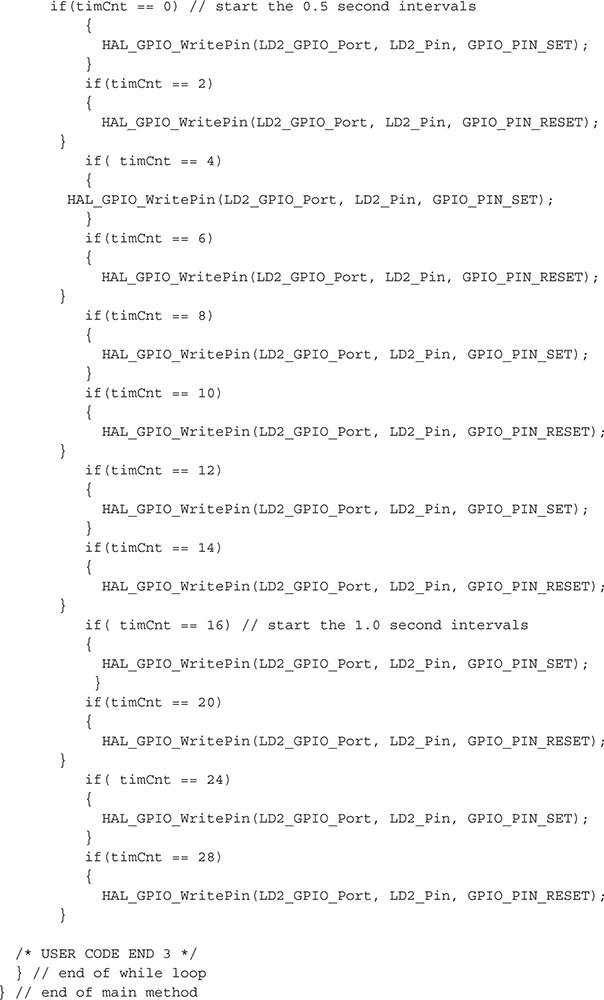
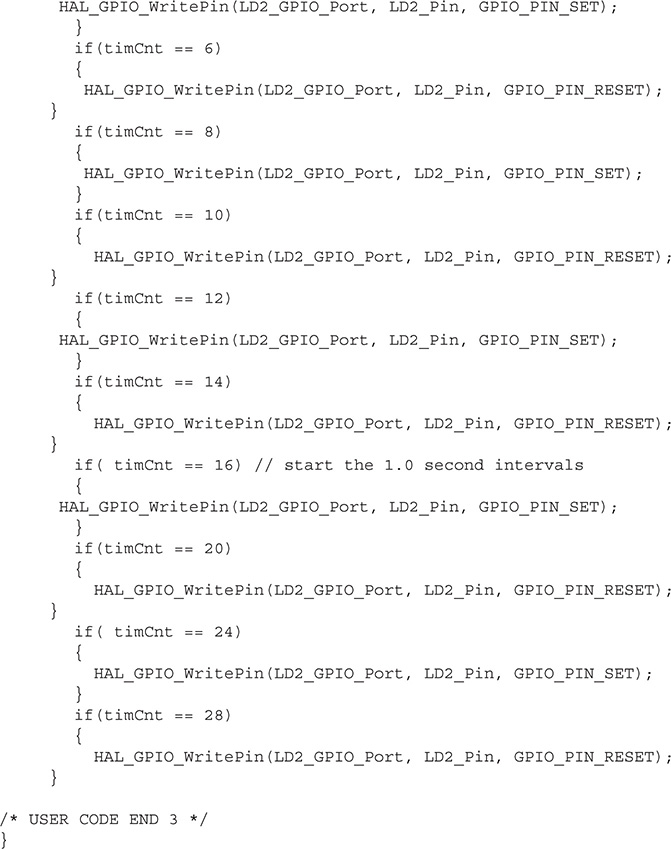
The forever loop contains a series of if statements that will be triggered based on specific counter values. The statements within the if statements either set or reset the user LED. Each counter increment takes 0.25 s to complete, which means that two increments will take 0.5 s. The LED will toggle at two times per second for the first 4 s. The second set of 4 s will toggle the LED once every second.
This code format is rather lengthy, but it does trade code space for simplicity. It is rather easy to follow the algorithm step-by-step to determine how the LED is controlled using this format.
Test Run
I built the project and then uploaded it into the Nucleo-64 board. The user LED immediately began to blink at a 0.5-s rate for 4 s and then at a 1.0-s rate for 4 s, which confirmed that the program worked as desired.
Modification to the Multi-rate Program
I changed code snippet in the above forever code to make that much more compact. That modification is listed below.
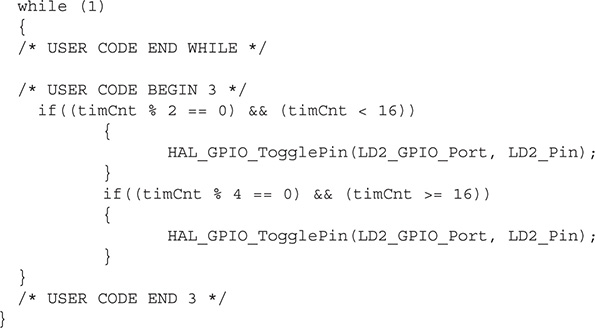
The program functioned just about the same with this modified code, which used the modulus operator along with a toggle method to control the LED. The code is much smaller than the original, but it is more complex and harder to understand and consequently maintain. This change highlights an interesting challenge that developers constantly face. This challenge is whether or not to use simpler code, which can take more code space versus using compact and “efficient” code, which is likely harder to understand and modify.
Test Run
I built the modified project and then uploaded it into the Nucleo-64 board. The user LED immediately began to blink at a 0.5-s rate for 4 s and then at a 1.0-s rate for 4 s, which confirmed the modified program worked the same as the original program. I did notice that the LED seemed to flicker more using this version vice the original. I can only attribute the flicker to the use of the toggle method versus the firm set and reset methods.
This last demonstration completes all discussions and demonstrations that I wished to convey regarding interrupts and timers. This chapter really is just the tip of the proverbial iceberg because there is a tremendous amount of information on these topics that I could not cover. There are almost 2,000 pages alone in STM’s HAL user manual. As always, the STM datasheets, and user and reference manuals will be an invaluable resource to learn about the many additional features and functions that you can carry out with interrupts and timers.
Summary
I started the chapter discussions with the focus on timers, which are important peripherals because they alleviate the MCU from having to directly perform timing functions. I explained the five available categories of STM timers, of which there are three types provided on the project MCU. These are basic, general purpose (GP), and advanced.
I next showed you how to configure a timer to perform a specific timing event. This discussion was followed by a demonstration in which the onboard LED blinked once per second. This demonstration did not use an interrupt, which was the focus of the second timer demonstration.
In the second timer demonstration, I showed how easy it was to integrate a timing operation with an interrupt process. In this demonstration also the onboard LED blinked, but it blinked using only the interrupt process.
The third timer demonstration showed how to restructure the interrupt process such that a multi-rate LED blink could be implemented. The interrupt callback method controlled a counter variable, which in turn controlled the actual LED activation within the forever loop.
In the final timer demonstration, I changed the original forever loop code with a much more compact and complex version with the same functionality . I did this to illustrate how developers must constantly decide on how to write code, simpler and consuming more code space or very compact and complex, which is harder to understand.