In order to design a controller, we first need to know what sort of game is going to be played. I am going to explain how to make a game where the player is given a letter and they have to press the button of that letter as quickly as possible. They are then told another letter. The player has to hit as many buttons correctly as they can in a 30-second time limit.
There are many ways in which this game can be varied; instead of ordering the player to press a particular button, the game could ask the player a multiple-choice question, and instead of letters, the buttons could be labeled with Yes, No, Maybe, or different colors. You could give the player multiple commands in a sequence and make sure that they press all the buttons in the right order. It would even be possible to make a huge controller and treat it as more of a board game. I will leave the game design up to you, but I recommend that you follow the instructions in this chapter until the end and then change things to your liking once you know how everything works.
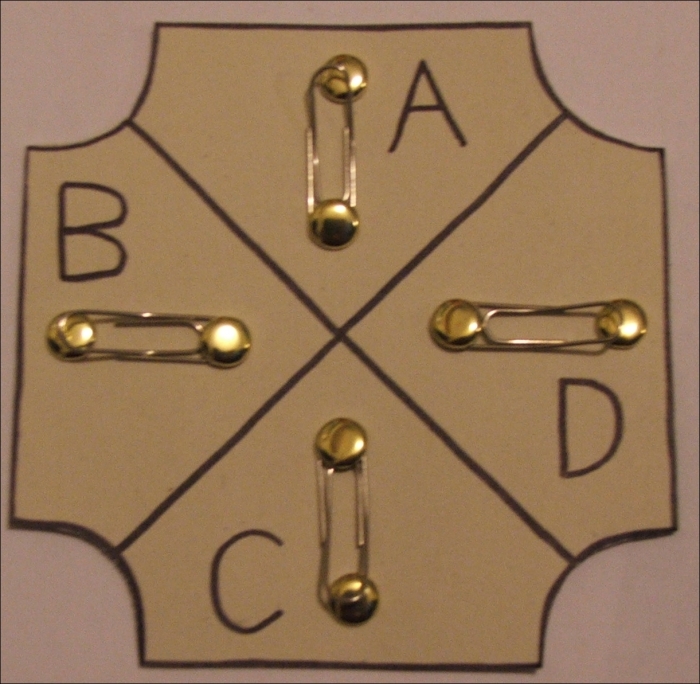
So, now that we know how the game is going to be played, it's time to design the controller. This is what my finished controller design looks like, with four different letters and its paper clip buttons in place:
Make sure each button area is at least a little bigger than a paper clip, as these are what the buttons will be made of. I recommend a maximum of eight buttons.
Draw your design on to the card, decorate it however you like, and then cut it out.
Now for each button, we need to perform the following steps:
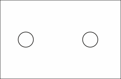
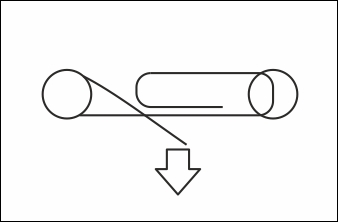
- Poke two small holes in the card, roughly 3 cm apart (or however long your paper clips are), as shown in the following figure. Use a sharp pencil or a pair of scissors to do this:
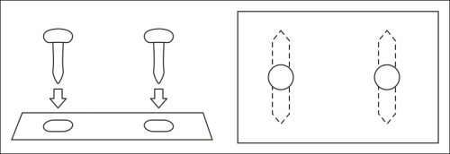
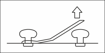
- Push a paper fastener through each hole and open them out:
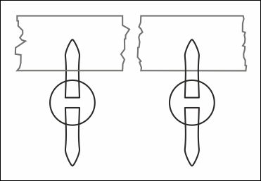
- Wrap a paper clip around the head of one of the fasteners, and (if necessary) bend it so that it grips the fastener tightly:
- Bend the other end of the paper clip up very slightly, so that it doesn't touch the second fastener unless you press down on it:
- Turn the card over and tape one leg of each fastener in place, making sure that they don't touch each other:
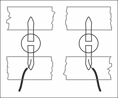
- Tape a length of wire to each of the two remaining legs of the fasteners. The ends of the wires should be exposed metal so that electricity can flow through the wire, paper fastener, and paper clip (as shown in the following figure). You might want to delay this step until later, when you have a better idea of how long the wire should be:
Now that the controller is ready, it's time to connect it to the Raspberry Pi. One of the things that makes the Raspberry Pi different from a normal computer is its set of General-Purpose Input/Output (GPIO) pins. These are the 40 pins (or 26 for older Raspberry Pi models) in the top-left corner of the Raspberry Pi, just above the logo. As the name suggests, they can be used for any purpose and are capable of both sending and receiving signals:
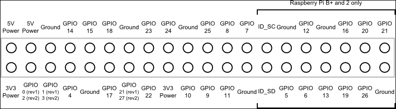
The preceding figure shows what each of the pins does (if you have 26 pins, these are the ones present on the left-hand side of the preceding image). In order to create a useful circuit, we need to connect one of the power pins to one of the ground pins with some sort of electrical component in between. The GPIO pins are particularly useful because we can make them behave like either power or ground pins and they can also detect what they're connected to.
Note that there are two versions of the pin numbering system. You will almost certainly have a revision 2 Raspberry Pi. The revision 2 boards have mounting holes, while the revision 1 board has none (these holes are surrounded by metal and are large enough to put a screw through them. It's easy to spot them if they're there). It is safest to simply not use any of the pins that have different numbers in different revisions.
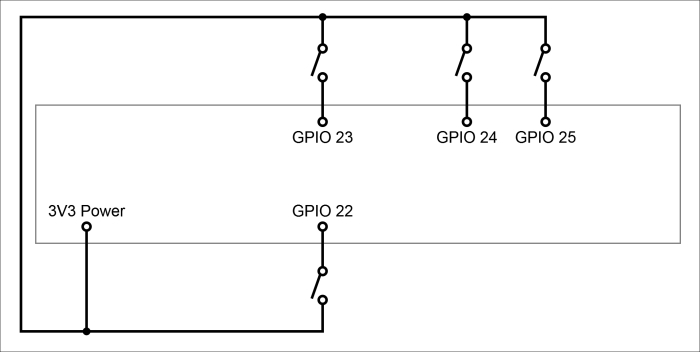
To connect your controller to the Raspberry Pi, connect one wire from each button to a 3.3V (3V3) power pin, and each of the remaining wires to a different GPIO pin (one with GPIO in its name, as shown in the previous figure). In my example, I will use pins 22, 23, 24, and 25. Everything is now connected, as shown here: