CHAPTER 4
Camera Controller
In this chapter, I will show you how to build a camera controller by using the RasPi with several auxiliary modules that will act as trigger sources. The controller will allow you to trigger a digital camera and/or an electronic flash if they are inherently capable of being remotely controlled. It will also enable you to take some very interesting pictures including stop-action photos.
The following three figures illustrate one simple experiment that demonstrates the controller’s stop-action effect. I made a flag object out of black and white duct tape onto which I printed the numbers 1 and 2. I attached this “flag” to a nail that I inserted into a portable drill chuck. Figure 1 shows the drill chuck with the flag at rest.

Figure 4–1 Flag at rest.
Next, I started the drill and had it rotating at approximately 500 revolutions per minute (r/min). Figure 4–2 is a normal photograph taken with my usual studio lights and without an electronic flash. This figure mimics what the human eye perceives in that both numbers are visible because I used a slow shutter speed.

Figure 4–2 Flag rotating at 500 r/min.
Figure 4–3 is a picture taken with the electronic flash and a slow shutter speed in a darkened room. You can clearly see the number 2 visible and not blurred, even though it was rotating at 500 r/min or almost 10 times per second.
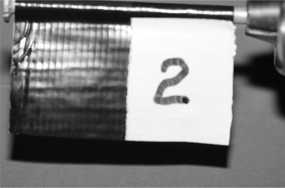
Figure 4–3 Flag captured in a stop-action photo.
The controller will assist you in making similar stop-action pictures as well as many other effects that you may want to accomplish.
Project Requirements
I will start this project by listing the requirements that the controller system should meet. These have been simplified to make the controller compatible with a wide variety of cameras and electronic flash units. In order to take full advantage of all the system functions, you will need a camera that is capable of being remotely triggered. The controller system requirements are shown in Table 4–1.
Table 4–1 Camera Controller Requirements

Figure 4–4 is a high-level graphical diagram showing the module interconnections associated with each mode listed in Table 4–1.
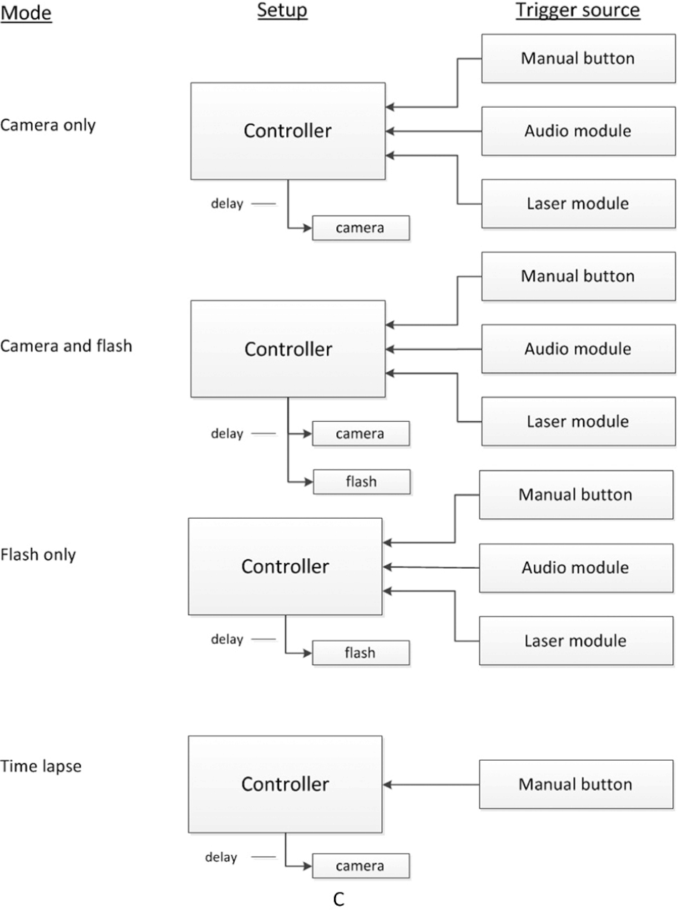
Figure 4–4 High-level camera controller diagram.
Camera Shutter Operation
A brief discussion on how a Digital Single Lens Reflex (DSLR) shutter operates will help you understand the interface between the RasPi and the camera. Modern DSLRs, such as the Canon 40D that I am using in this project, have a multifunction shutter control. The camera will autofocus when the shutter button is depressed halfway and operate the shutter with a full press. Figure 4–5 shows the interface connector that has both the focus and shutter-control pins along with the common or ground pin. There is 3.3 V present on both the focus and control pins, and connecting either pin to ground completes the circuit and causes its corresponding action (focus or control) to be actuated.

Figure 4–5 Canon 40D shutter-control connector.
A special plug has to be used with this connector. I cannibalized a commercial, inexpensive, remote shutter control in order to have a plug for this project. Figure 4–6 shows this plug with a molded cable.

Figure 4–6 Canon shutter-control plug and cable.
You can go to the website www.doc-diy.net/photo/remote_pinout/to look up your camera’s shutter-control pin layout and matching connector. Some of the newest DSLRs are using a standard 3.5-mm stereo jack that will make the interface connection much easier.
Do not despair if you do not have a camera capable of being remotely controlled. Simply use the sound or light-activated functions to trigger an electronic flash with your point-and-shoot camera set to a long exposure in a darkened room. The flash will illuminate the subject sufficiently to enable you to do stop-action photography. You will have to experiment with different exposure times to get the desired result, but you do have the basic equipment to be successful.
DSLR owners will learn how to activate the focus and shutter controls in the optoisolator section after reading the electronic flash discussions, which are next.
Electronic Flash
The electronic flash, or strobe, is the unit that produces a very bright light for a very brief instant in time. It is used to sufficiently illuminate a photographic subject where ambient light is too low in intensity or not suitable for the subject. The electronic flash replaced the one-time-use flash bulb many years ago and is now almost universally used in modern photography. Most digital cameras, from one-steps to DSLRs, have a built-in flash unit that automatically activates based upon the lighting conditions that the camera sensor detects. While this arrangement may suit most users, for this project, we cannot make use of the built-in unit but instead must rely on an external electronic flash that can be remotely triggered. Figure 4–7 shows the Canon 420EX electronic flash that I will use in this project. It is several years old and has been replaced by the model 430EX. For our purposes, however, the differences between the models are not significant.

Figure 4–7 Canon model 420EX electronic flash.
The 420EX is designed to mount into the camera’s hot-shoe connection that provides the shutter activation as well as a series of data interconnections. The data flow between the flash and the camera is not relevant to the project, as the flash will not be mounted on the hot shoe. However, it is important to point out the control connections that will be used to trigger the flash. These are detailed in Fig. 4–8.

Figure 4–8 Flash hot-shoe connections.
The flash will fire when the shutter-control pin is connected to the ground pin.
NOTE I used the descriptor, shutter control, to emphasize that the flash is fired only when the camera shutter operates. This pin obviously triggers the flash itself.
The ground pin, in actuality, consists of two spring-loaded, cam-shaped pins located on either side of the inner slides for the hot shoe. These make contact with the camera’s metal hot shoe. There are five spring-loaded pins shown on the bottom of the hot shoe. As mentioned earlier, we are only concerned with the center pin. The other four pins visible to the left of the center pin are data connections that are not used in this project. I also used an inexpensive, commercially available hot-shoe adapter to bring out both the shutter-control and the ground connections. This adapter is shown in Fig. 4–9.

Figure 4–9 Hot-shoe adapter.
The adapter brings out the connections to a 3.5-mm plug that can be inserted into a standard mono jack. The adapter also incorporates a standard tripod mount, as shown in the figure inset. This makes it simple to mount the flash in any position as needed.
Electronic Flash Control Voltages
You may have noticed that I put the 4.5-V control voltage in the Fig. 4–8 pin description. This is a typical voltage found on Canon electronic flash units, and it is quite compatible with this project’s interface circuits. However, older electronic flash units may have significantly higher voltages present on the control pin. These may range up to several hundred volts.
CAUTION Connecting an electronic flash with more than 24 V on the trigger contact to the project interface circuit will destroy the interface and may cause further damage to the RasPi.
Modern electronic flash units are expected to conform to ISO Standard 10330:2002 entitled “Photography—Synchronizers, ignition circuits and connectors for cameras and photoflash units—Electrical characteristics and test methods.” One portion of the standard requires that trigger voltages not exceed 24 V max. Canon has designed their units to operate at less than 6 V, and Nikon at less than 12 V. Older units were not designed to the standard and could conceivably have hundreds of volts exposed that would not only destroy the interface but also present a personal shock hazard. To check flash voltages for your electronic flash, go to the following excellent website: www.botzilla.com/photo/strobeVolts.html.
I do discuss a possible solution for using an older flash unit in the next section on the optoisolator interfaces. However, my earnest suggestion would be: Do not use an old flash, but instead invest in a modern unit. Many of these are available at quite reasonable prices.
Optoisolator Interfaces
An optoisolator combines a light source with a photosensitive transistor to create a photonic coupler. This type of isolator achieves electrical isolation between two electrical circuits that may have a significant voltage difference present. Figure 4–10 shows a physical schematic for the NTE3041 optoisolater that is used in this project. It is in a six-pin dual in-line package (DIP) form with a gallium-arsenide infrared LED as a light source and a silicon NPN phototransistor as the light receiver.

Figure 4–10 NTE3041 optoisolator.
Although it might appear that an optoisolator could pass analog or continuous signals, it is only suitable for digital or on/off signals. That is due to the on/off functional nature of the LED used as the light source. NTE3041s are used as input and output isolators in this project. Figure 4–11 shows a very simple circuit that is used to enable the NTE3041 to isolate one of the RasPi GPIO pins. All that is needed is a current-limiting resistor in series with the GPIO pin. The resistor value was set at 220Ω to provide a 10-mA drive current to the LED in the optoisolator. This current level is suitable for both the RasPi and the optoisolator. There is also a 3-V Zener diode connected in series with the photo transistor’s collector, which affords a bit of protection in case of excessive voltages that might be present in the output circuit.
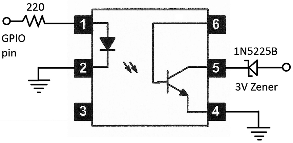
Figure 4–11 RasPi to optoisolator circuit.
CAUTION The NTE3041 is rated for a maximum of 30-V collector-to-emitter voltage (VCEO). Any voltage that exceeds that maximum rating will likely damage the optoisolator; however, the RasPi will still be protected.
I have used the NTE3041 optoisolators to connect the RasPi GPIO pins to the shutter (full press), focus (half press), and electronic-flash control pins. The sound and light modules do not require isolation, as they already use isolated relay contacts.
High-Voltage Optoisolator Circuit
Figure 4–12 shows a circuit that can be used if you need to control an electronic flash that has high voltage present on the control pins. This circuit uses an optotriac (triode for alternating current) isolator in lieu of the NTE3041 optoisolator. The optotriac, in turn, turns on a silicon-controlled rectifier (SCR) that fires the flash unit. The SCR recommended is rated up to 400 V. I strongly recommend you do not use a flash unit with more than that voltage.
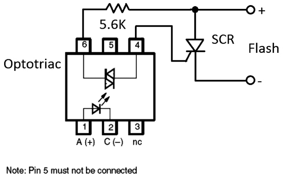
Figure 4–12 High-voltage optoisolator circuit.
Connect the RasPi GPIO pins to pins 1 and 2 of the optotriac in the same manner as shown in the NTE3041 connections of Figure 4–11. Be sure to include the 220 Ω current limiting resistor.
Information about the suggested parts for the high-voltage optoisolator circuit is provided in Table 4.2.
Table 4–2 High-Voltage Optotriac Parts List

Sound and Laser Modules
An important part of this project is to have the capability of triggering the camera and flash by using sound and light events. This means we need sensors to detect the sound and light as well as the associated circuitry to generate a signal when the preset thresholds are exceeded. These requirements raise an issue that often comes up in project planning: whether to build or buy. In this case, I decided to incorporate two inexpensive kits for sound and light detection. My decision was based on an estimate of how long it would take to build and test two prototypes versus buying and building two kits and making any appropriate modifications to suit this project. Listed here are the kits I used:
Global Specialties Model GSK-409
Audio Control Switch kit $9.95
Ramsey Electronics Model LTS1
Laser Trip Sensor kit $19.95
It turned out that neither kit required any interface modifications for use in the project, since both had output relays that could directly connect with the RasPi GPIO pins without the need for optoisolators.
Audio Module
An assembled audio module is shown in Fig. 4–13. You will notice that I connected the microphone to the main board with a foot-long twisted-wire pair, so that I would be able to position it for optimal sound pickup. The microphone is normally soldered directly to the main board, which would have made it awkward to position the board with the 9-V battery attached in order to best detect the trigger sound.

Figure 4–13 Model GSK-409 audio control switch.
This board does feature a flip-flop operation where the output relay is latched after a sound event. This means that relay contacts will close and remain closed after the first sound event. The next sound event will open the relay contacts, and they will stay that way until the next event, ad infinitum. This is really not a limiting feature for the project, since you would probably have planned to manually reset the module before any event using sound as a trigger.
Notice the sensitivity trim pot that I have pointed out in Fig. 4–13. I found that I had to adjust the pot almost fully clockwise, in order to have a reasonable opportunity to detect low-to-moderate volume sound events.
This module is easily connected to the Pi Cobbler prototype board using the schematic shown in Fig. 4–14.

Figure 4–14 Sound module to Pi Cobbler interface schematic.
Point 1 shown in Figs. 4–13 and 4-14 is connected to the Pi Cobbler ground pin. Point 2 also shown in Figs. 4–13 and 4-14 is connected to GPIO pin 24 on the Pi Cobbler. There is also a 10-kΩ pull up resistor tied to the GPIO pin. The RasPi control program will be written to detect the high-to-low transition on the selected GPIO pin.
Laser Module
An assembled laser-light module is shown in Fig. 4–15. There are two assemblies, not counting the 12-V power supply, that make up this sensor module. The first is the laser pointer that acts as the light source, and the second is the light sensor that consists of a phototransistor with some analog signal processing circuitry. The laser pointer is a very common low-power device that is typically battery powered. In this case, it is powered by 5 V supplied by the detector board. The power is delivered through a pair of small alligator clips, one of which is visible in the Fig. 4–15.
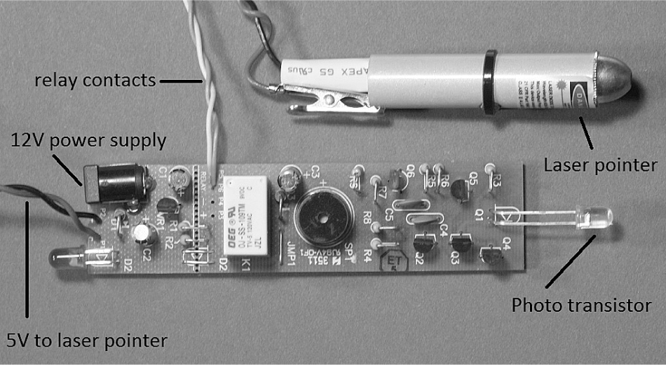
Figure 4–15 Model LTS1 laser trip sensor.
The light detector component is a phototransistor that is also pointed out in the figure. It looks like a normal LED but is a transistor with only the collector and emitter leads externally connected. It will conduct when the laser light strikes the base-emitter region; however, it seems insensitive to normal ambient light. I have not tried it in strong direct sunlight where I suspect it might conduct. I also purposely left off an ambient light shield to show you the transistor. When put in place, the light shield will help with false triggers.
The relay contacts in this module are normally closed when light is not being detected and will open when the laser light strikes the phototransistor. This means that the RasPi program will need to be changed to detect a low-to-high transition provided the same interface is used, as is shown in Fig. 4–14. That’s what is so nice about using the RasPi and Python: changes can easily be made in software to accommodate hardware issues.
Interface Connections
All of the interface connections are shown in Figure 4–16. There are three input push buttons to manually trigger focus, shutter, and flash; three output optoisolator connections that allow the RasPi to trigger focus, shutter, and flash; and finally, there are two inputs from the sound and light modules. This might seem to be a lot, but the circuits are quite simple and repetitive.

Figure 4–16 All of the interface connections.
The hardest part was to interconnect the modules, camera, and flash to the breadboards. I finally determined that using audio cables terminating with 3.5-mm jacks was the easiest way for me to do it. You can use whatever you have available, such as a twisted pair, because the connections are DC based with practically no speed or bandwidth issues. The complete prototype is shown in Fig. 4–17. It is a bit of a “rat’s nest” as far as the wiring goes, but it is totally functional and allowed me to rapidly progress with the project.

Figure 4–17 Complete camera controller prototype.
CAUTION Ensure that you use the appropriate ground connections, as shown in Fig. 4–16. For instance, the camera ground is separate and distinct from the RasPi ground. No harm would result if you inadvertently connected the optoisolator grounds to the breadboard ground, but the isolators would simply not function properly.
Table 4–3 lists all the GPIO pins used in the interface with the associated functions tied to those pins.
Table 4–3 GPIO Pin Function Interface List

NOTE Starting with revision 2 for Models A and B, pin 21 has been redesignated pin 27. It remains pin 21 for revision 1 models A and B. The Pi Cobbler, Pi Plate, and likely other prototype tools have pin 21 shown. I would suggest putting a piece of tape over the 21 and relabeling it 27 if you are using revision 2 models. The GPIO library recognizes pin 27 without any issues.
Testing the Interface Connections
You should test all the connections to ensure that everything is wired correctly. The only item you will need is a standard volt-ohm meter (VOM) to run through all the tests. You will not require any software to be running on the RasPi for these tests although the RasPi must be turned on in order to provide power to the Pi Cobbler and breadboards.
First check each of the push buttons. There should be 3.3 V present on pins 18, 22, and 23. The voltage should drop to 0 V when one of the buttons connected to the pin under test is pushed.
Next, check the camera optoisolators. First ensure that the wires going from pins 4, 17, and 21 are temporarily disconnected. Then plug the shutter-control cable into the camera and then turn on the camera. Using a jumper wire, connect the 3.3-V power supply on the breadboard to the 220-Ω resistor that connects to pin 1 of the optoisolator.
CAUTION Do not touch pin 1 on the optoisolator with the 3.3-V jumper wire. You must go through the current-limiting resistor or else the LED in the optoisolator could burn out from excessive current.
You should observe either the camera auto-focusing or the shutter operating, depending upon which optoisolator you are testing.
The electronic flash should be tested next. Plug the remote hot shoe into the flash and ensure that it is also connected to its controlling optoisolator. Turn on the flash and then touch the 3.3-V jumper wire to the 220-Ω, current-limiting resistor that is connected to the optoisolator. The flash should operate.
Remember to reconnect all the wires between the optoisolators and their respective GPIO pins, as shown in Fig. 4–16.
The sound and light modules are tested last. Connect the modules to the breadboard and power them on. You do not have to disconnect the wires going between the GPIO pins and the module interfaces for these tests. The sound module connection will be either on or off, depending upon the state of the latched relay. Using the VOM, check to see that pin 24 switches between 3.3 V (on) and 0 V (off). This is a valid test for the sound module because it operates in the same manner as the push-button interface.
The laser-light module is checked in a similar fashion at pin 25. However, as mentioned above, the module-relay contacts are closed when light is not striking the phototransistor. This means that pin 25 should have 0 V when no light is on the sensor and 3.3 V when light strikes the sensor.
If you have any problems, recheck all the wiring, since it is very easy to misplace a jumper wire on the solderless breadboards. Also, ensure that you have all the appropriate grounds connected, as shown in the figures.
Initial Test Program
The following program tests the camera focus and shutter controls as well as the electronic flash by using the push buttons. It is named CameraControl .py and may be downloaded from the book’s website, www.mhprofessional.com/raspi.
I recommend running this program directly from a terminal window as follows:

Press each of the push buttons and confirm that the appropriate action occurs. When you are finished, type ^c to exit the program.
You should note that I reset the controlling GPIO pin after making it a HIGH value. This ensures that it is in the proper state for the next operation.
Sound Module Test Program
The following program tests the sound module to check that the focus, shutter, and flash can be triggered when the sound module detects a sound event. The first portion of this program is identical to the previous program. This program interacts with you through the screen by prompting a number representing the test to be performed. The prompts are shown on the screen and are also shown here:
1—Test the shutter only.
2—Test the flash only.
3—Test the shutter and flash together.
0—Exit the program.
The program is coded as a series of loops that wait for a trigger event from the sound module before activating the requested function(s). This program is available on the book’s website as SoundModTest.py.
Just be aware that you must reset the sound module after it has been triggered because of the latched operation. It is a simple matter of a one-hand clap to trigger it so that the module LED turns off and the module is in a proper ready state.
Light Module Test Program
The program to test the light module is almost identical to the sound-module test program.. The only changes are in the three GPIO.input conditional if statements that need to be changed from if(GPIO.input(24) == False) to if(GPIO.input(25) == True). These changes are required because the light module is connected to pin 25 in lieu of pin 24 and its relay contacts are normally closed instead of normally open, as I mentioned earlier in this chapter.
To save book space, I will not repeat the code listing, as the changes are minor. This program, SoundModTest.py, is available from the book’s website and is named LightModTest.py.
To test this module you will need to aim the laser at the phototransistor, which should turn off the LED on the detector board. Next, block the laser light beam with an opaque item, which should trigger the light module and initiate the requested function. There is no need to reset the light module, since it is not latched.
Time-Lapse Function
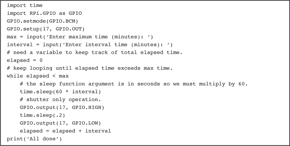
The last camera controller function to test is time-lapse photography. This is where you set a maximum time to take photos at a preset interval. I created the program using only the shutter function, as I believe that will be its primary use. Normally, time-lapse photography is done outdoors without the need of a flash. Also, it doesn’t make sense to incorporate the sound or light triggers for this function. The program is quite simplified as compared to the previous programs and is listed below. It is also available from the book’s website as TimeLapse.py.
NOTE The interval should be entered as a decimal if you need fractions of a minute, i.e., an interval of six seconds would be entered as .1.
Operational Code
The four test programs, CameraControl.py, SoundModTest.py, LightModTest.py and TimeLapse.py should serve as templates to create whatever style operational program meets your needs. It is impossible for me to create the wide variety of control programs that are possible because there are so many different environments that would need to be accommodated. It is easy to add additional functionality to any of these programs by simply adding the desired input and/or output triggers. For instance, if you needed a flash for the time-lapse function, you would add GPIO.output(27, GPIO.HIGH) after the GPIO.output(17, GPIO.HIGH) statement and do a similar add after the GPIO reset. Also note that I used 27 in lieu of 21 due to the rev 2 board I used.
TimeLapse.py
Summary
This chapter started with a project-requirements list that also served as a list of goals that you needed to accomplish. Requirements drive all projects, and you should spend a great deal of time analyzing and determining what the essential requirements or needs are before proceeding to any design work.
I next discussed how a DSLR camera with an electronic flash could be remotely controlled. I elected to use optoisolators where appropriate to lessen any chance of damaging voltages being introduced into the RasPi interface circuits. I also mentioned that you could use a non-DSLR camera, set to a long exposure, with the electronic-flash function to capture stop-action events.
In a detailed discussion regarding optoisolators, I explained that they are very handy for completing interface circuits that incorporate a high level of voltage isolation. I also provided a triggering circuit for those brave souls with a high voltage electronic flash.
I went through my build-versus-buy decision regarding the sound and light modules. I was very pleased to find that I had made the right decision, as I had no trouble incorporating these kits into the project. You will find that your time is very valuable and finding ways to shorten a project, such as incorporating prebuilt components and/or kits, can be a valuable tool for maximizing your productivity.
I next went through a step-by-step testing procedure to ensure that the interface circuits were working as designed. There was no need to run any programs on the RasPi at this stage. It is always a prudent idea to carefully check and test all interface circuits before running any programs. Testing in this fashion allows you to determine that any later functional problems are probably due to program glitches, not the interface circuits.
I then introduced a series of four test programs to methodically check that all planned project requirements were met and that all the components functioned as desired. These four programs will serve as good templates to allow you to create your own custom programs. You can design them to best suit your needs, or you can simply use them as they are.


