CHAPTER 11
Local and Remote Logic Controller
Introduction
This project consists of two major parts both of which concern logic control, or put simply, turning IO pins on and off. The two project parts are closely related, and both involve the control of IO pins: one uses an external board that provides eight additional GPIO pins, and the other is based on the RasPi itself.
The external board uses the 1-Wire protocol that was introduced in the Chap. 10 project for building a weather station. This board may be either controlled through a program running on the RasPi or accessed using the home network, as was demonstrated in the Chap. 10 weather project.
The other project part directly controls the RasPi GPIO pins. This part may be thought of as an extension of the fundamental concepts that were first discussed in the Chap. 2 demonstration of a blinking LED. In this part, the GPIO pins will be controlled from an Android smartphone client application, with the RasPi acting as a web server. The RasPi may also be controlled from a browser, which will also be demonstrated.
At the end of the chapter, I will discuss how both project parts can be accessed over the Internet .
The good news regarding this project is that there is very little hardware construction involved. The more interesting (never bad) news is that a fair amount of software installation and configuration is involved; however, at this stage in the book, you should be fairly comfortable dealing with such activities. Now we’ll look at the 1-Wire external control board.
1-Wire External Control Board
The 1-Wire board I’m using is the Hobby Boards 8 Channel I/O v2.0 board, as shown in Fig. 11–1. It is part of the series “29” family and is fully compliant with the 1-Wire protocol.
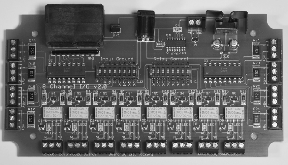
Figure 11–1 Hobby Boards 8 Channel I/O v2.0 board.
Significant board specifications are listed in Table 11–1.
Table 11–1 8 Channel I/O Board Specifications

An eight-position DIP switch labeled “Relay Control” is on the board. It can disable any of the relays if you wish to do so. Another eight-position DIP switch labeled “Input Ground” is used in connection with the input terminals. Inputs should be connected as follows:
1. Non-powered inputs—Connect one lead to the positive terminal marked “+.” The other lead is connected to the powered screw terminal marked “+5v.” The corresponding “Input Ground” DIP switch should be in the on (up) position, which is also the default position.
2. Powered inputs—Connect one lead to the positive terminal marked “+.” The other lead is connected to the negative terminal marked “–.” The corresponding “Input Ground” DIP switch should be in the off (down) position. The input polarity is a “don’t care” situation because the input opto-isolators are bidirectional, as can be seen in Fig. 11–2, which shows a portion of the board’s schematic. You can even use low-voltage AC to trigger the input.

Figure 11–2 8 Channel I/O board input schematic.
The full schematic along with the board’s user’s manual is available from www.hobby-boards.com.
Each channel relay is connected in parallel with the 1-Wire controller and the respective input for that channel. This means that the relay can be activated by a network command or by an input action, such as a contact closure. I will demonstrate this dual action in a later section of this chapter.
A block diagram of the 1-Wire network used in this project is shown in Fig. 11–3. The USB to 1-Wire adapter and 1-Wire Sniffer Module used in the Chap. 10 project are also being used in this project. The 8 Channel I/O board is also configured to supply power to the entire 1-Wire network.
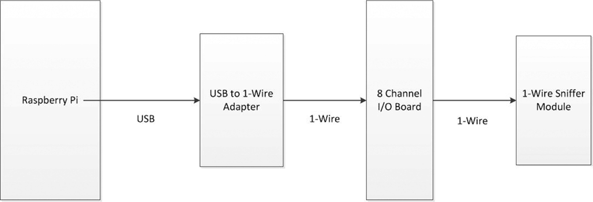
Figure 11–3 Block diagram of the 1-Wire network.
All the modules are interconnected using Ethernet patch cables except for the special RJ12/RJ45 cable that connects the USB/1-Wire adapter and the I/O board.
1-Wire File System (owfs) Installation and Configuration
The software required to control the 8 Channel I/O board needs to be built from the owfs source code in a procedure similar to that followed in Chap. 9 for the libnfc software. This time, I will not include the many screenshots shown in Chap. 9, since you should now be somewhat familiar with the build process. I do caution you to carefully follow all the steps because it is quite easy to miss something, and consequently, to be unsuccessful in creating the operational software. The prerequisite conditions for the build are to have an Internet-connected RasPi running the latest Wheezy distribution with a powered USB hub attached. You can also choose to login remotely by using an SSH connection, but that is not a requirement.
1. The first step is to simply plug the USB/1-Wire adapter into the powered hub and confirm that the Wheezy OS recognizes the adapter. You should also attach the remaining modules at this time. Then type the following at the command line prompt:

Figure 11–4 shows what displayed on my setup. The USB/1-Wire adapter is shown as “Bus 001 Device 005: ID 04fa:2490 Dallas Semiconductor DS1490F 2-in-1 Fob, 1-Wire adapter” entry. Your entry will vary depending on the adapter you use and the unique ID that is associated with every 1-Wire device.

Figure 11–4 lsusb display.
2. This step is a precautionary one to ensure that the Wheezy distribution is updated and upgraded. Type in the following commands:

(This can take some time if there are many upgrades needed.)
3. Next, the required build tools need to be installed. Type in the following command:

4. The source code has to be downloaded next. Type in the following command:

5. Extract the source code and subdirectory from the archive file by typing:

6. Change from the “pi” directory to the newly created “owfs-2.8p15” directory by typing:

7. The source code must now be “configured.” Type:

(This step takes about three minutes to complete.)
8. The build happens next. Type:

(Be patient; this takes over 30 minutes to complete.)
9. Finish the build process by typing:

(It takes about one minute.)
10. You now need to create a directory where the device files may be accessed. Type:

11. I found the next step useful as a way to ensure that the RasPi was in a good or consistent state. Type:

Login as you would normally, and you should be in the “pi” directory.
12. You now need to start the owfs filesystem and identify the mount point. Type the following:

NOTE This command should be done only once after the initial boot. If you try to remount the 1wire directory from the command line prompt after an initial mount operation, it typically results in a “Permission Denied” error. However, I did find that remounts were possible if used in a program statement. So-called “nonempty” warnings were created by the owfs file system.
Figure 11–5 is a screenshot showing the results of the mount operation. I then changed directories from “pi” to “1wire” by typing:
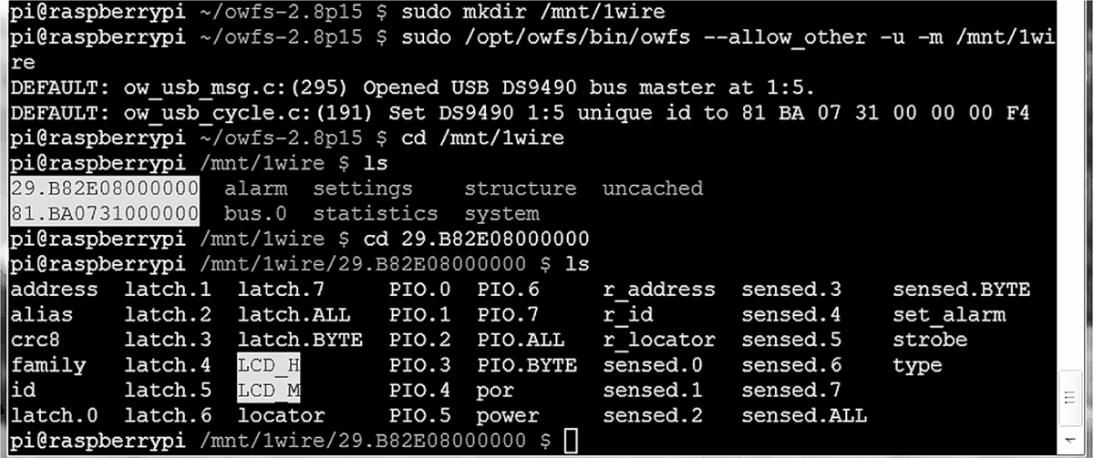
Figure 11–5 1-Wire owfs mount operation.

I did an “ls” to display the 1wire directory contents that identified the two normal 1-Wire devices on the network (the Sniffer Module is non-conforming). The USB/1-Wire adapter belongs to the family of 1-Wire devices beginning with the string “81.” That meant the remaining directory, starting with the family designator of “29” must be the 8 Channel I/O board.
I changed into that directory by typing:

The directory contents are displayed at the bottom of Fig. 11–4.
I would like next to clarify an important aspect of how Linux treats hardware before proceeding much further into this part of the project.
Linux, Hardware, and FUSE
Unix and its descendent Linux “treat everything as files” according to the old mantra. This phrase encompasses all things, including hard drive files, serial ports, thumb drives, etc. You can read and write to a hardware device, if it accommodates such actions, in exactly the same way as you can read and write to an ordinary file, provided the permissions are properly set. The view that everything can be handled as a file certainly simplifies how programs handle data to and from hardware devices.
There is also another particular file category that doesn’t appear until the OS is running. In this category are virtual files that are dynamically created upon demand and are often-times stored in the /sys directory. The Filesystem in Userspace (FUSE) application supports the owfs application by creating and storing these virtual files in FUSE registered directories. The “/mnt/1wire directory” is the designated site in which to store all the virtual files created for the 1-Wire network currently operating.
You can prove to yourself that the virtual files exist. Simply reboot and do a “ls” on the /mnt/1wire directory. Nothing will show. Next type in the mount command from step 12 and redo the “ls” command. Then you should see a directory data display like the one shown in Fig. 11–4 for the 1wire directory. owfs applications and FUSE are integral to each other; the system wouldn’t work without either of them.
Another very useful feature is that the 1wire directory will automatically be updated as modules are removed from and/or added to the 1-Wire network. Figure 11–6 shows what happened before and after I plugged a Temperature Module (family “28”) into the 1-Wire network. Note, that I did not have to type any commands; the addition was automatically detected.

Figure 11–6 Autodetection of 1-Wire Modules.
You will see that a new directory entry named “simultaneous” appeared in the listing. This new entry was created by owfs and FUSE after the programs recognized that the new module was part of the Temperature Module virtual file properties. This dynamic recognition and autoconfiguration is a very powerful concept, which contributes to making 1-Wire networks so easy to install and use.
Test Sequences for the 8 Channel I/O Board
What follows are some quick and simple terminal commands to test the basic board functions. Figure 11–7 shows the test setup, using a laptop that is controlling the RasPi with an SSH session, i.e., “running the Pi headless.”

Figure 11–7 1-Wire test setup.
If you haven’t yet done it, mount the 1wire directory, using the command from step 12 shown above. Remember: attempting to remount after doing it once will result in a Permission Denied error. To clear the error, all you have to do is reboot the RasPi and reissue the mount command.
Next, you need to change directories to be in the 8 Channel IO board directory. For my system the command entered was:

Your command will be slightly different because the board’s unique serial number and family name make up the directory name. Simply “cd” into /mnt/1wire and then “ls” if you haven’t previously recorded the board’s directory name.
Testing the Outputs
Once you are safely in the device directory, do another “ls” to see all the different files owfs and FUSE have created. Then type the following:

You should be rewarded by hearing all eight relays click and seeing all eight LEDs light up. This command simply sends a byte of all “1’s” into the file named PIO.BYTE that controls all eight relays simultaneously. Tired of seeing all the LEDs lit? Type the following:

All the LEDs should be off now and all the relays deactivated.
Of course, specific relays may be activated by sending the appropriate bit pattern encoded into the equivalent decimal number to the PIO.BYTE file. For instance, if you wanted to turn on relays 1, 3, 5, and 7, you would need to send 85 to PIO.BYTE. The number 85 was calculated by using the binary weights listed in Table 11–2.
Table 11–2 Relay Binary Weights

To turn on relays 1, 3, 5, and 7, all that is needed is to sum the binary weights associated with each relay:

Type the command:

Relays 1, 3, 5, and 7 should now be activated and their LEDs on. You now know how to turn them off.
Individual relays may also be controlled by using specific files dedicated to each relay. For example, to turn on relay 4, type the following:

Relay 4 turns on. The individual relay file names start at 0 not 1. This is not true for the board relays, which are numbered 1 through 8. This difference is a small detail that can nonetheless cause some confusion.
Testing the Inputs
Sensing inputs is very similar to setting outputs except for one major difference. A ‘1’ is used to indicate that no input is present or detected. All the relays must also be disabled, by turning all the switches on the Relay Control DIP switch to the off (down) position. This configuration is required because an IO line cannot be both an input and an output at the same time.
Next, ensure that nothing is connected to any input and then type the following:

You should see the value 255 displayed just before the command line prompt, just like the circled number in Fig. 11–8.

Figure 11–8 Result for the sensed.BYTE command.
The value 255 is the decimal equivalent of all 1’s for 8 bits or 1 byte. To test this concept out a bit further, connect a jumper wire between the screw terminals marked “+5v” and “+” on input terminal 8. What would you expect to see displayed after you type in “cat sensed.BYTE”? A moment’s thought might help you realize that the binary value of the bit for the number 8 input (relay binary weight of 128) would be 0; hence the value should be 255–128 or 127. Go ahead and type the command:

You should be rewarded to see the value 127, just as you expected. It’s not really too hard after all!
Now it is time to try out a Python program to exercise the 8-Channel I/O board. You first need to enable all the relays by putting all the Relay Control DIP switches to the on (up) position.
Python Test Program
This program cycles relays 2 and 4 every 10 seconds forever unless stopped by a keyboard interrupt that is done by pressing the ‘control’ and ‘c’ keys simultaneously (^C). I also included a statement to autoload the 1wire directory so that the command shown in step 12 does not have to be explicitly entered. The file object statement will have to be modified to suit your installation, since it has the unique address for my 8-Channel I/O Board hard coded into it. This file is named ow_eight. py and is available from the book’s companion website, www.mhprofessional.com/raspi.
Type the following at the command line prompt:

Relays 2 and 4 should click, and the associated LEDs should blink on for 5 seconds then off for 5 seconds. This program should be used as a starting point from which you can develop your own control program to match your desired application.
Remember that a given I/O channel may be used either as an input or an output but not as both simultaneously. This is precisely the situation with the RasPi GPIO pins where a particular pin may be set as an output for one part of an application and then used as an input in another part. The major difference between the RasPi and the I/O board is that a physical switch must be set on the I/O board, while a GPIO pin may be reset by a program statement with the RasPi. It is just a bit more limiting to use the I/O board as compared to the pure programming situation allowed with the RasPi. However, having eight channels available provides a good deal of flexibility.
Caution The relay contacts are rated for a maximum of 250 mA at 250 V AC, which equates to an approximate 60-watt load. Do not attempt to switch more than a 60-watt load using these light duty relays, and under NO circumstances should you try to control a line voltage AC motor. If you want to control a heavy AC-inductive load, use the relay to control a motor controller that is rated for the AC load. This is a safe practice, and one that should be adhered to at all times.
ow_eight.py

Sniffer Monitoring
I was interested in monitoring the 1-Wire network activity while the ow_eight.py program was running. Figure 11–9 is a screenshot from my laptop running the Tera Term program that I discussed in Chap. 10. The laptop was connected to the Sniffer Module, using a USB-to-serial adapter and cable.
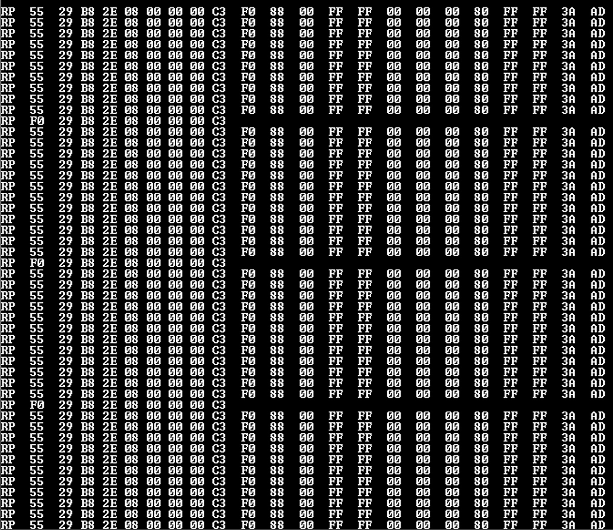
Figure 11–9 Sniffer packet activity.
The figure shows the repeated activity of switching the selected channels on and off, which was expected. What was not expected is the periodic polling of the 1-Wire network taking place every two minutes. That may be deduced by observing the shorter packets interspersed among the repeated control packets initiated by the ow_eight program. The two-minute interval was calculated by knowing that each repeat packet was issued every 10 seconds.
While not critical for program development, the sniffer is a very handy tool that helps you understand what is occurring within the 1-Wire network.
Android Remote Control
In this section I will show you how to control the RasPi GPIO pins by using an application running on an Android smartphone. The smartphone application is named DrGPIO and is available as donationware from the Google’s Play Store app. Donationware, as the name implies, means that you may donate to the author if you use it and find it useful. You must also download the web server portion named WebIOPi. Follow this procedure to download and install the server:
1. Type the following at a command line prompt:

2. Next, extract the source code:

3. Change directories to the newly created one:

4. Install and set up the software using a preset script:

NOTE I had the initial setup fail on me. I did the following to resolve the issue:

Repeat step 4 above.
Figure 11–10 shows the end result of the setup command.

Figure 11–10 Setup command end result.
5. The HTTP web server is started using Python as follows:

The 8000 is optional because it is the default. I like to include it, since it is a reminder of the actual port number. Figure 11–11 shows the console display for the web server starting.

Figure 11–11 Starting the WebIOPi HTTP web server.
The user name is “webiopi” and password is “raspberry” if you are asked for them by the application. The service may be stopped by either a keyboard interrupt (^C) or closing the terminal window in which it was started. You may also start and stop the web server as a service using these commands:

The web server can even be started during the boot process by entering the following command:

Testing the Web server with the Android App
I set up the RasPi with a Pi Cobbler prototype tool to drive three LEDs, as shown in the Fig. 11–12 diagram.

Figure 11–12 Test setup diagram.
You will need to determine the RasPi’s local IP address in order to connect the Android application to the RasPi web server. In my case, it was 192.168.1.21. All I needed to do was type that address into the phone, as shown in Fig. 11–13.
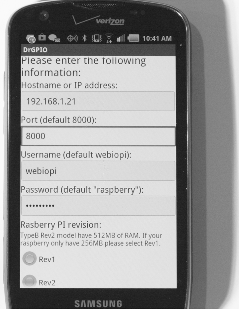
Figure 11–13 Android smartphone setup screen.
Scroll down to the bottom of the phone screen after you have entered the needed information. Tap on the button “Save and continue” and a pop-up dialog box will appear stating “DRGPIO is going to try to connect to your Raspberry Pi now.” Tap the OK button, and you should now be shown a screen similar to the one in Fig. 11–14.
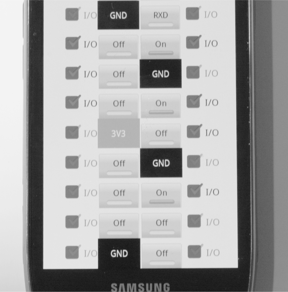
Figure 11–14 The DrGPIO control screen.
Figure 11–14 is a graphical representation of the RasPi 26-pin GPIO connector. The check boxes shown immediately to the side of each pin box allow you to select whether the pin is to act as an input or output. The check mark will be highlighted if it is set as an input. We need pins 18, 23, and 25 unchecked so that they are functioning as outputs. To output a 1, simply tap the pin box. The bar in the pin box will fill in, and the label will change from “off” to “on”. The pin will now be outputting a 1, or high level (3.3 V DC). Figure 11–15 is a picture of the test setup with the three LEDs turned on.

Figure 11–15 Functioning output test setup.
Testing the inputs is very easy. Just select the pins that you want to be used for inputs by ensuring that the check marks are highlighted and then connect those pins to the 3.3 V DC power supply. Figure 11–16 shows the phone screen with pin 18 set as an input and also connected to the 3.3 V DC supply. Pins 23 and 24 were left as outputs.

Figure 11–16 A phone input test screen.
Sharp-eyed readers may have spotted two additional pins that are set up as inputs and appear as if they are “on,” yet are not connected to the 3.3 V DC. These two pins are called floating inputs, meaning they are unconnected and can receive stray voltage that can trigger a false reading of a high input. I deliberately left this condition in the figure to show you that you can unwittingly create a short circuit to ground by resetting a floating input GPIO pin to output without removing the ground wire.
Testing the Web Server with a Browser
The HTTP web server may also be run from any local computer’s browser. Simply type in the RasPi’s local IP address with port 8000 as a suffix. In my case this was:

Figure 11–17 is a display of the resulting web page. All the configurable GPIO pins were set as outputs for this screenshot. All the functionality discussed in the Android section is available using a browser. Using a browser in this manner makes configuring GPIO pins very easy without the need to create any Python code to test basic I/O for a hardware project. I highly recommend that you consider using this approach to speed up your project development.

Figure 11–17 WebIOPi web page using a browser.
Internet Access
You will need your router’s public IP address to be able to remotely control the RasPi’s GPIO pins. Determining this address has already been discussed several times in previous chapters. You will also need to enable port forwarding on the router so that any browser or smartphone using port 8000 will automatically be forwarded to the RasPi’s local IP address. I had no problem in setting this up on the Android smartphone and on a remote computer’s browser.
The only issue is to remember which GPIO pins are connected to which devices. It would definitely be a problem if you wanted to turn on your home’s front outdoor light but accidently started the lawn irrigation system. The WebIOPi GUI may be customized to use different widgets and labels to suit your particular application. It does require a knowledge of HTML and Javascript to accomplish this, which is well beyond this book’s scope. I refer you to the WebIOPi documentation located at https://code.google.com/p/webiopi/. There is a lot of information at this site, including a discussion of Representational State Transfer (REST), which is the underlying technology that powers the web server. It is well worth your time to look at the content and gain an appreciation of what is happening “behind the curtains”.
Remote Access to the 8 Channel I/O Board
The first step is to ensure that the owfs HTTP server is running. Type this at the command-line prompt:

Next, open a browser on a computer that is part of the local network and go to the RasPi’s local IP address with port 2121 appended. In my case, this was:

Figure 11–18 is a screenshot of the opening web page. This should look somewhat familiar, as I described a similar operation in Chap. 10, when opening a web page to access the weather station data.

Figure 11–18 Initial web page for 8 Channel I/O board.
I then clicked on the 8-Channel I/O Board directory named 29.B82E08000000, which revealed the web page shown in Fig. 11–19. I apologize for the fine print here, as the figure has been resized to make it fit on a page in this book. It is definitely readable in a browser window.
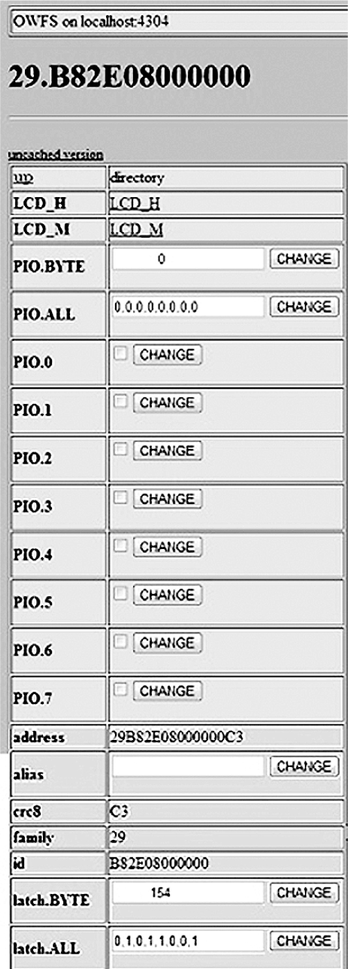

Figure 11–19 Directory 29.B82E08000000 web page.
One neat feature is that now you can enter relay control numbers directly into the box labeled PIO. BYTE and click on the Change button. I entered 255, clicked on the Change button, and instantly heard eight relays click and saw all eight LEDs light up. You should also review Fig. 11–5 to understand why this web page is so big. All the files listed in the device directory are also displayed on this web page. All the data operations discussed in the section entitled “Testing the Inputs” are available through this web page. Figure 11–20 shows the result of entering 255 in the PIO.BYTE box.

Figure 11–20 Testing the PIO.BYTE data entry.
I did notice that starting the owfs web server stopped the owfs file system application and unmounted the files in the 1wire directory. I do not believe this should be a real problem because you will likely be using either one or the other but not both simultaneously.
Internet access will be done in exactly the same way as discussed above except the forwarding port is 2121.
Summary
The 1-Wire 8 Channel I/O board was first examined with a detailed review of the board’s key specifications. This board provides an expanded number of GPIO pins beyond the RasPi’s seven.
Next, a 12-step build and configuration process that created an owfs development environment supporting the I/O board was carefully explained.
I then took a brief digression to explore Linux, FUSE and owfs. This explanation should help you understand how owfs functions.
Testing the I/O board inputs and outputs came next. I used only commands entered at the terminal prompt to exercise the board functions.
A short Python program, ow_eight.py, that controlled the I/O board through a series of output commands was demonstrated. A brief view of the Sniffer Module output was also shown. The ow_eight.py program should serve as an example of how to create more complex programs suited to unique applications.
I next showed you how to control the RasPi’s GPIO pins by using an Android smartphone application named DrGPIO along with the WebIOPi web server installed on the RasPi. I also demonstrated how you could operate the same functions with the same WebIOPi web server by using a regular browser.
The chapter concluded with a demonstration on how to control the I/O board using the HTTP owfs web server from a browser.
