
CHAPTER 15
Serving up Time with an RTC and NTP
Introduction
This project is focused on how the RasPi keeps track of time both locally and through a network. As designed, the RasPi contains no means to set or track time. This design decision was made both to keep the cost down and to minimize the printed circuit board (PCB) size. In addition, the capability would be available in the rev B model because it has a network port that is able to connect to a public Network Time Protocol (NTP) server. An automatic NTP connection is also built into the standard Wheezy Raspian Linux distribution designed for the RasPi.
The RasPi A models and B models without Internet access do not have public NTP service and, thus, require another means to set and track time. This is where a hardware peripheral known as a real-time clock (RTC) becomes very handy. First we’ll discuss the RTC and then take a comprehensive look at the NTP service.
Real-Time Clock (RTC)
The RTC module, which has been available for many years, first appeared with the advent of the PC in the early 1980s. There were timing systems available before that period, but they were fairly complex and expensive devices and suitable mainly for mainframe computers. The RTC introduced with the first PC was based upon an integrated chip named the MC146818, which was manufactured at that time by the Motorola Corporation. A modern version of that chip is used in this project. It is the DS1307, pictured in Fig. 15–1, which is manufactured by the Dallas Semiconductor company, previously mentioned in Chaps. 10 and 11.

Figure 15–1 DS1307 DIP.
The DS1307 is an I2C controlled device, as may be readily seen by the block diagram shown in Fig. 15–2. It is a fairly simple peripheral that uses a quartz-crystal-controlled oscillator in conjunction with a binary counter that is labeled as an oscillator and divider in the diagram. The crystal is rated at a nominal 32,768 Hz frequency (equivalently 32.768 kHz), which is exactly the value of 2 raised to the fifteenth power. Therefore, a 15-bit binary counter will overflow or reset once every second if a 32.768 kHz signal is input to the first stage of the counter. Theoretically, this setup will produce a once per second clock tick. Notice, I used the word theoretically, as the reality is that the clock crystals typically used with the DS1307 do not produce a perfect 32.768 kHz waveform. Figure 15–3 shows the actual crystal used in this project.
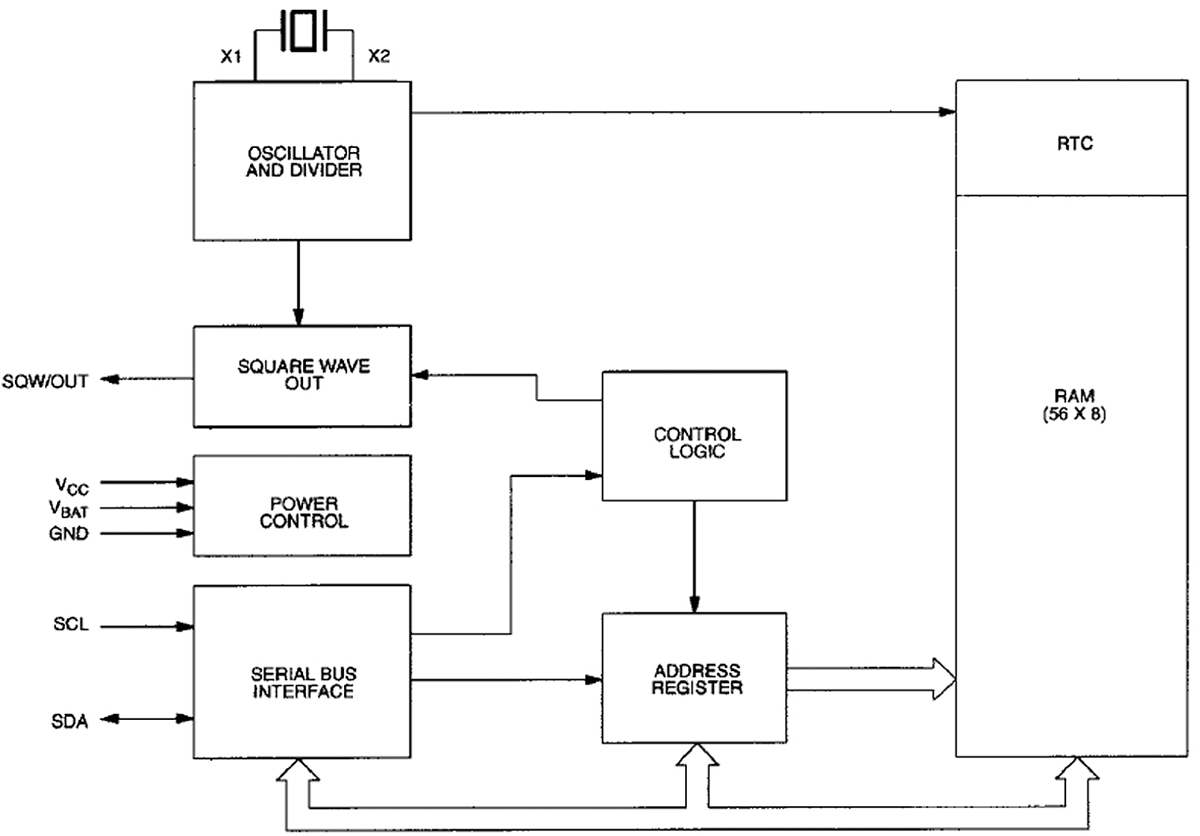
Figure 15–2 DS1307 block diagram.

Figure 15–3 RTC crystal.
You should clearly see the frequency in kHz printed on the metal can enclosing the actual piezo-electric element. These generic type RTC crystals typically will have accuracy within ± 30 seconds/month when properly loaded with a matching 6 picofarad (pF) crystal and operated at a nominal 23°C ambient temperature. The operating temperature is the key parameter that affects clock accuracy, assuming the correct capacitance loading is used. Figure 15–4 shows the temperature effect as it deviates from the standard 23°C calibration point.

Figure 15–4 Temperature versus RTC frequency deviation.
The ± 30 seconds/month accuracy will be maintained for a RasPi operating in a home or office. However, a RasPi that operates in severe environments should expect significant reduction in RTC accuracy.
Another key feature of the RTC is the ability to maintain the time even if the host processor is turned off. This is made possible by using a long-life battery to power the oscillator and non-volatile (NV) RAM (write mode) in the DS1307 chip. A lithium coin cell battery is normally used for this purpose after the host is powered off. A coin cell will often last for many years before exhausting its energy. The current date and time is continually stored in the NV RAM 56-byte memory.
Figure 15–5 shows the RTC breakout board used in this project. It is built from kit number 264 purchased from Adafruit Industries. It uses the DS1307 chip along with the crystal shown in Fig. 15–3. There are two resistors not installed, but are shown as placeholders on the PCB. This is because the RasPi already has two pull-up resistors attached to the Serial Data Line (SDA) and Serial Clock (SCL) control lines, negating the need for these components.

Figure 15–5 RTC breakout board.
The building kit is very easy to put together because there are only five components to install including the coin-cell holder. Each one has a placeholder noted on the PCB. Just be very careful when soldering the crystal to the board because you do not want to overheat it or excessively bend the fragile leads.
The RTC breakout board is connected to the RasPi by using a solderless breadboard with the Pi Cobbler prototype connector. The wiring connections are detailed in Table 15–1.
Table 15–1 RTC to RasPi Connections

The physical configuration is shown in Fig. 15–6 without the ribbon cable attached to show all the jumper wires.
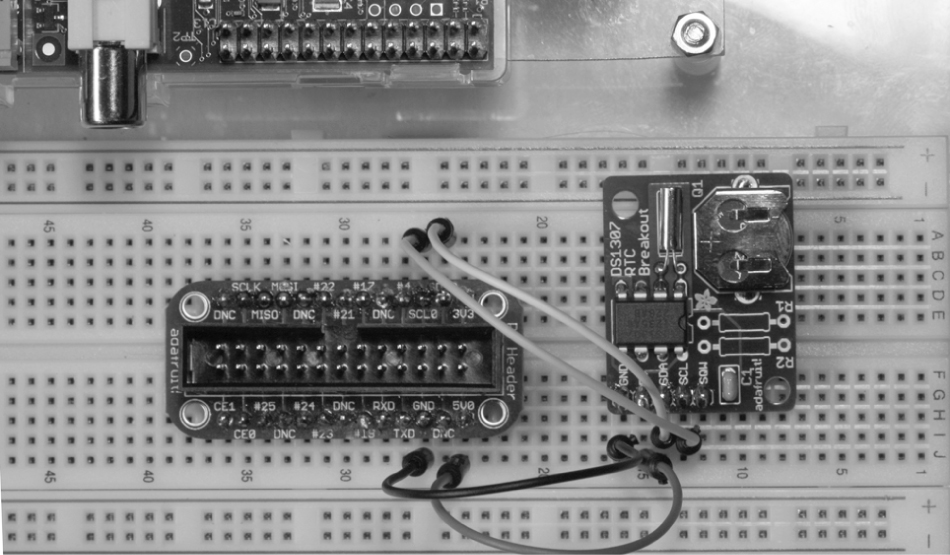
Figure 15–6 RasPi and RTC setup.
NOTE Even though the RTC is powered by the 5-V RasPi power supply, the I2C signal levels are still at an acceptable 3.3-V level.
RTC Software
The procedure discussed in this section is based upon a fine tutorial developed by LadyAda on the Adafruit website. The RTC chip uses the I2C protocol for communication with the RasPi, which means that the basic I2C software must be installed in the Wheezy Raspian distribution. The detailed I2C installation procedure shown in Chap. 12 should be accomplished before you proceed with the following software instructions.
Enter the following command in a terminal window to confirm that the RTC is detected by the I2C bus:

NOTE Note Replace the 1 with a 0 if a rev 1 RasPi is being used.
Figure 15–7 is a screenshot showing that the RTC board was detected at address 0 × 68.

Figure 15–7 Detecting the RTC board on the I2C bus.
The next step is to load the RTC module software, which is done by entering this command:

The modprobe application loads what is known as a loadable kernel module (LKM), which in this case, is named rtc-ds1307. You may have to run the following two commands if the LKM is not found:

The next step is to instantiate the RTC object, which you must do at the root level using the following commands:
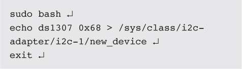
NOTE i2c-1 is for a rev 2 RasPi. Use i2c-0 for a rev 1 RasPi.
You may now check the time stored in the RTC by typing the following:

The RTC should report back, Jan 1 2000, if it has not been previously set. Figure 15–8 is a screenshot showing all the previous commands as well as the time. Notice that it reported a date different from Jan 1 2000 because I had rebooted the RasPi in the setup.

Figure 15–8 Screenshot of the RTC setup.
You will now need to set the current date and time for the RTC. This may be done in two ways. The first and probably easiest is to connect the RasPi to an Internet accessible network in order to set the current date and time. Simply plug in an Ethernet cable or a Wi-Fi adapter, and let the RasPi seek out and set its clock using the NTP service. After a minute or two, the RasPi should have acquired and set its system time to the current date and time.
The second method of setting the date and time is simply to enter it at a terminal prompt using the following sample as guidance:

The RTC will automatically reset its internal memory based upon your manual input.
You should always check on the system time after setting it by entering:

You may also force the RTC clock to synchronize to the system date and time by entering the following:

Next check the time reported back by the RTC by typing in the following:

Figure 15–9 is a screenshot showing the set time command as well as the time reported back by the RTC.
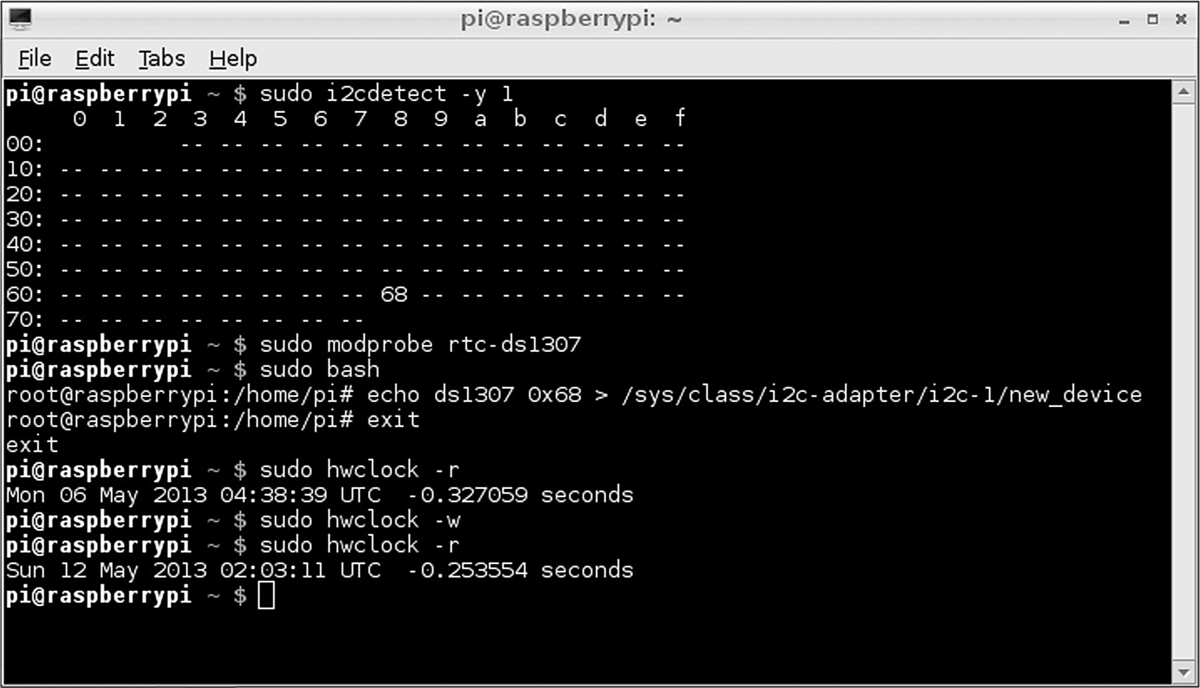
Figure 15–9 Screenshot of setting and checking the RTC date and time.
The next portion of this procedure concerns how to permanently configure the RasPi to use the RTC board. The rtc-ds1307 module must first be added to the LKM list that is stored in the /etc/modules file. To do this, edit the modules file by adding a line, “rtc-ds1307,” at the end of the list. Figure 15–10 shows this edit using the nano editor.

Figure 15–10 LKM module screenshot.
The last remaining step is to edit a file named rc.local that is located in the/etc directory. This file contains scripts that are run at the end of the boot process, which is how the RTC object will be created once the following script lines are entered into the rc.local file:

NOTE i2c-1 is for a rev 2 RasPi. Use i2c-0 for a rev 1 RasPi.
Figure 15–11 shows this edit using the nano editor.

Figure 15–11 The edited rc.local file screenshot.
I shut down the RasPi after completing the previous configuration steps and waited until the next day to restart the system in order to check the RTC function. Figure 15–12 shows that the date function worked perfectly, indicating that the RTC was performing as expected and accurately tracking the passage of time.
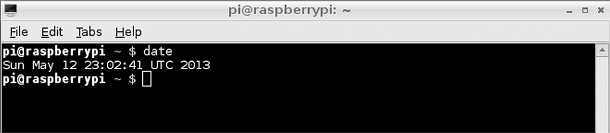
Figure 15–12 Screenshot of the date function.
Introduction to the Network Time Protocol (NTP)
NTP is probably the most common way time is set and maintained in today’s modern networks, including the Internet. The protocol itself was created by Dr. David Mills at the University of Delaware in 1985. Currently, Dr. Mills is an emeritus professor at the University of Delaware, where he was a full professor from 1986 to 2008. He, along with a team of volunteers, is still involved with the development and maintenance of NTP.
In reality, the NTP is implemented by a layered hierarchical network of computers, each one of which is set up as a time server running the NTP protocol. Figure 15–13 is a representative block diagram of this hierarchy.

Figure 15–13 NTP server hierarchy.
The layers in the NTP hierarchy are referred to as strata, starting with 0 and progressing to as high as 256. In reality, layers 16 or higher are considered unsynchronized and are probably not implemented. The highest layer, shown in the figure, is stratum 0, which consists of clock sources from which the actual time is referenced. There are a variety of primary clock sources available in the public NTP network, including sophisticated atomic clocks, GPS clocks, and the National Institute of Standards and Technology (NIST) time signal radio station WWVB to name a few. Stratum 1 connects directly to the clock sources and usually is a high-quality clock server source, but this is not always the case. NTP does not inherently guarantee that a server situated in the lowest-numbered stratum will provide the highest quality or most reliable clock signal. The reason for this is that the servers are networked and are constantly crosschecking the clock signals from other servers, both in their same stratum as well as in the strata situated logically above them. Poor-quality clock signals will be rejected from adjoining servers, and only quality signals will be passed on to other servers. Thus, it is entirely possible to have a server on a lower-level stratum (with a higher stratum number) provide a higher-quality clock signal than a server on a stratum closer to the primary clock sources. Don’t worry if all this sounds a bit confusing; I provide it only as background to promote your awareness of the underlying NTP structure.
A series of public NTP servers connected to the Internet are known as pool servers. The URLs for these servers are stored in the ntp.conf file located in the /etc directory. Figure 15–14 is a screenshot of this file.

Figure 15–14 Screenshot of the ntp.conf file.
There are four NTP servers listed, starting with 0.debian.pool.ntp.org through 3.debian.pool.ntp.org. The RasPi will typically connect to one or more of these servers each time it is booted. I am unsure whether the lead number 0 to 3 represents a stratum level; however, it is irrelevant, as the NTP software will automatically select the best clock signal and use it.
The RasPi NTP software is run as a daemon and requires no manual intervention for normal operation. The software is formally named ntpd with the “d” indicating a daemon application.
Building a RasPi NTP Server
I will show you how to build an NTP server that can provide accurate clock signals without the need to connect to one of the pool servers described above. Sometimes it is necessary to provide an independent NTP network server that does not rely on an Internet connection and can serve as a central clock source for all networked computers. There are commercial NTP servers available, but they typically cost anywhere from $1500 to $2000. Using a RasPi with a GPS will drop the cost to less than $100 and will provide the desired functionality.
The GPS used in this stage of the project is the same model previously discussed in Chap. 5. I will not repeat all the background and setup information provided in that chapter and will simply assume that you will follow those instructions in establishing the GPS to RasPi UART communications link. Refer to Fig. 5–15 in Chapter 5 to see the essential wiring required to connect the GPS module and the RasPi. You should ensure that the gpsd package is installed on the RasPi, as you will need it to process the GPS clock data. I recommend that you also install the CuteCom terminal control program. Using that program will enable you to easily confirm that both the UART link and the GPS module are functioning properly. Again, simply follow the procedures detailed in Chap. 5 to set up the GPS module and the RasPi to use the UART communications device ttyAMA0.
The ntp.conf file located in the etc directory must be edited to force the ntpd application to use the GPS instead of one of the pool servers. I commented out all the pool servers and added the following two lines to that section of the file:

Figure 15–15 is a screenshot of the edited ntp. conf file.

Figure 15–15 Screenshot of the ntp.conf file.
NOTE The pool servers will be uncommented after the GPS time server functionality has been proven, since it is good practice to leave these servers available.
Next the following series of commands will set up and run the GPS module as a clock source for the RasPi. Ensure that no Wi-Fi adapter or Ethernet cable is attached because they could provide a clock source if you didn’t comment out the pool servers listed in the ntp.conf file. All the commands should be entered in the sequence shown:

The killall gpsd command stops the gpsd daemon so that a logical socket link may be established by the next command. The /dev/ttyAMA0 parameter in the second command specifies that the GPS data will be sourced from the UART. The last two parameters, –F /var/run/gpsd.sock, set up a control socket for device adds and removals with the full path description to the socket. The last command starts the ntp daemon, at which point it will attempt to retrieve the clock signal from the source specified in the ntp.conf file.
The GPS module will continue to blink its LED until a solid lock is obtained on four or more satellites. A reliable time is not available until the LED stops blinking, which could take several minutes depending on the antenna signal strength. I used an external antenna and was able to consistently obtain a good lock in about two minutes. You may now use the date command to check on the precision time that is obtained from the GPS system.
The ntp.conf file must now be edited if all is well at this stage in the process. The following line indicates that the RasPi should be available as a stratum 10 server to other networked computers if desired:

Additionally, uncomment and edit the following existing line in ntp.conf:

I changed this line to:

This line allows the NTP server to broadcast the time to all computers located on the same subnet as the server. Your subnet may be slightly different. Type these three commands to ensure that the NTP server is operating:

I recommend using a program named ntpdate to confirm that a client computer is connected to and using the NTP server. Install the ntpdate program by typing:

Type the following command on the client computer (another RasPi) that is intended to use the NTP clock signal to confirm it is being received:

The local IP address for my NTP server is 192.168.1.43. Figure 15–16 is a screenshot of the ntpdate program output, clearly showing that the NTP service is being provided by the RasPi NTP server.

Figure 15–16 The ntpdate program output.
Summary
The first part of the chapter covered how to set up a hardware clock to be used with the RasPi because it does not incorporate one and would lack a time capability if not connected to the Internet. The hardware clock was based on the DS1307 chip and used the I2C bus to communicate with the RasPi. The clock board also incorporated a lithium coin cell battery that maintained the time even if the RasPi was turned off.
Next, I presented a brief background about the origin and function of the Network Time Protocol (NTP) that the RasPi uses when connected to the Internet. The NTP is implemented on the RasPi by the ntpd daemon, which is configured by a file named ntp.conf located in the etc directory.
Finally, I presented a section on how to create your own NTP server based upon a GPS clock source. The GPS module, first shown in Chap. 5, was the source used. It communicated with the RasPi using the UART link. Several changes had to be made to the ntp.conf file to enable the NTP server function. I finished the section discussion by demonstrating how to install and use the ntpdate application to test and prove that a client computer on the local network was actually using the RasPi NTP server.