CHAPTER 8
Home Security Controller
Introduction
For this chapter’s project, you’ll learn how to connect a webcam to the RasPi so that a homeowner can view a selected home area when an intrusion signal is detected by the RasPi. A laser trip device serves as the intrusion sensor. When the RasPi detects an intrusion signal, the RasPi will send an e-mail notification to a preset e-mail address to notify the homeowner that the laser has tripped, thus indicating that a possible intruder is on the premises. The homeowner will then open a browser, go to a website where the webcam video is available, and examine the ongoing activity. The homeowner could then determine whether to call the police or simply to disregard the alarm, if it had been innocuously tripped.
Motion is the name of the software package installed on the RasPi. It is a very sophisticated suite of vision applications that provides the project’s webcam monitoring function. Many other features are also available and will be discussed in the software section.
Webcam Selection
The webcam used in this project is a fairly new Logitech C920, as shown in Fig. 8–1.

Figure 8–1 Logitech C920 webcam.
The webcam has a high definition camera capable of producing excellent videos; however, the software used with it in this project will limit its performance. With that in mind, note that many different webcams may be used. In addition, the video requirements are quite low, and the Linux Raspian distribution will automatically detect quite a few types of webcams, including many older ones. If you already own a webcam, my suggestion is to plug it into a USB port and then type the following into a command line:

Figure 8–2 is a screenshot of the command’s output. Device 008 is the webcam and the other Logitech device listed is a keyboard. If in doubt about which device is the right one, when multiple devices from the same manufacturer show up, simply unplug the device and rerun the command to see which one disappears.

Figure 8–2 lsusb output screenshot.
One key point I discovered in creating this project is that the webcam has to be directly plugged into one of the two RasPi USB ports. The webcam was not detected by the software when it was connected to a powered-hub USB connector. I am not sure why this happened but it may be related to an issue with the hub power supply.
Protected Security Zone
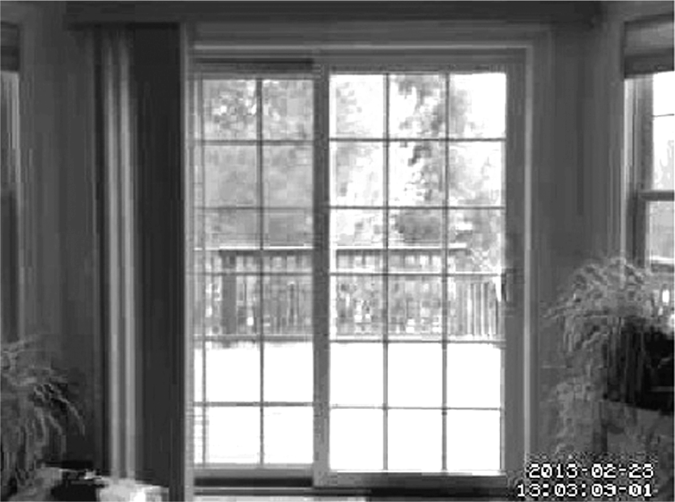
Figure 8–3 is an actual image capture from the webcam. It shows the protected zone, which, in this case, is the exit to my home’s back deck. I will discuss how images may be captured later in the software section. It is now important to show the intended protection zone because it greatly affects how the laser trip assembly will be deployed as part of the overall security scheme.

Figure 8–3 Protected Zone.
Laser Trip Assembly
I reused the same laser trip device that I used in the camera controller project. Figure 8–4 shows this assembly mounted on a single piece of Lexan. The only difference in this trip setup is that I used a mirror to reflect the beam back to the detector’s phototransistor when an object interrupts the beam between the laser pointer and the detector in the protected zone. The height at which you mount the laser and the detector board is your choice, but I found that about four inches above the floor worked quite nicely. The total path length of the laser beam was about 14 feet, which was not an issue with this system.

Figure 8–4 Laser trip assembly.
Figure 8–5 shows the laser trip assembly operating in the evening. This photo was taken with a flash to clearly show all the components, including the mirror to the right.

Figure 8–5 Operational laser trip assembly.
I took another photo, but this time in almost total darkness. In Fig. 8–6, you can see the emitted laser beam and a dot of reflected light in the mirror; however, you cannot see the projected laser beam. This, of course, conflicts with what you see in the movies when the hero (or bad guy) attempts to get past the laser beams protecting the secret vault or whatever. I would actually have to put smoke or dust in the beam’s path to see it, which would have caused much consternation in my household.

Figure 8–6 An elapsed-time photo of the laser trip assembly in operation.
The extra red light seen on the detector side is the returned beam reflecting off of the nearby white trim board. You could place some black cloth behind the detector if a more stealthy installation is desired.
The trip system functioned very well, never missing my exiting or returning. Another trip assembly could be stationed at four feet above the floor if you are worried about intruders simply stepping over the invisible beam. My philosophy regarding such matters is that criminals will simply go to easier targets if they suspect or detect that a relatively sophisticated intrusion system is in place and operational.
RasPi Interface to the Laser Trip Assembly
I have used the same relay switched circuit that was used in the camera control project. The schematic is shown in Fig. 8–7.

Figure 8–7 Schematic of relay switched interface for the laser trip assembly.
The circuit is extremely simple, yet highly reliable—two attributes that are important in security systems. The relay contacts are normally open, which means that the GPIO pin will be in a high state due to the 10 kΩ resistor tied to 3.3 V. The pin will go to ground or to 0 V when the detector is tripped. The software, thus, has to check periodically for a low state on the selected GPIO pin and then initiate all the desired actions, which will be discussed in the software section.
Motion Software Package
I selected a software package named Motion to enable remote viewing of the webcam. This is a comprehensive package that contains many features, far more than could be covered in this chapter. Being able to use this package from among the others available is why the RasPi is so useful. Creating similar software for a more traditional board, such as one from the Arduino series, would be a substantial undertaking, if it is even possible.
Motion also has the capability of detecting changes in the images from frame to frame, thus triggering an alarm based solely on real-time video analysis. I thought about using this feature but eventually decided upon the simpler approach of using an external trip system. Detecting an intrusion event based on the video alone requires the RasPi to be almost solely committed to vision processing, which could affect the availability of the video for remote viewing. This may have been an unwarranted decision, but remember that the Motion software was created years before the RasPi came on the scene and probably was based on using much higher-clock-speed PCs.
The key feature that is used from the Motion package is the built-in web server. This server receives the video stream from the webcam and sends it off in TCP/IP format over a predefined port. All you need to remotely view the webcam video is a browser pointed to the RasPi IP address and port number, nothing more. This feature makes the viewing exercise extremely simple. But there is more: Motion provides for using more than one webcam. You can set up multiple webcams, each with its own port number, so that it can monitor multiple locations throughout the home. Each webcam video feed is handled by what is known as a thread within the Motion software. I saw provisions for four threads in the Motion configuration file from which I presume four webcams could be handled. However, I seriously wonder if the RasPi has the processing power to manage four simultaneous video feeds. In any case, this project is only concerned with one feed that I know works very well.
Motion Features
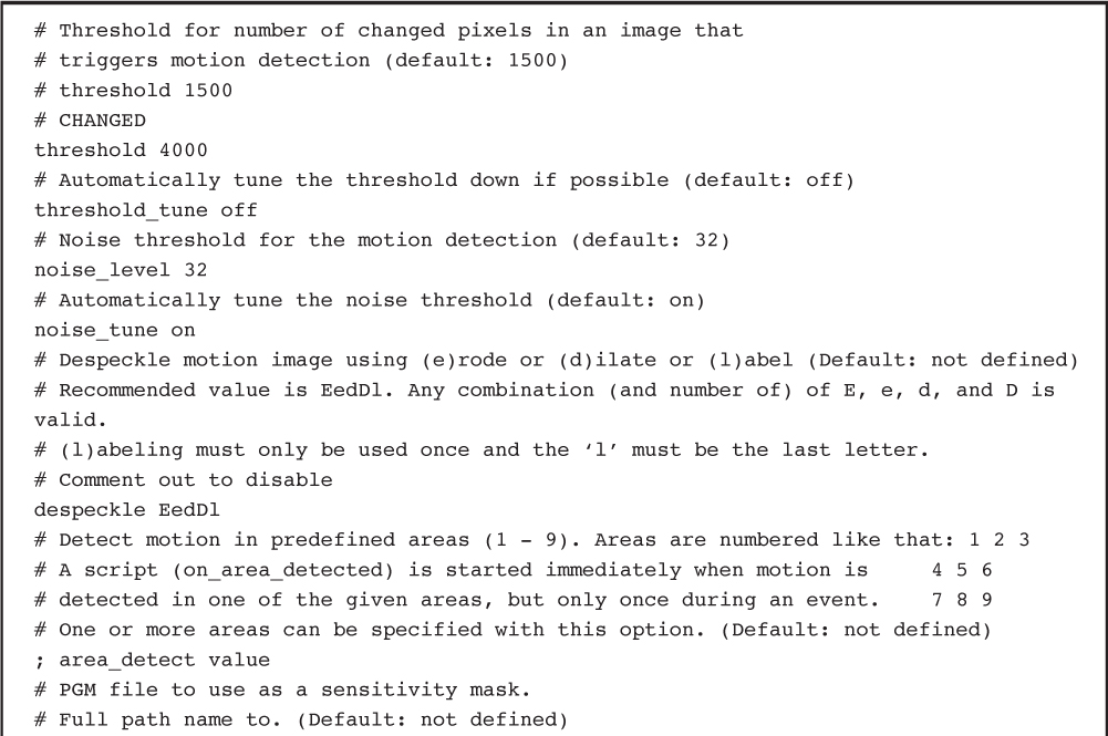
Motion has a substantial number of features that enable it to accomplish an amazing number of functions. The user manual is on-line at http://www.lavrsen.dk/foswiki/bin/view/Motion/WebHome, and it is over 100 pages in length. It would take a complete book to document all the features. However, the configuration file itself contains many self-documenting comments that should help you explore some of the additional features of this software package.
A portion of the configuration file dealing with motion detection is listed on page 107 to illustrate what I mean.
Motion Setup
You must, of course, install the Motion package before using it. I would strongly suggest that you update and upgrade your distribution before installing Motion. Simply type the following at a command line prompt to update and upgrade the Linux distribution in use:

Be patient, since the updates and upgrades can take a bit of time if there are many to install.
Next install Motion by typing:

Again, be a bit patient as this package is over 50 MB in size and has many component parts.
Motion will be run in the background as a daemon, which means that it will be a constantly available service. To enable the daemon, you must edit the /etc/default/motion file. Type the following:

You will see in the nano editor the line:

Change the “no” to “yes,” then save the nano buffer and exit the editor.
Next comes Motion’s configuration file. Motion has no GUI; it is totally configured by making changes to its configuration file, /etc/motion/motion.conf. This is a very big text file—well over 600 lines—although much of file’s contents are comments inserted to help the user. Fortunately only a few changes are necessary for this project. In Table 8–1, I provide the changes to be made to the configuration file section, but I do not give you step-by-step instructions because it should be fairly obvious by now how the editor functions.
Table 8–1 Motion Configuration File Changes

Again, start a nano editor session as follows:

Save the changes and exit the nano editor. Now, you must start the Motion server, which is done by typing:

One nice feature of having the Motion web server running as a daemon is that it is automatically started each time you boot the RasPi. You may also stop or restart the service by typing:

That’s it for the changes to make in the configuration file. I do want to briefly discuss why these changes were made. The change from daemon off to daemon on is obvious—it was needed to run Motion as a daemon. The next change—to make the port number 8081—is a bit historical, since the Motion web service has traditionally been assigned to this port. It is not a required port number and you can easily change it to any number that you desire as long as it is greater than 1024 and less than 65535. This range avoids the “well known ports” and goes to the maximum possible port number. My recommendation is to leave it at 8081.
The next change concerns localhost operation. Localhost refers to the same machine that is hosting the Motion web server. No other system can access the webcam if you restrict the service to localhost; hence it must be turned off.
The next two changes are similar to what was discussed above but are concerned with the remote control functions of the webcam. I do not enable any remote control functions, such as webcam panning or tilting in this project, but it is certainly doable. I suggest, however, that you simply keep the port number as assigned and disable the localhost operation.
Webcam Viewing
It is now time to test the remote webcam viewing functionality. You will need a separate computer on the same network that the RasPi is connected to. You will also need the RasPi IP address. It does not matter if the RasPi is connected via an Ethernet cable or by a Wi-Fi wireless adapter. My suggestion is to login into your network router and click on “Attached Devices.” The local IP address for the RasPi should appear in the appropriate list. My Netgear router has separate lists for wired and wireless devices connected to the network. Yours might be slightly different but should show something similar to Fig. 8–8.

Figure 8–8 Router attached devices list.
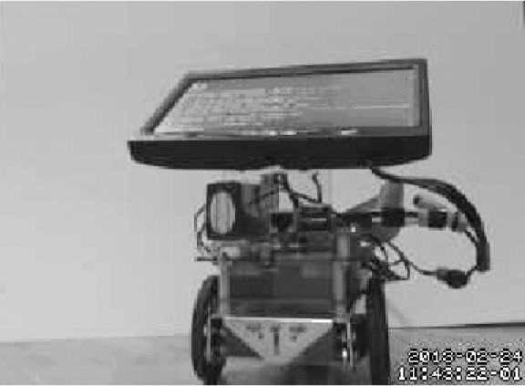
The entry RASPBERRYPI has the IP 192.168.1.21 on the wired portion of my home network. This is all I need to remotely view the webcam. I just have to type 192.168.1.21:8081 into a browser on another networked computer to view the real-time webcam video stream. Figure 8–9 is a screen capture of the video feed from the RasPi webcam. I used the robot car from Chaps. 12 and 13 as the subject.

Figure 8–9 Video stream screen capture.
E-Mail Notification
The next step in this project is to discuss the software that sends out an e-mail when the laser trip system is triggered. You will need a working Gmail account in order to have this software function because it uses a Python package named smtplib, which, in turn, uses Google’s freely available Gmail smtp server. The software is also designed to run in a home network using a router. I will show you how to obtain the public facing IP address that is dynamically assigned by your Internet Service Provider (ISP).
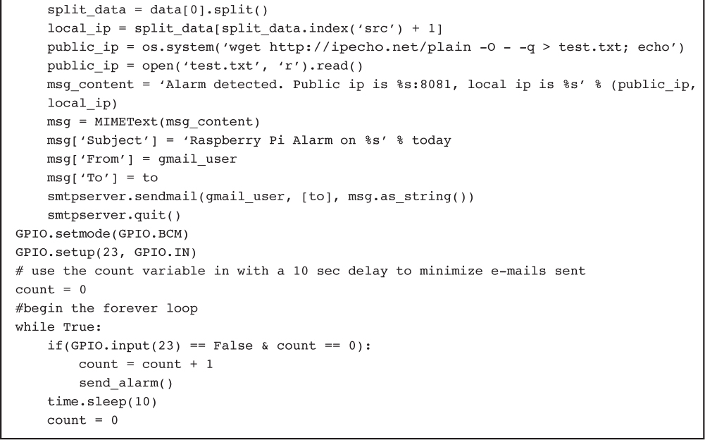
The Python code that sends out the e-mail notification is shown on page 110.
Figure 8–10 shows a slightly altered screenshot of the e-mail received after I ran this script (the names and public IP are changed to protect my privacy).

Figure 8–10 Sample e-mail notification.
I wish to mention two items regarding this program. First, the public IP is determined by using an external website, http://ipecho.net. There is no guarantee that this website will be operational for the indefinite future. If it becomes unavailable, then alternate sites should be used, and appropriate changes made to this program to accommodate the new site.
The second item is that I have not yet included the code for the GPIO trigger. This inclusion will consist of restructuring the program as a module that will be called when the laser trip activates the selected GPIO pin.
Laser Trip Program
The laser trip program sends the alarm e-mail when a low level on GPIO pin 23 is detected by the RasPi. The relay contacts shown as points 1 and 2 in Fig. 8–7 will close when the laser beam is interrupted. The contact closure puts a low voltage on pin 23, which is connected to the relay via the Pi Cobbler and a long cable, as shown in Fig. 8–11.

Figure 8–11 Laser trip assembly connected to the RasPi.
The complete program, named alarm.py, is available on www.mhprofessional.com/raspi and is listed on page 112.
Upon receiving the alarm e-mail, you would open a browser and type in the public IP address with the 8081 port, for example:

This should take you directly to Motion’s webcam server that is streaming the real-time video. What you do next is up to you, as I mentioned earlier.
I haven’t quite figured out what to do when an object, such as my cat or dog, decides to sleep in the path of the laser beam. I could set a maximum number of e-mails to be sent, which would be the sensible thing to do, or I could enable the RasPi to sound a loud buzzer, which might be the fun thing to do. I will leave that modification up to you.
Additional Sensors
I am sure you realize that additional sensors may be incorporated into this minimal security system. The software at present is designed to work with wired sensors, so it would be trivial to add additional door and window sensors. All you need to do is to wire them to selected GPIO pins and simply add the activation checks in the main “forever” loop. As mentioned before, up to four webcams can be managed by the Motion software. However, it is doubtful that the RasPi can handle four webcams. I would suggest that the send_alarm() module be modified to take an argument indicating which sensor has been activated. The send_alarm() module could use this argument to modify the e-mail to indicate which protected area has been tripped, for example, showing that a living room window has been opened. You could also incorporate the sound sensor from the camera control project to indicate suspicious sounds, such as glass breaking. There really are many ways to easily expand this security system with little expense.
You can even include wireless sensors for readers who have built the Z-Wave project in Chap. 7. You would need to explore the open Z-Wave software to see how a software trigger could be created based upon a state change on one of the network nodes. I showed a window sensor being activated in Chap. 7, but that state change was only shown in a GUI. I am certain that the underlying logical variable representing that state could be polled and the result sent to the alarm program.
Summary
I started this chapter by discussing the selection of the webcam to be used in the surveillance of the security zone. It turns out that Raspian Wheezy, the RasPi Linux distribution used, has drivers for different manufacturers including many older models.
The laser trip assembly used in the camera controller project was shown in its new role as the primary intrusion sensor. I reused the same interface circuit between the RasPi and the camera controller because it was simple and functional for this project.
The key software package, Motion, was discussed next. I used only a small portion of its capability, that being the webcam server. The Motion setup for the RasPi was discussed along with a demonstration of an actual webcam stream.
I introduced a notification program that will send an e-mail to a designated recipient that contains both the public and local IP addresses currently associated with the RasPi. This program was then incorporated into an overall program that sent the e-mail when the RasPi detected an intrusion signal.
Finally, I concluded with a brief discussion about future modifications and the ease with which additional sensors could be added to expand the system.


