CHAPTER 7
Home Automation
Introduction
In this chapter, I will cover how to effectively use the RasPi in a home automation system. But how do you define a home automation system? The answer is after you examine the needs and requirements of the homeowners, you design an automated system that best meets those needs. Hence, one size or type of automated system does not serve all; instead you start with a flexible base system that can be easily tailored to fit a specific situation.
The real purpose of a home automation system is to simplify a homeowner’s life. It accomplishes this goal by removing repetitive and tedious tasks and relegating them to a hardware and software system that never forgets, and accurately and consistently carries out the programmed tasks. Some of the tasks that a home automation system could handle are shown in Table 7–1.
Table 7–1 Home Automation Tasks

There are numerous base-system technologies available that have been developed over recent years to implement home automation. The most popular are listed in Table 7–2 with a brief description.
Table 7–2 Popular Home Automation Technologies
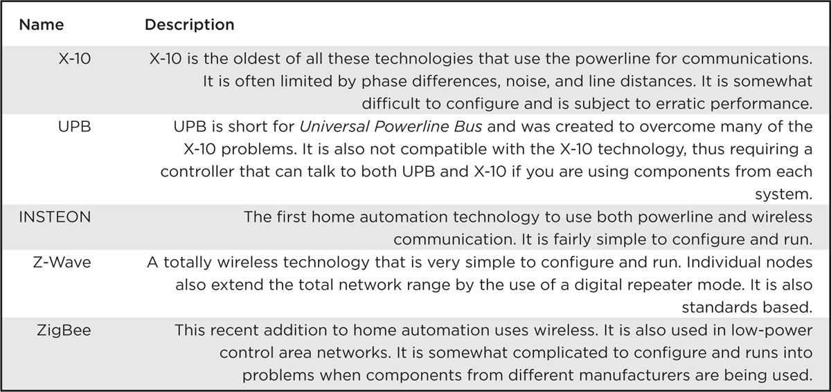
I selected the Z-Wave technology to use in this project because it is wireless, very robust, based on standards, and has components that are easily purchased and available from reliable manufacturers, including GE, Black & Decker, Schlage, ADT, and Draper. Anyone can purchase a Z-wave remote control and several nodes, and have an automation system functioning in a matter of minutes; the simplicity of setting up an automation system is what attracted me to this technology. This project replaces the remote with the RasPi and an attached Z-wave dongle. Of course, the RasPi is programmed to suit the homeowner’s needs.
There is no hardware construction involved in this project (the only physical task is to plug in a USB dongle), but that does not mean it is easy. A lot of software setup and configuration is involved in making the project run successfully. Of course, that’s part of the fun of working with the RasPi and Linux—many functions can be done in software versus building hardware peripherals.
Z-Wave Mesh Network
Each Z-Wave component or node contains a low-power radio-frequency (RF) transceiver. This radio operates in the Industrial, Scientific, and Medical (ISM) band at a frequency of 908.42 MHz in the United States and 860 MHz in Europe. These frequencies are far removed from other home wireless devices that typically operate at 2.4 GHz. It is thus far less susceptible to causing, or being subjected to, interference. The outdoor range, or line of sight, is approximately 100 m or 300 ft. The indoor range is about 30 m or 90 ft, due mainly to attenuation caused by the interior walls. Range extension is easily accomplished by simply adding additional nodes into the home.
Since each node is a transceiver, it both receives and transmits digital messages, acting as a digital repeater or “digipeater.” Digipeating creates a signal hop. There is, however, one major proviso: only four hops are allowed. After that, the communications protocol automatically terminates the signal in a process known as hop kill. This is done presumably to limit range and probably to remain in legal compliance with governmental regulations regarding low power, unlicensed operations.
Basics of Z-Wave Network Operation
The Z-Wave network, from its very beginning, was designed to be compliant with the ISO seven-layer network model. As such, its inherent design is based upon proven computer network concepts that are robust, efficient, and well understood by most system designers. Figure 7–1 shows the Z-Wave logical network stack with the corresponding ISO layer number. All subsequent network software developed for the Z-Wave network follows this model.

Figure 7–1 Z-Wave and ISO network layers.
Data sent through the Z-Wave network is in packets similar to the Ethernet format. Figure 7–2 shows how these packets are initially constituted at Layer 2 and subsequently modified at higher layers, as needed to suit the real-time network communication need.
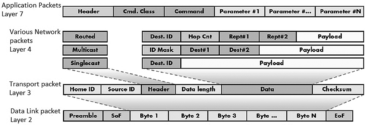
Figure 7–2 Z-Wave network packets versus model layers.
A basic packet is created at the Data Link Layer 2 that starts with a synchronization preamble followed by a Start of Frame (SoF) byte. Next comes the payload, which can be up to 64 data bytes and is terminated by an End of Frame (EoF) byte.
The Transport Layer 3 takes the basic packet and adds additional bytes, depending upon what is required in the communication process. Z-Wave is a connection-type network, similar to Ethernet, which has a very robust way of ensuring that packets get where they need to go. Layer 3 uses Acknowledgement (ACK) and Negative Acknowledgement (NACK) packets to maintain solid connections. A receiver node will send back an ACK packet to the sender if it successfully receives a data packet; otherwise, it sends back a NACK. This will continue until the original data packet is successfully sent or a preset number of retries is exceeded. Each node also uses Collision Detection Multiple Access (CDMA) to determine when to transmit on the network signal lines. It is akin to the old-fashioned telephone party line, where a user first listens to determine if anyone is talking and then starts talking if the line is free. In the case where a collision does occur, each potential sender “backs off” a random amount of time (tens of milliseconds) and then tries again. Using ACKs and NACKs depends upon an error-checking capability, which is why two checksum bytes are included in every data packet. These bytes are used by the receiving node in a mathematical algorithm to determine if the received data packet was corrupted during transmission. There are many good tutorials available on the Internet regarding checksums and error detection, if you are interested in digging further into the subject.
Layer 3 with the help of network Layer 4 further refines the packets by identifying what the packet type is, where it is going, and where it’s been, and then sets the data payload. There are five packet types used in the Z-Wave network, which are described in Table 7–3.
Table 7–3 Z-Wave Packet Types

Layer 4 sets up the routing, thereby ensuring that the packets are sent along the correct paths to reach the desired nodes. It also ensures that all nodes are repeating as configured. The routing configuration is maintained in a table stored in the primary network controller. It is possible to have multiple controllers on the network, but only one is designated as primary.
A simple network topology and descriptive routing table is shown in Fig. 7–3. A “1” in the routing table indicates a node-to-node logical connection.

Figure 7–3 Network topology and routing table.
Every Z-Wave network has a four-byte ID called the Home ID. Each primary controller has this Home ID that slave nodes acquire when they are joined to the network. Every secondary controller also uses this same ID when they are attached to the network. Individual slave nodes have a one-byte ID that is assigned by the primary controller when that node joins the network.
Network Devices
There are two main device types that make up a Z-Wave network: controllers and slaves. Slaves are also known as end-point devices because they can only respond to messages sent by the controllers. They typically have built-in microprocessors with GPIO pins that control components, such as TRIACs, which turn AC power on and off. Figure 7–4 shows a Z-Wave enabled duplex outlet. It would be installed in the same way as any ordinary duplex outlet would be installed, except that this outlet is also controllable using Z-Wave technology. The other big difference is that this outlet is much more expensive than a regular duplex outlet; however, you don’t need many of them for most home automation setups.

Figure 7–4 Z-Wave enabled duplex outlet.
Notice the white button to the left center of the outlet in Fig. 7–4. This is what a user presses to join the device to the network, when prompted by the controller menu. This operation will be shown in a later section.
Controllers have two subtypes: portable and static. Portable controllers are in the form of remote controls, one of which is shown in Fig. 7–5. These controllers must be able to self-discover their location within the network topology because they would not be typically placed in a fixed location. Such self-discovery is made possible by having the portable controller “ping” nearby nodes that are within RF range. The controller can, thus, join the network based upon the ping results. Portable controllers are battery-powered for portability reasons and are usually used as primary controllers in Z-Wave networks.
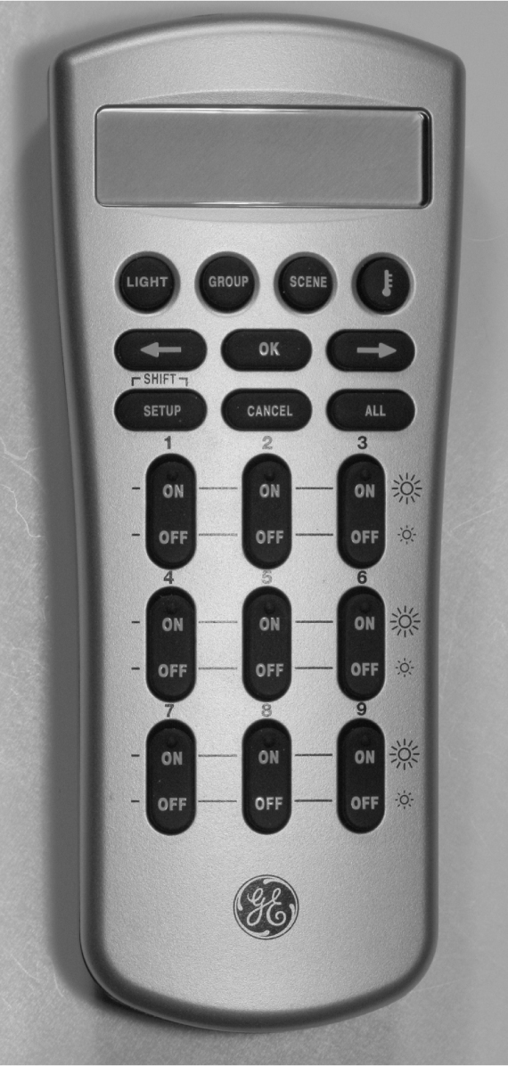
Figure 7–5 Portable Z-Wave controller.
The static controller is another subtype, and it so named because its logical location is fixed at the time of the initial network configuration. It is usually powered from the AC mains and constantly listens for network traffic. A static controller can serve as a secondary controller in an advanced network configuration. The current network configuration may be stored in it, and if so, it is known as a Static Update Controller (SUC).
More often, the role a static controller plays is to serve as a bridge between non Z-Wave components such as X-10 devices. In that configuration, the static controller serves as a virtual node between the X-10 device and the Z-Wave network. The network can have up to 125 virtual nodes that help incorporate older technologies into the modern Z-Wave system. Static controllers may also serve as TCP/IP gateways, thus allowing the network to connect to the Internet, if so desired. Finally, static controllers can serve as primary controllers in the configuration where the “normal” primaries act as proxies for the static control. This configuration type is known as an SUC ID Server (SIS). All told, there is an incredible amount of flexibility in Z-Wave network configurations.
The Z-Wave Chip
The original Z-Wave chip was designed and manufactured by Zensys, now known as Sigma Designs. All certified Z-Wave component manufacturers must use this authentic Z-Wave chip in their devices. This ensures that any Z-Wave node properly joins the network and communicates with other nodes produced by other manufacturers. The Zensys chip design is discussed in this section because it forms the basis for the whole Z-Wave concept and is important background to help you comprehend how the RasPi can function as a controller in the network.
A recent Zensys single module is model ZW3102N, containing a ZW0301 chip that uses the venerable 8051 core with a 32-MHz external crystal. This is a hybrid module containing a lot of additional components, including an RF transceiver operating on either the U.S. or European ISM frequency. There is also a built-in digital modem along with a hardware implementation of the network stack operations that were discussed in the previous section. The ZW0301 chip has only 32 kB of Flash memory and a meager 2 kB of SRAM. It operates on a supply voltage range of 2.1 to 3.6 V and consumes a maximum of 36 mA when transmitting. Figure 7–6 is the block diagram of the ZW3102N, showing all the components that constitute this module.

Figure 7–6 Block diagram of the ZW3102N Z-Wave module.
The ZW0301 microcontroller chip discussed above is also shown in the block diagram. It has several of the standard functions that have been discussed in previous chapters, including the SPI and UART serial interfaces. The chip also has timers, interrupts, a watch-dog monitor, power management, and brownout detection. It has a four channel, 12-bit ADC, a pulse-width-modulation controller, and an enhanced TRIAC control that has zero crossing detection. A total of 10 GPIO lines are available, but some are multiplexed or shared with other I/O functions.
The ZW3102N module is very small; Fig. 7–7 is a photo of it compared to a U.S. 25-cent coin.
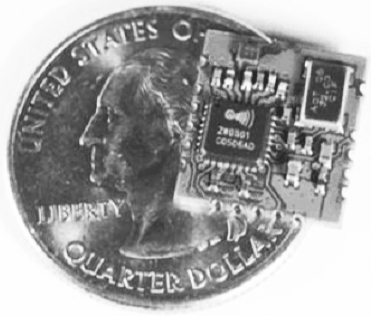
Figure 7–7 ZW3102N module compared to a U.S. 25-cent coin.
The module does need an external antenna and a few capacitors and inductors to complete a Z-Wave device installation. The software is fixed in the flash memory and is not available for examination or modification. This is where this RasPi project will open up the Z-Wave network so that you have a chance to experiment with various configurations and monitor network traffic. But first, I would like to demonstrate a simple Z-Wave network that uses a portable controller (Fig. 7–5) along with two nodes, one being the duplex outlet (Fig. 7–4) and the other being an outdoor module shown in Fig. 7–8. Notice the black button located on the top of the device in Fig. 7–8. The user presses it to join the device to the network when prompted by the controller menu.
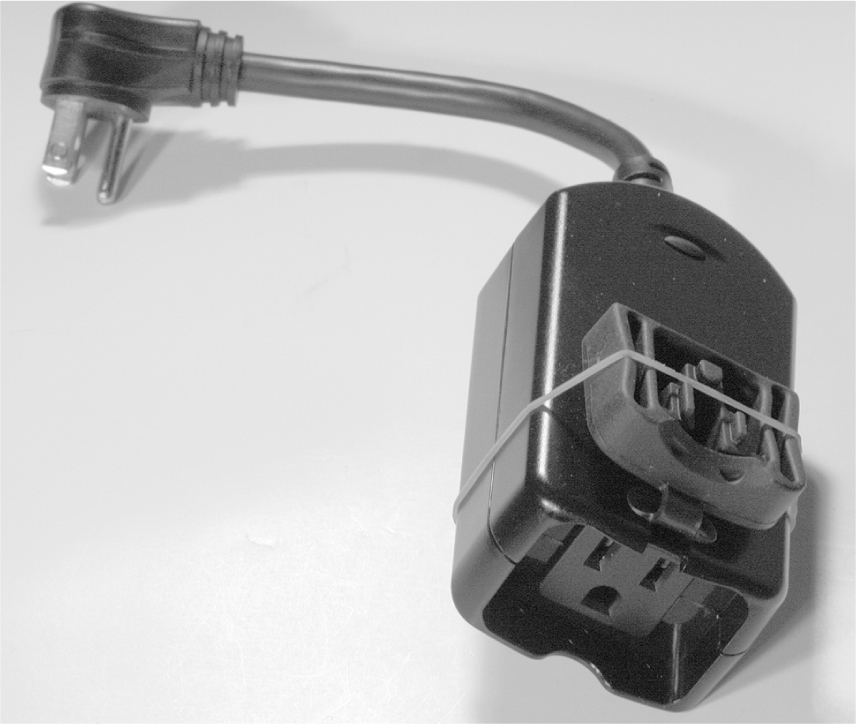
Figure 7–8 Z-Wave outdoor module.
Notice the black button located on the top of the device in Fig. 7–8. The user presses it to join the device to the network when prompted by the controller menu.
My test network slaves will be made up of the duplex outlet and the outdoor module, each controlling a small table lamp. The duplex outlet will actually be connected to a power cord plugged into a regular outlet for this temporary test arrangement. Figure 7–9 shows the test setup on my dining room table.

Figure 7–9 Z-Wave test system.
At first, I arbitrarily assigned a device number 4 to the duplex outlet and a device number 8 to the outdoor module. I then proceeded to turn the lamps on and off, and everything worked just fine. I was also able to control both devices simultaneously by selecting the “All” mode on the remote.
The next part of the test was a bit harder, as I have a smaller home with an open plan layout, meaning fewer interior walls than in the average cape-style home. I was finally able to place the outdoor module device in the basement and the duplex outlet on the first floor and then operated the controller in a second floor bedroom. I was not able to turn on the basement module without having the first-floor module plugged in. This proved that the first-floor module was digipeating and forwarding the control packets to the module located in the basement. The controller showed “Failure” on its LCD screen with the first-floor module unplugged, which indicated that no ACKs were being received. Obviously, no NACKs could be sent, since the first-floor module was unpowered and the basement module was out of range.
Setting up the test arrangement was an extremely simple process, which shows how well the high-tech Z-Wave network functions in the “background,” while also providing the homeowner with a very easy and useful interface. But that’s not what we are after. I want to demonstrate how the RasPi interfaces with a Z-Wave network and what “neat” experiments can be accomplished.
RasPi and Z-Wave Interface
Connecting a RasPi to a Z-Wave network requires the use of a Z-Wave USB dongle. One such device made by Aeon Labs, called the Z-Stick, is shown in Fig. 7–10.

Figure 7–10 Aeon Labs Z-Stick.
The Z-Stick incorporates a Zensys module and a USB interface chip along with some additional firmware to make the two components work together. It also has an internal rechargeable battery that enables the storage of firmware updates and configuration data. The Z-Stick has three operating modes that you should know:
1. Inclusion—This mode adds or includes Z-wave devices into the network. To add a device:
a. Unplug the Z-Stick from the USB connector.
b. Press the large button on the Z-Stick. The Z-Stick LED will start to blink slowly.
c. Go to the device that you wish to add (while continuing to press the large Z-Stick button) and press and release the device’s button.
d. The Z-Stick LED will blink rapidly for several seconds, then glow steadily for three seconds, and finally return to a slow blinking state. The device has been added to the network.
2. Removal—This mode will remove or exclude Z-wave devices from the network. To remove a device:
a. Unplug the Z-Stick from the USB connector.
b. Press and hold the large button on the Z-Stick for about three seconds. The Z-Stick LED will start to blink slowly and then transition to a fast blink.
c. Go to the device that you wish to remove (while continuing to press the large Z-Stick button) and press and release the device’s button.
d. The Z-Stick LED will then glow steadily for three seconds and finally return to a fast blinking state. The device has been removed from the network.
3. SerialAPI—This is the mode where the Z-Stick acts as the portal between the RasPi and the Z-Wave network. Simply plug it into a powered-hub USB connector. The RasPi probably does not have sufficient power for the Z-Stick. The RasPi software will now take control of the Z-Wave network.
I now have to take a brief detour from the Z-Wave to introduce the SSH login process, since I use that in establishing the control software environment.
SSH Login
In this section, I will show you how to log into the RasPi by using a network connection, as I mentioned in Chap. 5. The Wheezy Linux distribution, as well as many others, includes a great service known as SSH, short for Secure Shell. It is a network protocol that uses cryptographic means to establish secure data communication between two networked computers connected via a logical, secure channel over a physical, insecure network. SSH uses both server and client programs to accomplish the connection.
One of the questions you will be asked when first configuring your RasPi is whether or not to start sshd upon bootup. I recommend that you answer “yes” as that automatically starts the SSH daemon each time you start the RasPi. The second portion of the connection is the client program, which is highly dependent upon what type of computer you are using to connect to the RasPi. I recommend using putty.exe, since most readers will be using a Windows®-based machine. putty is freely available from a variety of Internet sources, so I would recommend a Google search to locate a good download mirror.
You should see the Fig. 7–11 screenshot, assuming that you answered “yes” to the sshd question and have downloaded and are running putty on a Windows-based computer connected to the same network that connects to the RasPi. Don’t be concerned with the host name that appears in the screenshot; I will get to that shortly.
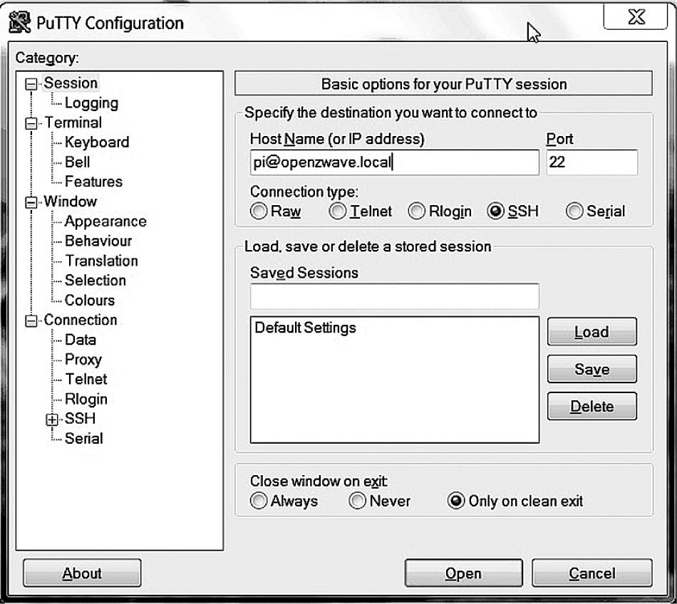
Figure 7–11 putty screenshot.
When you click on the Open button at the bottom of the putty screen, you will see in Fig. 7–12, a screenshot of a RasPi terminal window asking, in this case, for a login password.

Figure 7–12 Raspberry Pi terminal window.
At this point, you are in a RasPi terminal window session. It is absolutely no different from looking at a monitor connected directly to the RasPi and using a locally connected keyboard and mouse. This transparency is what makes SSH so great—it allows you to login remotely to the RasPi without being concerned with any minutia about the connection. You may type in any normal command and have the RasPi respond as appropriate.
I will now return to the Z-Wave control software discussion, now that you are a bit familiar with SSH.
Open Z-Wave Software
I took a very easy approach to implementing the control software between the RasPi and the Z-Wave network. I used a prebuilt Wheezy Raspian image kindly made freely available by Thomas Loughlin at http://thomasloughlin.com/new-open-zwave-image-for-raspberry-pi/. Simply download the image and create a new SD, card using the procedures discussed in Chap. 1. While Thomas has carefully detailed the steps required to get the RasPi working with a Z-Wave network, I will paraphrase and use some figures to help clarify the somewhat involved process.
I used a “headless” approach, meaning I logged into the RasPi using putty. Headless is a bit of network jargon meaning you don’t need a local monitor or keyboard for the RasPi because you will login remotely using the RasPi as a server. The step-by-step procedure for starting the Z-Wave RasPi network is:
1. First add one or two devices to the network as described above. This establishes a beginning configuration that enables you to see and control some devices.
2. Plug the Z-Stick into a powered hub connected to an unpowered RasPi that has the downloaded Open Z-Wave image.
3. Power on the RasPi and wait a minute or so. Remember, we are running headless and are not looking at a monitor screen connected to the RasPi.
4. In the opening putty screen, enter

as a host name. (Fig. 7–11)
5. The password is the regular one,

6. A terminal window (Fig. 7–12) will appear.
7. You are now ready to take one of two approaches to monitor and control the Z-Wave network.
lightscontrol Server
One of two server applications may be run at this point. The first is a web app named “lightscontrol” that was created by Conrad Vassallo and can be downloaded from the website, http://conradvassallo.com/category/open-zwave-controller/. This will be the one that I use. The second approach is a bare bones server app that Thomas created to test the Z-Wave network. I will discuss that server after demonstrating the lightscontrol server. All you need to do to start this service is type the following at the command line prompt:

This starts the lightscontrol server. Figure 7–13 shows the lengthy preamble to the lightscontrol server web app.
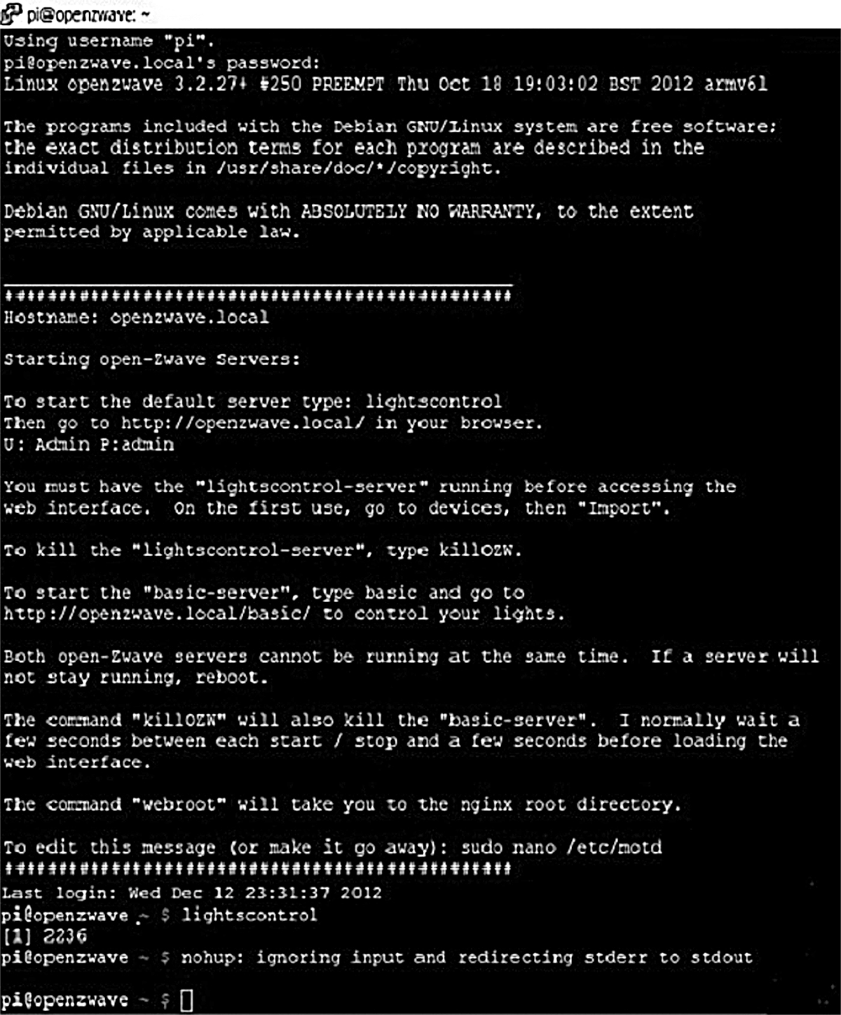
Figure 7–13 lightscontrol web server preamble screenshot.
Now, you should minimize the terminal control window, keeping in mind that there is still an underlying active SSH connection that will allow you to input commands to the RasPi. We are going to need putty after experimenting with the first web server. Next, open a browser and enter this for the URL:
This should take you to the initial lightscontrol server page, as shown in Fig. 7–14.

Figure 7–14 lightscontrol server page.
In my case, I had initially set up one device, a GE outdoor power module controlling a lamp, as I discussed earlier in the chapter. Table 7–4 shows the web page attributes for this device.
Table 7–4 Z-Wave Device Attributes

Clicking on the web page ON and OFF buttons turned the corresponding Z-Wave controlled lamp on and off, thus confirming that all the software and network connections were properly operating.
I have included some screenshots of the web app configuration pages to help illustrate how to configure a Z-Wave network to support typical home automation tasks. There is no professional documentation provided with this open-source project, which is often the case, but I am not complaining and am completely appreciative of the tremendous unpaid effort that goes into such project development done for the general good.
Figure 7–15 is a screenshot of the Scenes web page where one or more devices can be grouped collectively to support a common event happening in the home, such as Wake Up, TV, Kids Sleeping, etc.

Figure 7–15 Scenes web page screenshot.
Figure 7–16 is a screenshot of the Scheduled Events page that works in conjunction with the Scenes page, where the actual device times that support a specific scene may be programmed.

Figure 7–16 Scheduled Events web page screenshot.
My recommendation is to simply experiment with the web app, determining the appropriate inputs to the various pages in order to execute the desired automation sequences. Figuring out the web page inputs should not be a very hard task for you given that you already have reached this stage in building a RasPi home automation system and have successfully loaded and run all the support software. Mr. Vassallo has stated in his blog that the software is still evolving, so don’t be surprised if a better, perhaps somewhat easier, version is developed and put in the public domain.
“basic” Server
The second approach mentioned above is to use the “basic” server that Mr. Loughlin created to test the Z-Wave network functions. In order to do this, you must first kill the lightscontrol server that is currently running, since there cannot be two Z-Wave servers running concurrently. You can also close the browser at this time; it will need to be reopened, however, once the next service is started. Kill the current web service by typing

at the SSH command line. This is the reason why I did not want you to stop running putty.
To start the “basic” server, simply enter the following at the command line:

Once that is done, minimize putty and open the browser going to this website:

This should take you to the “basic” server page, as shown in Fig. 7–17.

Figure 7–17 “basic” server web page.
All devices that have been added to the Z-Wave network and stored in the Z-Stick memory will be displayed on this page. As you can see, the only device displayed is the outdoor power module that was shown in the previous web server demo. The light may be turned on and off by clicking on the icon. There is no provision for setting Scenes or preprogrammed times, as this is just a very functional web test app. The essential device attributes are shown as text in the middle of the page.
I next wanted to test this system to see how a different device type would be accommodated. To do this, I shut everything down and then added a new device to the network. This was a battery-operated, Z-Wave enabled motion sensor, as shown in Fig. 7–18.
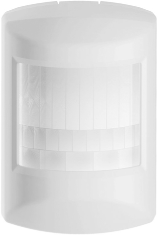
Figure 7–18 Battery-operated, Z-Wave motion sensor.
I next restarted the “basic” web service and loaded the appropriate web page. Figure 7–19 shows this new page with both the outdoor module and the motion sensor displayed.

Figure 7–19 Revised “basic” server web page.
The motion sensor sends data back to the Z-Stick, which I confirmed by waving my hand in front of the sensor and observing that the state shown on the sensor window changed from off to on. Note, I did have to reload the page to observe this change. Also, the essential device attributes shown on the page reflect the selected device.
Summary
I started this chapter with a definition of home automation and provided a list of representative tasks that would fall under the broad umbrella that comprises home automation.
Next followed a discussion of the underlying base technologies that support home automation implementations. I provided a rationale for selecting the Z-Wave protocol: it is a modern, highly flexible system that is very easy to configure and lends itself quite well to a simple RasPi interface connection.
Two representative Z-Wave devices were next described along with a working, small-scale Z-Wave network. Then we conducted a network demonstration by using a commercial remote control device.
The core Z-Wave chip was discussed to provide you with a better understanding of how the overall network functions and how devices are highly dependent upon the chip functions, which can be added seamlessly to the network.
The Z-Stick that enables the actual RasPi to Z-Wave interface was shown along with the driver software. However, before discussing the software, I showed you the highly useful SSH remote login procedure.
The open Z-Wave software package was shown with two variations for the web application side: 1) lightscontrol and 2) “basic.”
Some simple tasks such as turning a lamp on and off were demonstrated as well as the ability to sense motion in a room.

