
Dynamics is the second primary aspect of the UML. Dynamics has to do with how values or states of objects change over time. The UML allows you to model both the specification of behaviors of individual objects (including systems, subsystems, and components) and the capturing traces of interactions among many objects working together. The former behavior is usually captured in statecharts or activity diagrams, while the latter is normally captured in sequence or timing diagrams.
Notation and Concepts Discussed | ||
|---|---|---|
Types of Behavior | States | Interactions |
Actions | Protocol State Machines | Sequence Diagrams |
Activities | ||
Statecharts | Activity Diagram | Timing Diagrams |
The previous chapter presented the structural elements defined within the UML—things like classes, objects, interfaces, ports, subsystems, and components—and how structural views of the system could be constructed from assemblies of these elements. The other pillar of object-oriented modeling is the specification of dynamic behavior. Behavior binds the structure of objects with their attributes and relationships so that objects can meet their responsibilities. Ultimately, actions implement an object's behavior, and the UML provides several approaches for linking action executions. One approach is to put the actions in the methods of classes, and the invocation of these actions takes place using the normal rules of the implementation action language. Common action languages are C, C++, Java, and Ada. Another approach for constraining these primitive actions into permissible sequences is through the use of activity diagrams—a generalized kind of flowchart that allows us to specify action execution, branching, looping, concurrency, and so on. The last primary facility in the UML for specifying action sequences is with state machines, especially when the object is “reactive,” that is, its behavior is executed in response to received events. This chapter discusses these concepts in some detail.
The behavioral specification approach defines the behavior of individual elements (Classifiers). We must also concern ourselves with collaborative behavior—that is, behavior of collections of instances that work together to achieve a common, higher-level purpose, such as the realization of a use case. We model the behaviors of collaborations using interactions. Such interactions may be completely synchronous, relying on method calls, completely asynchronous, using various message-queuing schemes, or a combination of the two. The UML uses interaction diagrams such as sequence, collaboration, and timing diagrams to capture and represent interactions. Additionally, activity diagrams, with activities bound to swim lanes, may also specify interactions among objects represented by those swim lanes.
In the previous chapter we discussed the definition of structural elements of the system—classes and objects (in the small), and systems, subsystems, and components (in the large). As developers, we are usually even more concerned about how these structural elements behave dynamically as the system runs. Behavior can be divided up into two distinct perspectives—how structural elements act in isolation and how they act in collaboration.
In the UML metamodel, Elements are the primary structural elements that have behavior. Classifiers (which are types of Elements) also have BehavioralFeatures, such as Operations, and their realization, Methods. In practice, we are primarily concerned with the specification of the reactive behavior of only certain Classifiers (classes, objects, systems, subsystems, components, and use cases) and certain other Elements (Actions, Operations, Methods, States, Events, Signals, and Transitions).
Logically, behavior of single elements or groups of elements can be modeled as one of three distinct types: simple, stateful, and continuous. All three are important, although the second has a particular importance in real-time systems.
The most common kind of behavior is called simple. The object performs services on request and keeps no memory of previous services. Each action is atomic and complete, at least from an external perspective. A simple object may maintain a collection of primitive data types and operations defined to act on them. A binary tree object, for instance, shows simple behavior. Another example is a cos(x) function. cos(π/2) always returns the same value, regardless of what value it was invoked with before. It retains no memory of previous invocations. This kind of object is also called primitive because it adds no additional constraints on the use of its operations.
An object exhibiting simple behavior always responds to a given input in exactly the same way, regardless of its history. Some examples of simple behaviors are
Simple mathematical functions, such as cosine or square root
A search operation of a static data structure that always starts from the same point, such as the search of a static binary tree
Sort operations
A knob that returns the number of clicks for a given user action
Note that simple behavior is also known as functional behavior, meaning that it defines simple behavior to be a mathematical function. Simple behavior is often modeled using activity diagrams, a topic covered in Section 3.4.8. Simple behavior is composable in the sense that if g(c) = a and f(a) = b, then f(g(c)) = b.
The second type of object behavior treats the object as a particular type of machine, called a finite state automaton or finite state machine (FSM). This kind of object possesses a bounded (finite) set of conditions of existence (state). It must be in one and only one state at a time. An automaton exhibits modal behavior, each mode constituting a state. A state is defined to be a mutually exclusive condition of existence defined by the set of events it processes and the actions it performs. Because objects with state machines react to events in well-defined ways, they are also called reactive objects.
Incoming events can induce transitions between object states in some predefined manner.
A sample-and-hold A/D converter is such an object (see Figure 3-1). It shows the states of
Disabled: In this state, the object is not acquiring data and the hardware inverters are turned off.
Enabled: In this state, the hardware inverters are turned on and the object may be in one of the following states: ready to acquire data, actively acquiring data, or holding data that has been acquired.
Ready: The object is enabled but has not yet begun to capture data.
Sampling: The object is actively acquiring data.
Holding: The object is holding data that it previously acquired.

The statechart semantics and notation are discussed in more detail later in this chapter. Nevertheless, we can see that the state machine controls the sequence of the execution of the actions defined within the statechart. For example, when the object is in the state of Ready and it receives a GetSample event, it initializes a counter attribute to zero and begins the sampling process. When in the Holding state, the object responds to the receipt of a GetValue request event by returning the value held in the object's attribute “value.”
The third kind of object behavior is called continuous. An object with continuous behavior is one with an infinite, or at least unbounded, set of existence conditions. One example is the so-called algorithmic object. This is an object that executes some algorithm on a possibly infinite data stream. A moving average filter performs a smoothing function over an incoming data stream. Objects with continuous behavior are objects whose current behavior is dependent on past behavior and inputs, but the dependency is of a continuous, rather than discrete nature. Fuzzy systems, PID[1] control loops, and digital filters are examples of objects exhibiting continuous behavior. Their current behavior depends on past history but in a quantitative not qualitative way.
All that is required for continuous behavior is that the current output depends on the previous history in a mathematically smooth way.
Although the UML is very expressly a discrete modeling language, it is possible to model continuous behavior by specifying actions on activity diagrams or statecharts. Since the UML doesn't define an action language (although it does define the things that an action language must be able to do), the continuous aspects are, strictly speaking, outside of the auspices of the UML.[2] Nevertheless, people can and do build systems that perform continuous behavior with differential and partial differential equations. This process is discussed in Chapter 10, which covers detailed design.
It is even sometimes appropriate to mix state and continuous behavior. For example, different sets of trajectory differential equations may be used, depending on whether a spacecraft is undergoing launch, achieving orbit, in orbit, or in cruise. Such systems are called piece-wise continuous. The way in which this is normally done is to define a different set of equations (or activity diagram) for each state of the object.
In the UML, Classifiers (specifically BehavioredClassifiers) have behaviors, and one kind of behavior is called an Activity. Activities contain actions, the elemental quanta of UML behavior. Activities provide an execution context for actions, including scope of values (e.g., variables) manipulated by a common set of actions. Activities may be represented textually by an action language or graphically in an activity diagram.
An action takes a (possibly empty) set of inputs and produces a (possibly empty) set of outputs. That is, it is a primitive, simple statement similar in scope to a single statement in a standard source-level language, such as “++X” or “a=b+sin(c*π).” Formally speaking, each input value enters the action on an Input Pin and each output value is sent to an Output Pin; however, for virtually all real modeling, the notions of pins can be safely ignored. It is enough to say that actions take input values and computationally produce a set of output values.
The UML specification identifies a number of kinds of actions, such as the following:
CallOperationAction—. an action that results in the synchronous invocation of an Operation or Method
SendSignalAction—. an action that results in the asynchronous transmission of an event
BroadcastSignalAction—. an action that results in the broadcast of a signal to all target objects in the system
SendObjectAction—. an action that sends a copy of a signal object to a target object
PrimitiveAction—. an action that cannot be decomposed into smaller subactions, such as simple mathematical functions
Some types of PrimitiveActions include
CreateObjectAction
DestroyObjectAction
TestIdentityAction
ReadSelfAction
ReadStructuralFeatureAction
WriteStructuralFeatureAction
ClearStructuralFeatureAction
AddStructuralFeatureValueAction
RemoveStructuralFeatureValueAction
LinkAction (e.g., read, write, create, destroy)
VariableAction (e.g., read, write, create, destroy)
AcceptEventAction
LoopAction
ConditionalAction
This all may seem confusing (mostly because it is), but if you just remember that actions are meant to describe the kinds of statements you find in standard programming languages, you'll be all right. Actions are normally computationally simple things and, by far, are most commonly represented using an action language. The UML does not define an action language,[3] because most developers want to use the implementation source-level language for the action language in their models. That is, almost all of the time, actions in a UML model are specified in the implementation language of that system. A more abstract action language could be used, allowing the developer to generate code in multiple target languages, but the UML does not define one. There are advantages to using abstract language—independence of the model from the implementation being the primary one—but there are disadvantages as well, such as making the testing and debugging of the system more difficult. Whether the best action language is the implementation language or abstract action language depends on the nature of the application. If the application has a very long lifecycle or will be ported to multiple environments, then an abstract action language is arguably the best choice. If the application will remain on a single platform, if the difficulty of test and debugging the system is high, if it is clear that a single source language will be used in the implementation, or if you'd like be able to work in either the source language or the model, then using the implementation language to specify the actions will be preferred.
Actions are normally specified in one of three places: First, and most common, actions are simply entered into the bodies of methods defined within classes. This enables the generation of both simple and continuous behaviors, although in most action languages continuous behaviors are “discretized” and differential equations are represented using difference equations. Another common place for actions is in statecharts. In statecharts, activities may be specified for execution when a state is entered or exited, when a particular transition is taken, or when special “do activities” are done after the entry activities are executed. Figure 3-1 shows examples of state entry and transition activities that are executed as the object moves from state to state. These activities may be simple textual lists of actions in the action language, or they may refer to activity diagrams for graphical representation.
Actions have “run-to-completion” semantics, meaning that once an action is started it will run until it is done. This does not mean that an action cannot be preempted by another action running in a higher-priority thread, merely what when the context executing that action returns from preemption, it will continue executing that action until it is complete before doing anything else. This means that if an object is executing an action, the action will run to completion even if that object receives events directing it to do something else. The object will not accept the incoming events until the action has completed. For this reason, actions are usually, although not always, short in duration.
Activities do not have run-to-completion semantics. Activities may be interruptible between their contained actions.[4] An object executing a “do activity” may receive an event that triggers a transition in its state machine, exiting the state and terminating the activity. Thus, the UML allows the modeling, at a primitive level, of both interruptible and noninterruptible behaviors. Activities are most often represented on activity diagrams and are composed of sequences of action executions that proceed largely through completion (i.e., they progress by completing actions as opposed to waiting for events of interest).
An operation is a specification of an invocable behavior of a Classifier, whereas a Method is the implementation of an Operation. That is, an Operation is a specification of a Method. Operations are synchronously invoked with CallActions and are logically associated with CallEvents in the UML metamodel. Operations have typed parameter lists, as you might expect, and can return typed values. It is common to use an operation call as an action on a state behavior.
Modeling of the behavior of an operation is done primarily in two ways. First, and most common, is to simply list, in a textual fashion, all of the actions comprising the internals of the operation or method, such as “write the code” for the method. The second, which will be described shortly, is to model the operation with a synchronous state machine or with an activity diagram.
In state machines designed by traditional structured methods, the portion of the system exhibiting the state behavior is not clearly defined. Some set of functions and data collaborate together in a way that lends itself to finite state modeling, but generally this set is only vaguely defined. In object-oriented methods, the programmatic unit exhibiting state behavior is clear—only Classifiers, such as systems, subsystems, components, classes, and use cases, can define state models, and only instances of those Classifiers can execute state machines.
The two fundamental concepts of statecharts are State and Transition. A State is a condition of existence of an instance that is distinguishable from other such conditions. States that are disjoint are called or-states because the object must be in one such state or another.
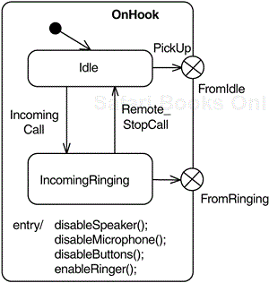
Figure 3-2 shows a simple class diagram for a PBX telephone system. We see that Telephones associate with Lines, which in turn associate with Connections and Call Routers. The lower part of the figure shows the statechart for the relatively simple class Telephone.

States are shown as rounded rectangles. As mentioned earlier, states are conditions of existence of the class they define. In this case, the instances of the Telephone class may be in the or-state of “On Hook” or “Off Hook.” These are or-states because the Telephone must be in one of them but cannot be in both of them. While the Telephone is in the On Hook state, it may be either in an Idle state or in a Incoming Ringing state (because a remote caller is calling). These are also or-states but are nested within the composite state On Hook. When the Telephone is in the On Hook state, it must be in one of these nested substates, and so these nested states are also or-states, but their context is the enclosing composite state.
Nesting of states is a very straightforward idea. If you were at the Embedded Systems Conference[5] in San Francisco and I called you and asked you if you were in California, you'd say “Yes” because you are in the state of California. If I ask if you were in San Francisco, you might say “Yes, but next week I'll be in LA, so I'll still be in California.” What you're saying is that you're in the nested state “San Francisco” now but later you'll be in the nested state “LA.” In both cases you'll be in the state of California. Statecharts have a built-in operator IN() (sometimes called IS_IN()) that you can apply to a stateful object, and it will return TRUE if the object is in that state when the operation is invoked. Thus, if the Telephone is in the state of Incoming Ringing, IN(Incoming Ringing) will return TRUE, but so will IN(On Hook). IN(Idle) and IN(Off Hook) will both return FALSE in this case.
Similar to the On Hook state, the Off Hook state also has nested substates. While the Telephone is Off Hook, it can be in one (at a time) of its nested states—it may be in a Dialing, Outgoing Ringing, Busy, or Connected state. Note that when the instance is in the Off Hook state, if a Hang Up event is received, then the object transitions to the On Hook state regardless of which substate of Off Hook was active. This is one of the ways that nested simplifies state machines, because in a “flat” state machine this transition would have to be drawn four times to have the same semantics, one from each of the states nested within Off Hook.
The object may execute actions when a state is entered or exited, when an event is received (although a transition isn't taken), or when a transition is taken. Figure 3-3 shows actions on both state entry and exit for the Ready state. This is shown with the key word entry, followed by a slash (/) and a list of the actions. The actions may be any kind of action defined in the UML—call actions (to invoke a method defined in this or another object), event generation, or even the execution of a primitive action statement such as ++x. Entry actions are executed whenever the Ready state is entered, regardless of which transition path was taken to get there, whether it is the transition invoked by the event evToReady or the transition-to-self invoked by the event evRedo. The Ready state also has exit actions that are executed whenever the object leaves this state regardless of which transition path is taken to exit the state. The syntax is the same as for entry actions except for the key word exit.

Notice in Figure 3-2 that the associated Line object is notified when the phone transitions from the Off Hook to the On Hook state by the generation of a DisconnectSignal event. This action is executed whenever the object leaves the Off Hook state regardless of which transition path is taken. Note that transitions among the internal nested states of Off Hook don't cause this action to execute because the object doesn't leave the enclosing composite state Off Hook until it transitions to the On Hook state.
Internal transitions are similar to “transitions to self”—that is, transitions that begin and end on the same state. However, with a transition to self, both the exit and entry actions are performed in addition to the actions specified on the transition itself. In the case of the transition to self initiated by the event evRedo in Figure 3-3, the order of execution of actions is
Exit actions, such as ––x; y = cos(sqrt(x))
Transition actions, such as cout << “redoing...” << endl
Entry actions, such as ++x; y = foo(x^2)
An internal transition executes neither the exit nor the entry actions of the state; in response to the specified event, it executes only the particular actions identified for the internal transition. In Figure 3-3, state Ready has two internal transitions, one of the event keyPress and another on the event knobTurn. If either of these events occur when the object is in that state, then only their respective actions are performed, not the entry and exit actions for the state.
The activities (and their nested actions) defined for state entry or exit, or specified on transitions, are simple run-to-completion behaviors. States may also specify do activities, as discussed in the previous section. Such activities are not run-to completion; in fact, when such an activity is executing in a state and the object receives an incoming event that is processed while in that state, the activity aborts and the specified transition is taken. Do activities are specified with the syntax
do activity-name
where activity-name is the name of the activity to be executed. Such activities may be only specified within states and begin after the completion of that state's entry actions. In practice, activities are only rarely used in statecharts, and most of the primitive behavior executed by a statechart is expressed in various actions.
Sometimes an object may be in a state where processing an event would be inappropriate, but you'd like that object to remember that the event occurred and process once it transitions to the next state. The defer clause allows you to specify exactly that. Following the key word defer is a list of events to be deferred. The semantics of the defer clause are that, should one of the deferred events occur, it will not be processed but it will be remembered. As long as the object transitions to states where that event is in a defer clause, the event will continue to be remembered. As soon as the object transitions to state where the event is no longer deferred then it will be processed; that is, it will either fire a transition, fire an internal transition, or be discarded.
Transitions are directed arcs beginning at the starting state and finishing at the target state. Transitions usually have named event triggers optionally followed by actions (i.e., executable statements or operations) that are executed when the transition is taken. The event signature for a transition is of the form
event-name '(' parameter-list ')' '[' guard-expression ']' '/' action-list
All of these fields are optional. A transition without an event signature fires as soon as the state is entered (i.e., its entry actions have completed) or, if there are do activities defined within the state, as soon as those activities complete. That having been said, most transitions do specify at least the event-name. Table 3-1 details the fields of the event signature.
Table 3-1. Transition Syntax
Field | Description |
|---|---|
Event-name | The name of the event triggering the transition. |
Parameters | A comma-separated list containing the names of data parameters passed with the event signal. |
Guard | A Boolean expression that must evaluate to TRUE for the transition to be taken. The expression should not have side effects such as assigning values. |
Action list | A list of operations executed as a result of the transition being taken. These operations may be of this or another object. |
The UML defines four kinds of events:
SignalEvent: An event associated with a Signal. A Signal is a specification of an asynchronous communication, so a SignalEvent is an event associated with an asynchronously received signal.
CallEvent: An event associated with a Call. A Call is a specification of a synchronous communication, so a CallEvent allows one object to affect the state of another by invoking one of its methods directly.
TimeEvent: An event associated with the passage of time, usually indicated with either tm(<duration>) or after(<duration>). Almost all TimeEvents are relative time; that is, they specify that the event will occur after the object has been in the specified state for at least <duration> time units. If the object leaves that state before the timeout has elapsed, then the logical timer associated with that duration disappears without creating the timeout event.
ChangeEvent: An event associated with the change in value for an attribute. It is rarely used in software applications; however, when a state attribute is memory mapped onto a piece of hardware, it can be used to indicate that the memory address changed value.
Events may specify formal parameter lists, meaning that events may carry actual parameters. In Figure 3-2, for example, we could have show the digit event pass a value indicating which key was pressed, such as 0 or #, by using the transition
digit(key: keyType)/ show(key)
Some tools use alternative notations, such as not referring explicitly to the parameter in the parameter list but using a special pointer called params to point to the passed parameters. In this case, the full transition might be something like this:
digit/show(params->key)
In either case, the action show accepts the parameter key and displays it on the screen. In order to generate this event from another object, you might use a helper macro in a tool such as Rhapsody with
GEN(digit(EnterKey))
where EnterKey is of the same type as params->key. Alternatively, if the event is synchronous, you might just a method on the object to send a CallEvent, as in
myTelephone->digit(key)
which dereferences a pointer called myTelephone to an instance of class Telephone, and calls a method called digit passing the appropriate parameter.
Sometimes a transition will appear without a named event in its signature. This is called an anonymous transition or a completion event. Such a transition fires when the predecessor state is entered; that is, when the state's entry actions have completed and the activities, if any, have completed. If there are no activities defined within the state, then the anonymous transition fires as soon as the state's entry actions have completed. If there are activities, and another event that fires another transition comes in before the activities complete, then the activities are aborted and the named transition is taken. This is the primary difference between actions (which are run-to-completion) and activities (which are interruptible).
Some examples of legal transitions are
E1
E1 [x < mySensor->Value)]
E1 (x: float) / y = filter(x*100)
E1 (x: float, y:long) [abs(x) > abs(y^2) > 0] / result = x / y
[mySensor->IS_IN(Has_Data)] / value =filter( mySensor->get Value())
/ y = sqrt(x^2 + y^2); z = 2*y - 3
The first transition specifies only an event. The second specifies an event with a guard. The third passes a parameter and then uses the value of that parameter in an assignment computation. The fourth combines a named event with two passed parameters, a guard, and an action. The fifth has no named event trigger but does have a guard and an action. The sixth just specifies an action list (containing two actions) but not a named event or a guard.
The guard expression is a Boolean expression, enclosed between square brackets, that must evaluate to either true or false. Care must be taken to ensure that guards do not have any side effects, such as changing an attribute's value. Typical guards will specify invariants that should be true before a transition is taken, such as [x>0] (returning TRUE that the object's attribute x has a value of greater than zero) or [myLine->IS_IN(Idle)] (TRUE when the associated object referred to via the myLine pointer is currently in the Idle state). Guards are a very simple way to ensure preconditions are met, such as that the door is closed before powering the emitter in a microwave oven (an important consideration for repeat business!).
Actions do the real work of a state machine. The state machine is important because it defines the possible set of sequences of action executions under a (possible large) set of circumstances. Nevertheless, the actions are where the object actually does something interesting in the real world.
The order of execution of actions is important. The basic rule is exit-transition-entry. That is, the exit action of the predecessor state is executed first, followed by the actions on the transition, followed by the entry actions of the subsequent state. In the presence of nesting, exit actions are executed in an inner-to-outer fashion, while entry actions are executed from outer-to-inner. In the example of Figure 3-2, when taking the transition “pick up” while the object is in the state IncomingRinging the order of action execution would be
IncomingRinging exit actions
On Hook exit actions
Pick up transition actions
Off Hook entry actions
Connected entry actions
We have already discussed the semantics of or-states; if A and B define the set of possible or-states of a specific context, then the object must be either A or B at all times. It cannot be in both and it cannot be in neither. The UML also has the notion of and-states to model conditions that must be simultaneously true and independent.
Statecharts provide a very clear yet succinct representation of and-states, as shown in the simple Microwave Oven object example in Figure 3-4. This object exhibits four independent state aspects—cooking, timing, display, and door monitoring. Obviously, for safe and effective operation, all these activities must go on simultaneously. These independent state aspects are called and-states and are separated with dashed lines. The and-states are often referred to as regions, or orthogonal regions. And-states are always substates of an enclosing composite state.

Each of the and-states is named and operates independently of the others, as if they are concurrent—and in an important sense they are. What do we mean by concurrent in this case? Basically the same as in other cases—that the processing within an and-state proceeds independently from processing in other, peer and-states, and you cannot in principle predict which and-state will process an event first. Each active and-state basically receives its own personal copy of any event received by the object and is free to independently process or discard that event, as appropriate. This means (and we'll see why this is important in a moment), that multiple and-states may process the same event when an event is received by the object.
The complete “state” of the object is the cross-product of all of its currently active and-states. The Microwave Oven may be, for example, in the state of [Emitting, DisplayingCookTime, DoorClosed, and Waiting ForTick], or it may be in the state of [EmitterIdle, DisplayingTimeOf Day, DoorOpen, and WaitingForTick]. And-states make the specification of independent aspects of a stateful object much more parsimonious as compared with normally Mealy-Moore (M&M) state machines. M&Ms don't have the notion of and-states and so must display the state space as an explicit enumerated list, giving rise to states named “Emitting-DisplayingCookTime-DoorClosed-WaitingForTick,” “NotEmitting-DisplayingCookTime-DoorClosed-WaitingForTick,” and so on. This is obviously a long list, making the creation of the state diagram in Figure 3-4 with M&Ms a daunting task.[6]
The addition of and-states to your state-modeling paradigm is very powerful, but it also creates new questions. For example, how do I synchronize and communicate among peer and-states when necessary?
There are four primary ways that and-states can communicate, synchronize, and collaborate. Remember, first of all, that it is the object and not the state that receives incoming events. When an object receives an event, it is acted upon by all of its active and-states and that action may be to take a transition, execute an “internal transition” (execute a set of actions without changing state), or discard it. It is as if each active and-state receives its own copy of the incoming event to do with as it pleases, independently of all the other and-states. This is a kind of contained “broadcast” in that all active and-states receive each event as it is received by the object.
The second means for and-state collaboration are propagated events. Propagated events are events that are sent as the result of a transition being taken in one and-state or object. Remember, the UML defines two different kinds of actions that can be used to create such events—Send Actions (resulting in SignalEvents) and CallActions (resulting in CallEvents). Call actions must be used carefully as propagated events as they execute in the same run-to-completion step as the initiating event.
Another means for and-state collaboration is with the IS_IN( ),[7] which returns TRUE if another and-state is currently in the specified nested state. This allows for and-state coordination. In Figure 3-4, we see the IS_IN() operator used in guards; for example in the Cooking region the evCook transition is protected with an IS_IN(DoorClosed) guard to ensure that we don't cook the chiefs!
The UML defines a number of different pseudostates, as shown in Figure 3-5. Pseudostates indicate the use of special semantics; they are not in any way states, but they are used as annotations of some defined special state chart behaviors. The UML 2.0 has removed a few of the lesser used pseudostates, such as the synch pseudostate, and replaced the stub pseudostate with the entry point and exit point pseudostates.
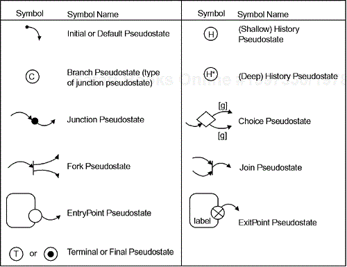
Briefly, these pseudostates are as follows:
Initial or default: Within a composite state context, the initial pseudostate indicates which substate is initially entered as a default. The initial pseudostate may be overridden, either by transitioning directly to a different nested state or with the history pseudostate.
Terminal or final: The final state indicates that the enclosing composite state is terminated. If the final state appears in the outermost level of nesting, it indicates that the object no longer accepts any event, usually because it is about to be destroyed.
Junction: Vertices used to join together multiple transitions, or to divide a transition into a set of sequential transition segments. Regardless of the number of transition segments connected, they all execute in a single run-to-completion step.
Branch or conditional:[8]. The branch pseudostate indicates a set of possible target or-states, one of which will be selected on the basis of a guarding condition. The branch pseudostate is nothing more than a junction with guards on exiting transition segments. However, it was called out in previous versions of the UML with a special icon (usually a ©) and is still indicated using an independent icon by many modeling tools so it is separately identified here.
Choice point: A choice point is a kind of junction that executes its action list before going on to the next transition segment. This allows actions bound to the first transition segment to execute prior to the evaluation of subsequent guards.
Shallow history: This pseudostate indicates that the default state of a composite state is the last state visited of that composite state, not including nested substates.
Deep history: This pseudostate indicates that the default state of a composite is the last state visited of that composite state, including substates nested arbitrarily deeply.
Join: A connector that joins multiple incoming transitions from peer and-states into a single transition. This is not the same as a junction. (And-states are discussed in Section 3.4.2.)
Fork: A connector that branches into multiple transitions, each entering a different and-state, from a single input transition. This is not the same as a branch because in a branch only a single transition activates; in a fork, all outgoing transition segments activate.
Entry point: An entry point is used in conjunction with a composite state to serve as a connector between its nested states and its peer states. It is usually not used unless the nested states are hidden and put on a separate state diagram.
Exit point: An entry point is used in conjunction with a composite state to serve as a connector between its nested states and its peer states. It is usually not used unless the nested states are hidden and put on a separate state diagram.
Whenever a class defines a statechart there is always the question of what state the object starts in when it is created. This is indicated with the initial (or default) pseudostates. This special annotation is a transition with a ball at one end. In Figure 3-2, the Telephone enters the state On Hook when it is first created. Because composite states have states nested inside, it must also contain an indication as to which nested state is the default (Idle, in this case; Dialing, in the case of the Off Hook state). When a transition terminates on the composite state, the default pseudostates inside the composite state indicate which nested state is entered initially. The default nested state can be bypassed by drawing a transition directly to a different nested state if desired, as illustrated by the transition from the Incoming_Ringing state to the Connected state.
To be well formed, a statechart must have an initial pseudostate to specify the starting state when an object is created. Additionally, each composite state must indicate the initial pseudostate for its nested states, and each and-state region must have an initial pseudostate as well.
Transitions may be broken up into segments with the junction pseudostate. A complete transition path may have only a single event associated with triggering it, but they may join, to share actions. Junctions may have multiple incoming transitions as illustrated in junction pseudostate 1 in Figure 3-6. Both transitions share the common branch of the exiting transition. Junction pseudostates may also have multiple exiting transitions, provided they are all guarded, as shown with junction pseudostate 2 in the same figure. The guard selects which transition path will be taken. It is important to note that if all the guards evaluate to FALSE, then no transition will be taken from the originating state—the state machine must have a complete, valid path to a subsequent state before an event may trigger a transition. Note that in the figure, if state 1 is the current state and the event ev2 occurs, at least one of the guards exiting junction pseudostate 2 must evaluate to TRUE or the event will be discarded without executing any action; that is, before any actions will be taken, z must either be greater than 10 or less than 1.
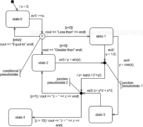
Older UML use the conditional pseudostate (©) to indicate conditional branching; however, in later revisions of the UML, the junction pseudostate included the conditional pseudostate because any junction may have multiple guarded exiting transitions. The figure shows a typical use of the conditional pseudostate as well as a semantic trap. Can you spot it?
The question is, starting in state 0, when the event ev1 is received, to what state will the object transition? Most people think (incorrectly) that the object will transition to state 2 because of the preincrement of x in the event signature action list. However, the guard is evaluated prior to the execution of any actions; therefore the else clause (which evaluates to TRUE when all the other exiting branches all evaluate to FALSE) is taken because at the time of evaluation of the guards, the value of the attribute x is zero.
Another interesting question is what happens if multiple guards evaluate to true. The UML specifies that one of the true branches will be taken, but which one is indeterminate? After all, whichever branch is taken will have a TRUE guard condition. Normally, when multiple exiting transitions fire, it indicates a modeling error, and the model is said to be ill-formed. Don't let this happen to you![9]
Because actions are only executed if a transition is taken, they are not executed before the guards are evaluated. This is because the guards must be evaluated prior to the execution of the actions. Sometimes this is an inconvenient thing to do. In these cases, you should use choice points instead. A choice point is a specialized form of junction used when the result of an action executed during a transition is to be used in a guard. In this case, the actions on the initial segment of a compound transition are executed before checking the guard. The notation for a choice point is a diamond, but otherwise it looks like a conditional pseudostate.
Choice points are dangerous in use because the actions are executed before the guards are evaluated. If the guards should all evaluate to FALSE, then the object is no longer in a valid state. Because of the likelihood of this happening, I recommend that you not use choice points, but use junctions (or conditionals) instead. If you stick with junctions, then the object will always remain in a valid state when the guards evaluate to FALSE.
As we have seen, composite states are decomposed into nested states. The default nested state for a composite state is indicated with an initial pseudostate. When the composite state is exited and later reentered, the same nested state is again reentered. But what if the semantics you want are not to reenter the same nested state but to instead reenter the last active nested state?
The statechart answer is history. The history pseudostate is a letter “H” in a circle. Figure 3-7 shows the different aspects of the history pseudostate. To be activated, the transition must terminate on it, as with the transition from state 0, labeled e1, and the transition labeled e2 from state 1. Both of these transitions terminate on the history pseudostate. The transition labeled e0 from state 0 does not, so the normal default (to nested state a1) is activated whenever that transition is taken. However, if the active state is state a2 when transition e1 is taken, followed by transition labeled e2, then, the object reenters state a2. Of course, when the object is in state a2, it must also be in one of its nested states. Because of the kind of history used for composite state A, the default nested state for state a2 will always be reentered even if the last active nested state was state a24.
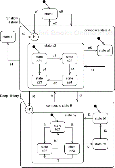
There is another kind of history as well—deep history. Deep history differs in that while shallow history only applies to the immediate level of nested and no deeper, deep history applies through all levels of nesting no matter how deep. Deep history is indicated with a circumscribed H*, and is shown in composite state B. When the current state is state b23, and the object receives an event f1 (taking it to the default state of composite state A) followed by an event f0, the object reenters the state b23. As before, transitions that do not terminate on the history pseudostate don't activate the history semantics.
When a composite state with and-state regions is entered, the default state for each of the regions is entered. But what if you want to bypass those default states under some circumstances? As with many of the other pseudostates, there are special pseudostates for explicitly doing nondefault behavior. In the case of and-states, these are the fork and join pseudostates.
If you want to bypass the default for a normal (or-) composite state you simply draw the transition directly to the desired nested state. However, in the case of entering and-state regions you have multiple branches you'd need to specify. That is exactly what the fork pseudo state does. Unlike with or-states, where multiple branches indicate selection (since only one branch can be taken), the multiple transitions exiting a fork indicate concurrency, at least in the logical sense, because all branches are taken, essentially at the same time. Figure 3-8 shows a fork in use. The default nested states are the InitTool and the InitArm states, and these states are entered when the transition labeled evGo is taken. However, when the transition labeled evContCmd is taken, then these defaults are bypassed and the states orientTool and calculatingPath are taken instead.
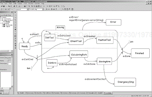
Conversely, the evError transition exits the Moving state, regardless of which of the states nested within the and-state regions are active. If you want to specify a single nested state in one and-state and the other and-states are “don't cares,” then you can initiate a transition from the (single) desired substate, as is done with the evMovementDetect transition leaving the moveArm state; it doesn't matter what nested state is active in the other and-state, when moveArm is active and the object receives the evMovementDetect event, the transition is taken. When you want to specify multiple predecessor states, then you must specify which ones you mean—this means joining multiple branches. That is the purpose of the join pseudostate. In the figure, both positionTool and MoveArm must be active for the transition labeled evDone to be taken. If either of those states is not active when that event is received, then the event is simply discarded. The join can only be initiated by a single event; that is, you cannot join transitions resulting from the receipt of multiple events.
Previously, we've seen that or-states and and-states can be nested within other states. In most cases, the entire state machine will be specified on a single statechart, using whatever level of nesting is called for. In large, complex statecharts, this can lead to diagrams that are difficult to decipher. For this reason, the internal state decomposition of a superstate can be defined on a separate statechart called a submachine. Figure 3-9a shows the same state machine from Figure 3-2, now hiding the internal structures of the OnHook and OffHook composite states. As long as transitions initiate or terminate on the border of the composite state, the defaults are used. For transitions terminating on the composite state, the initial state will be entered; for transitions initiating on the composite state, the transition will be taken regardless of what nested state of the composite is currently active. But what if a transition initiates only from a specific nested or terminates on a nondefault state? How can this be shown?

The answer is to use entry and exit points. These are the circles on the state boundaries shown in Figure 3-9. The empty circles are entry points—they indicate that a transition terminating (from outside the composite state) on the entry point will be delegated to a specific, but not-shown state inside the composite. The circles containing a cross are called exit points. A transition originating from that pseudostate arises from some specific, but not-shown nested state inside the composite.
Figures 3-9b and 3-9c show the internals of the composite states from Figure 9-9a. The entry and exit points are explicitly named so they can clearly specify which transition paths they define. I have used the name of the initiating or terminating state in the name of the entry and exit point labels, but any meaningful label may be used.

UML 1.x was a bit vague on how to interpret the inheritance of state machines when a stateful class was specialized. UML 2.0 is more precise on this matter. In order to ensure compliance with the Liskov Substitution Principle (that instances of subclasses must be freely substitutable for instances of their superclass) some rules must govern the modifications that can be made to an inherited state model:
New states and transitions may be freely added in the child class.
States and transitions defined by the parent cannot be deleted (the subclass must accept all events and messages that can be accepted by the parent).
Action and activity lists may be changed (actions and activities may be added or removed) for each transition and state.
Actions and activities may be specialized in the subclass (i.e., actions may be polymorphic).
Substates may not alter their enclosing superstate (including adding a new one).
Transitions may be retargeted to different states.
Orthogonal components may be added to inherited states.
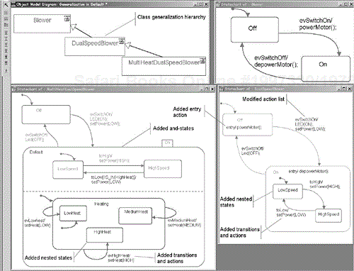
A simple example of inherited state models is provided in Figure 3-10. The class model is shown at the upper left of the figure. The class Blower has a simple on-off state model (shown at the upper right). The evSwitch On transition has a single action in its action list, the function powerMotor(). The Dual Speed Blower class extends the Blower class by adding Low and High speed substates to the On state. Note that the action for the evSwitchOn transition is now changed to the execution of the functions LED(ON) and setPower(LOW). Additionally, the Off state now has an entry action and the action for the evSwitchOff transition has been changed. The Dual Speed Multiheat Blower class continues the specialization by adding three heat settings as an orthogonal component to the Low and High states added by the previous subclass. Also action lists have been changed. Nevertheless, the generalization taxonomy is clear from the statecharts that a Dual Speed Multiheat Blower is still a kind of Dual Speed Blower, and a Dual Speed Blower is, in fact, a kind of Blower.
A wise man once said that any language rich enough to say all the things you want also provides the ability to state nonsense.[10] Statecharts are certainly no exception. When a statechart makes a nonsensical statement, we say that it is ill-formed. Figure 3-11 shows some ways in which we can use statecharts to say things we probably didn't mean to say.
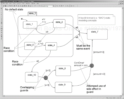
The first thing to notice about the statechart in the figure is that we didn't define the default state for the class. Is it state_0? State_10? Maybe state_7? We also didn't identify the default state in the lower and-state region of state_0.
Less obvious are the two race conditions specified in the and-states. The first is activated by the event e1. In one and-state, the action modifies the attribute x by augmenting it by one; the second multiplies it by three. The answer we get after the event is processed by the object depends on the order of execution of these actions but it is not possible, in principle, to determine what that order is. This is the classic definition of a race condition—a situation in which a computational result depends on an execution order, which is inherently unknowable. Not that using the same event in more than one and-state is inappropriate—in fact, it is a common way for synchronization of and-states when required. However, care must be taken that race conditions are avoided.
The second race condition is perhaps a bit more obvious. The e6 event causes two things to occur which are mutually exclusive. In the upper and-state region, it causes a transition to the state_1 nested state, while in the lower and-state region it leaves the composite state altogether. While this is obvious bad and not “computable,” there are more subtle versions of this. Suppose event evSub is a subclass of event e6 and it is this event that appears on the transition to state_10 in the figure. If an evSub6 occurs, then the state machine is still ill-formed because evSub is a kind of e6; therefore, when evSub6 occurs, all active transitions with e6 event triggers also fire.
At the bottom of the figure we see overlapping guard conditions. In this case, it is obvious that if x has the value 25, that both guards evaluate to TRUE. One could conceive of a tool that would find such overlapping conditions. Nevertheless, finding the general case of overlapping guards is NP-hard. Using simple guards will allow you to detect these conditions more easily.
On the right side of the figure we see a reasonable-looking transition: CoinDrop with an action to add the value of the coin to an attribute called “amount.” The problem lies in that the guards subsequent to that event signature use the amount attribute in the guard. What is probably meant is that the updated value of amount should be used in the guard execution; however, what is actually done is that guards are evaluated before any actions are taken. Therefore the value of amount examined is prior to adding in the value of the coin. There are a couple of common solutions to this. One is to use a choice point, although I personally don't recommend it for the reasons discussed previously. Another solution is to use more elaborate guard expressions such as [amount + coin>0], taking into account that it has not yet been augmented. Another solution is to add a state between the CoinDrop transition segment and the guards. This will force the completion of the action before the guards (now exiting the new state) are evaluated.
The last error on the diagram is that transitions with different events enter into a join. A join brings together transition segments from different and-states and must be triggered by a single event. Event responses are handled one at a time, in a run-to-completion fashion. Different events cannot be joined together.
A cardiac pacemaker is an excellent example of a system in which most objects use finite state machines. The problem statement below will be developed into a class model that will allow us to see how the various statechart features can be used in a real system.
This short problem statement can be represented by a simple class model, as in Figure 3-12. The pacemaker itself is shown as a structured class containing the three subsystems—Communications, PacingEngine, and Power. These subsystems contain the objects that collaborate to do meet the required functionality required of the subsystems.

The Communications subsystem, shown in Figure 3-13, contains instances of various classes that enable it to do its primary communications functionality. The ReedSwitch, CoilDriver, and Communications Manager and associated MessageQueues and Messages form the Communications subsystem. Note that the Communications Manager associates with two MessageQueues—one to hold messages waiting to be transmitted, and one to hold messages received via telemetry. The Communications Manager has an association with the PacingEngine subsystem to enable it to send the commands that change the pacing parameters, such as pulse width, pulse amplitude, pacing rate, and operational mode.

The PacingEngine subsystem internal structure is shown in Figure 3-14. This subsystem is straightforward. The Chamber Model defines the basic behavior for pacing a heart chamber, including associations to a PaceOutput object (providing an interface to the stimulation hardware) and a VoltageSensor object (providing an interface to the monitoring hardware). As an aside, the operations shown for the Pace Output and VoltageSensor classes are standard method calls, while the operation shown for the pacing classes (Chamber Model, Atrial Model, and Ventricular Model) are event receptors that show which events are received and processed by instances of the class. This is a bit more obvious on the state machines than on the class diagrams. Note also that the class diagram follows the common idiom of only showing the new operations (or events receptions) defined in the subclass and not those inherited from the superclass. These inherited operations are defined (in the superclass), but not shown in the subclass on the diagram.
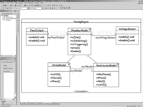
A statement about the generalization relationships in the pacing subsystem is in order. The Chamber Model class defines the basic behavioral model for pacing a cardiac chamber so it seems as though the Atrial Model and Ventricular Model ought to be instances of the Chamber Model class rather than different subclasses. If, in fact, the behavior of the two chambers differed only in their context, then a single class Chamber Model would be appropriate. However, we are going to specialize the Chamber Model class in how the two cardiac chambers define their behavior in AVI mode. This will allow us to define the basic behavior in the superclass and specialize it for the two subclasses.
Now that we have seen the structure of the Cardionada pacemaker, let's look at the behavioral model defined with the statecharts. The classes on the class diagram that have a state machine have a small icon in their upper righthand corner. Starting with the Communications Subsystem, we see that the reactive classes are the ReedSwitch, CoilDriver, and CommunicationsManager.
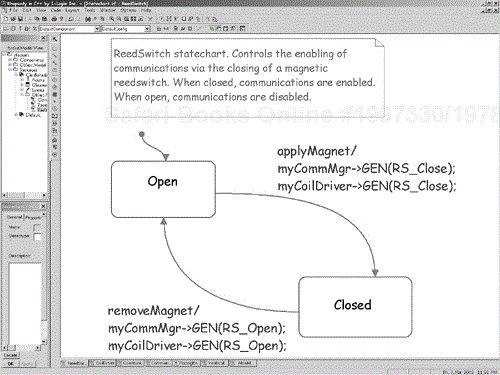
The ReedSwitch has simple on-off state behavior, as we see in Figure 3-15. It propagates events to other classes communication subsystem to enable and disable communications via the GEN() macro—specifically the ReedSwitch sends the RS_Close and RS_Open events to both the CoilDriver and CommunicationsGnome.
The CoilDriver class has more elaborate behavior (see Figure 3-16). The default initial state is Disabled. When the Reed Switch closes, it propagates an RS_Close event to the CoilDriver and the CoilDriver enters the Idle substate. The CoilDriver supports half-duplex operation—that is, it can either send or receive at any given time, but not both at the same time. In the Idle state, if an incoming pulse on the coil is detected, then it enters the ReceivingMsg state. The CoilDriver starts counting the pulses until it gets a timeout [shown as tm(BIT_TM)]. The number of pulses receives is then decoded into a bit value with the decode() action and then the next bit is retrieved. Once we receive all the bits in a byte, we add the byte into the message we are constructing and we wait for the next byte. At some point, we have received all the bytes [as indicated by the elapse of the timeout tm(MSG_TM)], and we now have a complete message. The message is then sent to the Communications Manager and the CoilDriver returns to the Idle state.
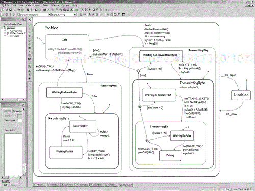
Transmission is begun when the CoilDriver receives a Send event with a message to send from the Communications Manager. The process to send is basically the reverse of the process to receive it. The first byte of the message is extracted, and then each bit, in turn, is extracted and is used to send the appropriate number of pulses out through the Coil.
The Communications Manager oversees the bidirectional communication process for the pacemaker. Figure 3-17 shows that the Communications Manager has four and-states: Receiving, CmdProcessing, MsgSending, and Queuing. These and-states proceed more or less independently except for synchronization points. The Receiving and-state validates messages that it receives from the CoilDriver and then either enqueues it from processing and responds to the programming device with an ACK message (if valid) or discards it and sends a NAK message if not. Validation is done via the isValid operation, which presumably checks the command ID, the message length, and a CRC.
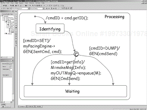
The cmdProcessing state is decomposed into a submachine, which is shown in Figure 3-17. The Dump command tells the pacemaker to start sending the queued messages, while the Set command sets the parameters or mode for the pacing engine.
The PacingEngine is where the pacing behavior occurs (see Figure 3-18). It changes mode only when commanded by the external programmer. When the Communication Manager receives a command to set the pacing mode, it validates the command and, if valid, processes it. The PacingEngine decides how to deal with these Set commands. For example, when a Set command that commands the pacemaker into VVI mode is received, the PacingEngine must send a ToIdle event to the Atrial Model instance and a ToInhibiting event to the Ventricular Model. To enter the AVI mode, the PacingEngine must send toAVI events to both the Atrial Model and Ventricular Model objects.

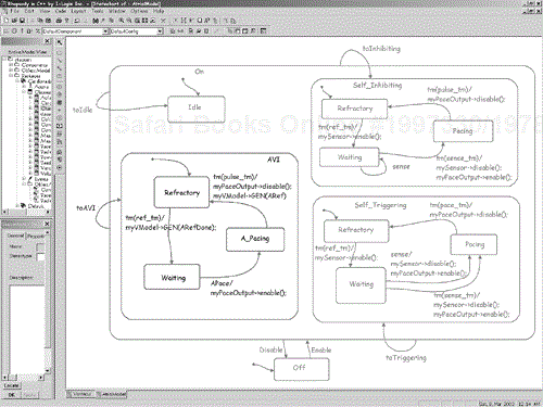
Most of the pacing behavior is defined in the Chamber Model statechart in Figure 3-19. If the Atrial Model is in the SelfInhibiting state and the Ventricular Model is in the Idle state, the pacemaker is said to be in AAI mode; if the Atrial Model is in the Idle State and the Ventricular model is in the Triggering mode, then the pacemaker is said to be in VVT mode. And if both objects are in the AVI state, then the pacemaker is in the AVI mode.

The next two figures (Figures 3-20 and 3-21) specialize the AVI state using the inherited state model rules given previously. By comparing the two specialized versions of the AVI state, you can see how the two objects communicate to coordinate their state machines. The Atrial Model and the Ventricular Model coordinate their activities by propagating events back and forth to ensure the behavior is correct in the AVI mode. The AVI mode is defined to be when the electrical activity in the ventricle is used to determine whether or not pacing should occur; the pacing is actually performed by stimulating the atrium of the heart. Further, if the ventricle beats on its own fast enough, then the pacing of the atrium should be inhibited.

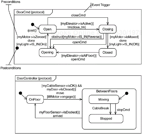
The state machines we dealt with in the previous section are called behavioral state machines because they specify how instances of a classifier respond to incoming events. There is another use of state machines, which is to define usage protocols for interfaces and ports; such state machines are called protocol state machines because they define the events and allowed sequences of events in usage protocols for classifiers. A protocol state machine defines which operations of a classifier may be called in which state and the pre- and postconditions for the execution of the operations.
As with behavioral state machines, protocol state machines must be “complete” in the sense that all the transitions that can result in the change of state and execution of operations must be captured. On the other hand, operations that do not affect the state machine are not represented on the protocol state machine. The purpose of the protocol state machine, once again, is to formalize the protocol of interaction (i.e., preconditions having to do with sequencing) for the classifier.
Protocol state machines differ from behavioral state machines in the following ways:
The key word “protocol” is used in the statechart.
Preconditions and postconditions are shown on the transitions as guards.
Actions are not permitted.
States may not have entry or exit actions or activities.
Figure 3-22 shows two examples of protocol state machines for the door management of an elevator.
Activity diagrams in UML 1.x were semantically equivalent to statecharts and shared a common metamodel. In UML 2.0, activity diagrams are given their own semantic basis independent from statecharts. In UML 2.0, there are multiple levels of activity diagrams: basic, intermediate, complete, and so on. The UML 2.0 activity diagrams are (mostly) compatible with the UML 1.x activity diagrams. In practice, the use of activity diagrams as “concurrent flowcharts” remains its most important usage in the real-time and embedded domains. Activity diagrams are usually used to specify the behaviors of operations and use cases and other classifiers. In usage, the difference between activity diagrams and statecharts is that statecharts are used when the classifier progresses primarily from state to state upon receipt of events of interest, whereas activity diagrams are used when the classifier progresses from state to state primarily when the actions done in the predecessor state have completed.

This is primarily because activity diagram semantics are based on the notion of token flow, from Petri nets, where a token contains an object, datum, or locus of control. The activity diagram is said to be in a state (or “node”) when that state contains a token. Tokens flow from node to node when the input edges connect to nodes that contain tokens. In the case of simple sequence flow, the transition between them fires when the predecessor node (activity) has completed its work. In the case of a join, there must be tokens in all the predecessor nodes before the subsequent node becomes active. Conversely, with a fork, when the incoming transition fires, a token is placed in all subsequent nodes.
In practice, statecharts are used to model the reactive behavior of classes and use cases, when they proceed via the reception of events. Activity charts are used to model control flow behavior of operations, activities on states (entry, exit, transition, and do activities) and use cases, and less often, classes. Note that entry, exit, and transition activities run according to run-to-completion semantics—that is, the object providing the context for these actions will not accept or process any event until those activities, and their nested actions have completed. Do activities are not run-to-completion and may accept events to terminate their execution. The common use of activity diagrams in the real-time and embedded domain is to show computational algorithms.
The model shown in Figure 3-23 shows how an activity diagram can model the behavior of an operation. In this case, the activity receives incoming data—SourceID—and processes the data into two concurrent flows, emanating from the fork pseudostate. The input data “appears” to the activity diagram on an input activity parameter node (a kind of object node, analogous to an input pin on an action). The computation result appears on an output activity parameter node (analogous to an output pin on an action). One of the concurrent flows initializes the sensor and acquires the data. The other readies the filter. Once this is done, the join then brings together the concurrent flows and filters the data and returns it. Remember that the output flow from the join fires only when control tokens appear on all of its predecessor nodes. This is just a fancy way of saying that it fires only when both threads feeding into it have completed their processing.
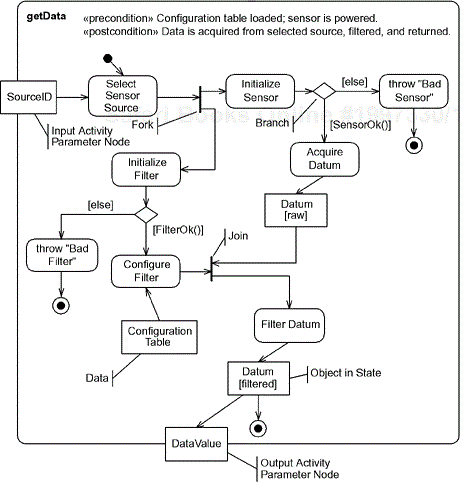
Note the use of a “class box” to represent data, whether it is a class or just an ADT (abstract data type). The Datum is shown using the “object in state” notation (the name of the current state shown inside square brackets), making the state of the Datum visible as that datum is processed in the activity. Note also the use of preconditions and postconditions to clarify the processing requirements of the activity.
There are some additional notations available for activity diagrams. In Figure 3-24 we see special symbols that can be shown for event reception. In the example, a Proximity Alert might be created when a beam of light is broken (such as when a human arm crosses its path). In the activity diagram, this event causes the behavior in the interruptible segment (indicated with the dashed rounded rectangle) to abort, and the control path to the Emergency Stop activity is taken. The use of explicit “interrupting edges” is an important departure from UML 1.x activity diagrams; in its earlier incarnation, UML allowed a flow on an activity diagram to be triggered by an event.

Swim lanes define partitions in the activity diagram that can be bound to objects or object roles. This provides activity diagrams with the ability to represent interactions of objects during the execution of the activity flow. Swim lanes enable the depiction of interactions of multiple objects during the execution of an algorithm. In addition, activity states themselves can also be decomposed on the same or on different diagrams. This is crucial for the scalability of the notation to model complex algorithms. The official notation used to indicate that an activity is decomposed on a separate diagram is an inverted three-pronged fork.
In the previous section, we saw how the behavior of individual classifiers, such as classes and use cases, can be modeled using statecharts and their close cousins, activity charts. In this section, we will see how the UML models the collaborative behavior of multiple entities working together.[11] Collective behavior, or interactions, concerns itself with the (partially) sequenced exchange of messages (which may be events, operation calls, or instance creation/destruction actions) among a possible large set of interacting objects.
There are three primary diagrammatic forms in the UML for depicting interaction scenarios—communication diagrams,[12] sequence diagrams, and timing diagrams. Communication diagrams are basically object diagrams with messages shown, each with a sequence number. Because communication diagrams are relatively little used as compared with their cousin, the sequence diagram, they won't be discussed here. Timing diagrams emphasize the changes in value or state over time for either single or multiple classifiers roles. Timing diagrams are discussed in Section 3.5.2.
Figure 3-25 shows the basic elements of a sequence diagram. The five-sided box at the upper lefthand corner names the sequence diagram. In general, a sequence diagram contains one or more interaction fragments, each of which is enclosed in a frame and one or more operators. As previously mentioned, sequence diagrams are more commonly used than communication diagrams even though they show basically the same information. The reason is that sequence diagrams emphasize sequence over structure, so it is very easy to find the “next” message—it is the message following the current one in the diagram. Time goes down the page, but not normally linearly; that is, further down implies later in time, but 2 cm at one place in the diagram does not imply the same amount of time as 2 cm somewhere else on the diagram. Further, because messages on sequence diagrams are only partially ordered (a topic discussed shortly), in many cases the relative timing between messages is not specified. Since timing diagrams are shown against a common clock (depicted with the time ruler on the diagram), timing diagrams messages are fully ordered. When time, rather than sequence, is the primary focus, I recommend that timing diagrams be used instead.
The vertical lines, called lifelines, represent the roles (i.e., parts of a composite class or a object roles in a collaboration) the instances play during a scenario. These roles may be parts of a collaboration and/or internal parts of a structured class, component, or subsystem. Objects roles can send and receive messages during the execution of a scenario. Messages are represented by the arrowed lines going from one lifeline to another. These messages can be synchronous or asynchronous, calls or signals.
The frame enclosing the diagram encapsulates an interaction fragment. Each interaction fragment has at least one operator, held in the five-sided box at the upper left corner of the interaction fragment. Section 3.5.1.2 details the standard operators available.
The sequence diagram in the figure has other elements that could be found in the sequence diagrams in UML 1.x: constraints, states, messages, and so on. One of the most important differences between UML 2.0 sequence diagrams and UML 1.x sequence diagrams is the ability to decompose interaction fragments into nested interaction fragments. Figure 3-25 has three interaction fragments. The sd operator names the primary interaction fragment, but there are also two nested interaction fragments. The ref operator identifies the name of the sequence diagram that is being referenced, but not shown in the current diagram. Each of these features will be discussed in more detail shortly.
There are more annotations available, as shown in Figure 3-26. Messages can be either lost or found. Lost messages are pretty obvious—a message is sent, but due to some error or failure, it fails to arrive at its destination. The notation for that is to have the message terminate in a circle. Conversely, a found message arrives from an unknown or unspecified source; this is shown with a message starting from a circle.
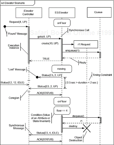
As with UML 1.x, activation of an instance can be shown, although the UML 2.0 specification refers to this as an execution instance. This is shown with the shaded rectangle placed onto an instance line to show that the instance is actively executing behavior in response to receiving a message. This annotation is really only useful for completely synchronous calls among instances, and I personally tend not to use the notation for that reason.
The kind of message may be shown as well. Open arrowheads denote asynchronous messages, while a filled arrowhead indicates a synchronous call. The open arrowhead with a dashed line is optionally used with the call message to show a reply. Replies may also be shown as a return value on the original message, as in
goto(4, UP): TRUE;
which indicates that TRUE is returned.
A large X at the terminal end of a lifeline indicates that the instance has been destroyed. In the figure, we see the Elevator lifeline destroys the request lifeline when the request has been fulfilled.
We've already seen that states on the lifelines show the state of the instance playing the role of the lifeline in the interaction. We can use any testable condition, such as the value of an attribute. In the figure, we show how the value of the floor attribute can be shown on the Elevator lifeline.
The last new thing shown in the figure is the coregion, an area on the lifeline between square brackets. In a coregion, we do not care about, and do not specify, the order of the messages. This violates the normal partial ordering rules discussed in the next section. A more general way of showing coregions is to use the par operator, as discussed in Section 3.5.1.2.2.
A note on ordering in interactions is appropriate here. Even experienced UML users are often surprised to learn that interactions are only partially ordered. They expect that if a message begins or terminates below another then it comes after the other in absolute time. This is not quite true. Sequence diagrams support concurrent semantics, which means that the relative ordering of some messages is not specified.
For example, does message m0 precede m1 in Figure 3-27? The answer is, we don't know, because they begin and end on different lifelines. A sequence diagram shows a trace of message exchange among the lifelines of interest. Sequence diagrams assume concurrency may exist between the lifelines. What concurrency means is that within a concurrent thread, operations are fully ordered, but between concurrent elements, nothing can be said about the relative ordering of operations, except at points of synchronization between the concurrent elements. We can think of each message as being associated with two events—one event that sends the message and one event that receives the message, as shown with the constraints for m0.send() and m0.receive() in the figure. The two kinds of sequences that are fully ordered are the events that occur on a single lifeline and the receive() events that follow the corresponding send() events.

This means that in the figure, m0.send() precedes m0.receive(); m1.send() precedes m1.receive() and so on. Further, the events on the Object1 lifeline are fully ordered; m0.receive() precedes m3.send(), which precedes m5.receive(). However, you can't tell from the sequence diagram whether m0.send or even m0.receive() follows m1.send() or m1.receive().
In the sequence diagram shown in Figure 3-27 the following orders can be determined:
m0.send()->m0.receive()
m1.send()->m1.receive()
m2.send()->m2.receive()
m3.send()->m3.receive()
m4.send()->m4.receive()
m5.send()->m5.receive()
m1.receive->m2.receive()->m3.receive()->m4.send()->m5.send()
m0.receive()->m3.receive()->m5.receive()
But we cannot assume that even messages that are sent in a particular sequence are received in the same sequence, if they terminate on different lifelines. For example, it is clear that m0.send() precedes m2.send() because they initiate from the same lifeline. However, they terminate on different lifelines so one cannot assume that m2.receive() occurs after m1.receive(). If m2.receive() arrives prior to m0.receive(), this is called message overtaking. How can this occur? Imagine that Object 0 and Object 1 both reside on a computer in Mission Control, while Object 2 resides on a probe orbiting Europa. Obviously, message transmission time on the same computer requires orders of magnitude less time that transmission across hundreds of light minutes. Even in more mundane applications, the priorities of different threads can mean that messages sent earlier may still be received later. The problem is further exacerbated with distribution of objects across multiple processors and physical locations.
We have seen that the interaction fragments on sequence diagrams have operators. So far, we've only seen the sd (interaction fragment name) and ref (interaction fragment reference) operators but there are quite a number. The predefined operators are shown in Table 3-2.
Table 3-2. Interaction Operators
Operator | Description |
|---|---|
sd | Names an interaction fragment. |
ref | References an interaction fragment, which appears in a different diagram. |
alt | Provides alternatives, only one of which will be taken. The branches are evaluated on the basis of guards, similar to statecharts. An else guard is provided that evaluates to TRUE if and only if all other branch alternatives evaluate to FALSE. |
opt | Defines an optional interaction segment; that is, one that may or may not occur depending on the runtime evaluation of some guard. |
break | Break is a shorthand for an alt operator where one operand is given and the other is the rest of the enclosing interaction fragment. A sequence diagram analogue to the C++ statement. |
loop | Specifies that an interaction fragment shall be repeated some number of times. |
seq | Weak sequencing (default). Specifies the normal weak sequencing rules are in force in the fragment. |
strict | Specifies that the messages in the interaction fragment are fully ordered—that is, only a single execution trace is consistent with the fragment. |
neg | Specifies a negative, or “not” condition. Useful for capturing negative requirements. |
par | Defines parallel or concurrent regions in an interaction fragment. This is similar to alt in that subfragments are identified, but differs in that all such subfragments execute rather than just a single one. |
criticalRegion | Identifies that the interaction fragment must be treated as atomic and cannot be interleaved with other event occurrences. It is useful in combination with the par operator. |
ignore/consider | The ignore operator specifies that some message types are not shown within the interaction fragment, but can be ignored for the purpose of the diagram. The consider operator specifies which messages should be considered in the fragment. |
assert | Specifies that the interaction fragment represents an assertion. |
The most important of the operators are discussed in more detail in the text that follows.
There are several operators devoted to branching: alt, break, opt, and loop. All (except break) are shown in Figure 3-28. For those readers who remember the (admittedly pathetic) branching capability of UML 1.x sequence diagrams, the alt operator for interaction fragments will be a very welcome addition to the UML. With the alt operator, the fragment (called a compound fragment in this case) is broken up into multiple sections, separated by an operand separator—a dashed line crossing the width of the fragment. Guards control which of the alternative branches will be taken. Remember, this is branching, rather than concurrency, so that at most only a single operand fragment will execute. The fragment being operated on by the alt operator in the figure has three operands, each with a separate guard. The [else] guard is TRUE if and only if the other guards are all FALSE. If all the guards of an alt operator are FALSE, then none of the operands will execute; if multiple guards are true, then one of the operands guarded by a true guard will execute but you cannot predict which one it will be (normally an undesirable situation).
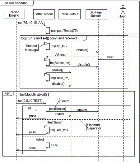
The opt operator is like an alt with a single operand—it designates its fragment as being optional.
Loops are shown with the loop operator. The loop operator may specify the minimum number of iterations as well as the maximum number of iterations inside square brackets. If no numbers are specified, then [0, *] is assumed, where the asterisk (*) is indeterminate. If only the first number is given, then the fragment will iterate a fixed number of times. By adding a constraint, we can limit the number of times the fragment will execute. In the figure, we indicate that the specified fragment will iterate until a set() command is received by the pacing engine.
Note also the special notation used for a timeout message. While not officially part of the standard, it is often useful to indicate timeouts as special. They are shown as a “message to self” initiating from a small square. A cancelled timeout (not shown) has the same notation, except that the message arrow is dashed.
If alternatives were painful to show in UML 1.x sequence diagrams, parallel regions were well nigh impossible. UML 2.0, however, makes specifying parallel regions on sequence diagrams easy. The par operator indicates two or more parallel regions, but otherwise looks much like the alt operator. In Figure 3-29, two parallel regions are shown for the microwave oven. The consider operator (discussed in the next section) indicates that these messages have special meaning and should not be ignored should they occur. Inside each of parallel regions is a loop; the first specifies an unlimited number of iterations but is constrained to terminate when the attribute timeToCook reaches zero. The second doesn't specify a terminating condition. The par operator is a more general (and useful) form of the coregion operator shown in Figure 3-26.

Also notice the critical region in one of the parallel regions. This has the same meaning as a critical section in normal concurrency programming—that is, traces of execution of this fragment cannot be interleaved with other possible concurrent fragments. Normally, a critical Region fragment is nested within one of the parallel regions as it is in the figure.
The assert operator indicates that this must be true for the trace to be considered valid. This essentially adds causality to sequence diagrams and allows them to be used to specify test vectors. The assert operator is discussed more in the next section.
UML 1.x sequence diagrams really don't have any notion of causality—they are merely traces of what happened or what could happen during an interaction. They don't specify what must happen. David Harel and Werner Damm [5] have done some work on adding the notions of causality to sequence diagrams. These notions have been added, although in a somewhat different form, to the UML 2.0 sequence diagrams with the consider, ignore, and assert operators.
The ignore operator lists messages, as parameters, that are outside of the causal stream and may be ignored. For example, consider the ignore operator in Figure 3-30. It says that while the Door is opening, presses to the open button (resulting an OpenCmd) are ignored, which is behavior you would expect.
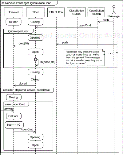
Also note that the sd and ignore operators are combined in the primary fragment shown in the diagram. This indicates that pressing the CloseButton has no effect on the scenario.[13]
In the lower part of the figure, the consider operation is used. Consider is the opposite of ignore. It considers the specified messages (in this case, stopCmd, arrived, and cableBreak) are the important ones, and all other messages may be ignored.
Finally, the assert operator is used inside the consider fragment. The proper interpretation of this fragment is that an openCmd must follow the arrived message.
Probably the most significant improvement in sequence diagrams with UML 2.0 is the ability to decompose the diagram into subparts. UML has always had the ability to do this with class diagrams and statecharts, but sequence diagrams lacked a standard way to do such decomposition. This feature is crucial for effective large-scale systems development because such interactions become complex in at least two ways.
First, many more interacting elements become added to interactions as designs evolve and are elaborated. In class diagrams, this is handled by using structured classes and composition relationships and by showing only the internal structure of the larger-scale objects. The second way that sequence diagrams become more complex is that more messages, more alternatives, and more variants are added.
The addition of operators, such as alt and par, help this problem tremendously, but there is still a need to move all the details of an interaction and show it on a separate diagram. This might be done to manage a complex scenario as well as when the same sequence may be referenced from more than one interaction fragment. UML 2.0 sequence diagrams allow this kind of decomposition in two ways: referencing interaction fragments and decomposing lifelines.
Figure 3-31 illustrates both means of decomposing sequence diagrams. The lifeline Communications is decomposed in the interaction fragment called Check Device. The decomposed interaction is shown in Figure 3-32. The decomposed lifeline includes more lifelines than the first. This is one of the advantages of such decomposition—it allows us to manage the burgeoning complexity of our sequence diagrams as more and more lifelines are added. In addition, the Check Device fragment itself includes interaction occurrences that reference interaction fragments shown elsewhere. This allows us to hide the details of the “bit banging” done during the actual transmission and reception of the bits with the CoilDriver. Lastly, we see that message enter and leave this interaction fragment. Each point on the frame where a message enters or leaves is called a gate. To be well formed, the referenced fragment must a corresponding gate for every gate that appears in the interaction occurrence, and the message type and parameters must be consistent as well.
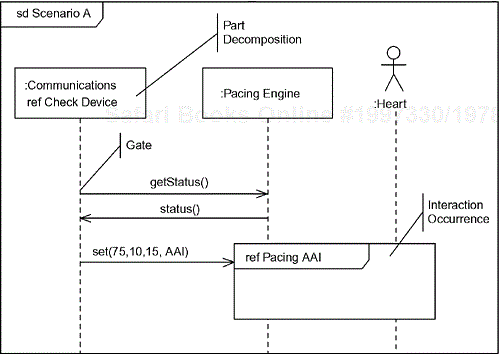

The other kind of decomposition is to have an interaction occurrence that references a separately defined interaction fragment. In Figure 3-31, this is the nested fragment called Pacing AAI. The internal structure of that interaction appears in Figure 3-33. Just as in the previous decomposition, this fragment details the internal structure of the interaction and may add additional lifelines as necessary.

Clearly, these means for decomposing sequence diagrams allow us to construct and understand complex interactions far better than the sequence diagrams from UML 1.x.
Electrical engineers have used timing diagrams for a long time in the design of electronic state machines. A timing diagram is a simple representation with time along the horizontal axis and object state or attribute value along the vertical axis. Of course, electrical engineers usually only concern themselves with a small number of states for an individual circuit node, such as low, high, or high impedance.[14] Software engineers can use timing diagrams just as easily on much more elaborate state machines or many-valued attributes to show how the values change over time.
Timing diagrams are similar to sequence diagrams in that they show traces, or scenarios, of collaborations. Many different traces are possible with the same collaboration. This is different than statecharts in that statecharts specify all of the reactive behavior of the classifier it is specifying.
Timing diagrams depict state (or value) as a horizontal band across the diagram. When the system is in that state, a line is drawn in that band for the duration of time the system is in the state. The time axis is linear, although special notations are sometimes used to indicate long uninteresting periods of time. The simple form of a state timing diagram is shown in Figure 3-34.

This timing diagram shows a particular path through the Atrial Model state machine. It begins in the Idle state and remains there until it receives a command to enter begin pacing (To Inhibiting). At this point, it jumps to the sensing state. The vertical line segments connecting states show that the time used for the transition is (approximately) zero relative to the scale of the timing diagram. Later, an atrial sense is detected (as shown by the transition annotation on the diagram) and the Atrial Model returns to the sensing state. Sometime later, the sense timeout occurs and the Atrial Model enters the pacing state. In this state, the engine is actively putting an electrical charge through the heart muscle. When the pacing pulse width is complete, the object transitions to the refractory state. Once this times out, the system reenters the sensing state. The timing diagram view is preferred to the sequence diagram view when time is of critical importance, as opposed to sequence.
We see constraints and other annotations on the timing diagram. Constraints are useful to help specify the timing requirements. For example, the timing for the transition from the refractory state in Figure 3-34 might be 19.6 ms, in this particular scenario, but this is within the required time window of 20 +/- 0.5 ms.
In this simple form, only a single object (or system) is represented. It is possible to show multiple objects on the same diagram. Separating these objects with operand separator lines clearly delineates the different (and possibly concurrent) objects. Propagated transitions can be marked with directed lines showing event dependency. Figure 3-35 shows just such a diagram depicting a scenario of collaboration among three objects involved in the transmission of telemetry. We see the collaboration unfold as they exchange messages. When it is inconvenient to draw the message from one lifeline directly to another, labels can be used, as with the case of the send(value) message.
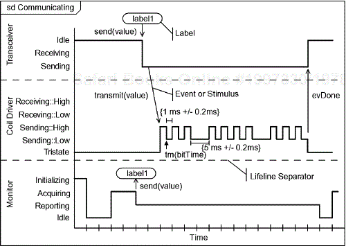
Timing diagrams are very good at showing precise timing behavior and are often used to closely analyze the timing of periodic and aperiodic tasks. When used in this way, some common elements are shown in Table 3-3.
Table 3-3. Commonly Shown Timing Information
Period | The time between initiations for the same state. |
Deadline | The time by which the state must be exited and a new state entered. |
Initiation time | The time required to completely enter the state (i.e., execute state entry actions). |
Execute time | The time required to execute the entry and exit actions and the required activities of the state. |
Dwell time | The time the object remains in the state after the execute time before the state is exited. Includes time for exit actions. |
Slack time | The time between the end of actions and activities and the deadline. |
Transition time | The time required for the transition into the state to complete. This includes the time necessary to execute the transition actions. |
Jitter | Variations in the start time for a periodic transition or event. |
When there are many tasks to be shown on a single diagram, a common simplified form of the timing diagram shows only which task is executing at any point in time (see Figure 3-36).[15] If desired, more details of the task state can be shown with pattern shading, as in Figure 3-37. Although timing diagrams show no information beyond that available in annotated sequence diagrams, the absolute timing of events and state changes and the relative timing among objects is much clearer and more obvious than on sequence diagrams, even when explicit timing constraints are added.
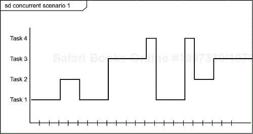

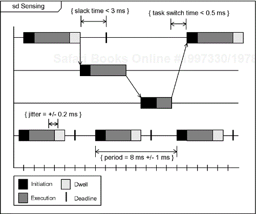
Lastly, timing diagrams can be used to show the values of attributes. Commonly, timing diagrams are used to show the changes in values of discrete enumerable attribute values, but they can also be used for continuous values, as shown in Figure 3-38. The “preferred” form, shown at the bottom of the figure, is appropriate when a value is changed in respond to a change event at some specific point in time. The attribute holds the value until the message is received and the value is (discontinuously) modified. For systems or continuous modeling, this format may not be very helpful, so a second notation is recommended in these cases, shown in the upper part of the figure.[16]
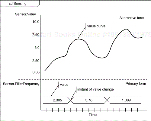
We have seen in this chapter the richness of the UML's behavioral modeling capabilities. Actions provide the most primitive units of behavior. Activities bind actions together into sequences connected via logical operators, such as branching and forking, as well as providing execution connections for them. Statecharts and activity diagrams allow us to depict the set of allowable sequences for the execution of these actions. Protocol state machines allow us to define the protocols of interaction among various classifiers. On the other hand, interactions cannot be conveniently represented by a state machine, since a state machine is bound to an individual classifier. For interactions, we model traces of event or message exchange among the instance roles participating in the interaction. Sequence diagrams are the most common means to capture such interactions. The UML 2.0 has introduced ways to manage the complexity of interactions with interaction fragments, operators, and the ability to decompose interactions into smaller interaction fragments. For those concerned especially with time, timing diagrams provide an expressive means to detail change in value or state of classifiers and attributes.
In the next chapter, we focus on the specification of time and modeling of timing constraints. There is an adopted standard for this, the “UML Profile for Schedulability, Performance, and Time,” which captures the most common ways in which this was done in the past and abstracts them, then codifies them into a standard. While you are certainly free to use your own tags and constraints for capturing timing and performance requirements, the existence of a standard will facilitate the exchange of models among different tools.
[1] PID, proportional integral-differential, is a common type of control theoretic system that uses feedback, integration, and differentiation to smoothly control continuous systems.
[2] As of this writing, work is under way on the “UML for Systems Engineering” specification. This work defines a means for modeling truly continuous behavior via extensions to activity diagrams. This UML extension is expected to be adopted by the OMG as a separate specification in late 2004 or 2005.
[3] Although it does define the semantics for an action language, the UML does not define a syntax, a necessary aspect of any language.
[4] Entry, exit, and transition activities have run-to-completion (i.e., noninterruptible) semantics, while do activities are interruptible.
[5] A highly recommended state to be in!
[6] Exercise left to the reader.
[7] IN( ) is another common form for this operator.
[8] This pseudostate was removed in the 1.3 revision of the UML, after it was noted to be just a kind of the junction pseudostate. However, since it is still widely used in tools, I have continued to use it here.
[9] In the general case, this is very difficult to automatically check for, because the guards may invoke operations that have nested operations. Therefore, modeling tools don't usually check for this kind of error.
[11] As noted in the previous section, activity diagrams with swim lanes can be used to specify interactions; sequence diagrams are used to show specific scenarios, which are, in some sense, instances of those specifications. However, the elaborations of sequence diagrams in UML 2.0 make that distinction fuzzier.
[12] In UML 1.x these were known as collaboration diagrams.
[13] You always suspected as much didn't you?
[14] In some cases, electrical engineers will be concerned with a somewhat larger set of states, such as strongly but consistently driven (transistor driver) high and low, strongly and inconsistently driven (conflict), weakly driven (resistively driven) high and low, floating and undriven (high impedance, all outputs tri-stated) high, low and in the transition region, unknown transistor driven, unknown resistively driven, transitioning monotonically, transitioning with oscillation, and so on. But usually not ;-)
[16] This is, likewise, an extension to the current adopted specification. It is being used in the work being done for the “UML for Systems Engineering” specification—an effort with which the author collaborates.