
Room Combinations and Operational Considerations
Juxtaposition of different working areas. Choice of appropriate acoustic spaces. Door and window isolation. Multiple glazing considerations. Modal control of small rooms. Special recording techniques.
As has no doubt become clear by now, no one room can perform all the functions which may be required for the recording of the whole range of probable musical performances. The large, variable room is perhaps the best option if money and space allow such a room to be built, but even the best such room can never mimic the performance of a good, small live room, or a good stone room: at least not without absurd complexity of structure and mechanisms. We should now, therefore, consider how we could put together the pieces so far discussed in order to make a viable, practical, and effectively flexible studio package.
8.1 Options and Influences
Let us imagine that we were presented with a building in which to construct a studio, and that we had the luxury of 500 m2 of floor space and 6 m of ceiling height. This would give us enough space to construct a large, variable, general recording area, plus a stone room, a moderately live room, a vocal room and a dead room. However, the layout of such rooms is full of compromise, forced upon us by many conflicting priorities. Ideally, everybody needs to be able to see the control room, but also, everybody needs to be able to see each other. At the same time, the general influence of the positioning of the smaller rooms should not detract from the optimum shape of the main studio area. This may all seem rather obvious, yet it is surprising just how many studios are built without the most basic of these requirements being given their due consideration; this even includes some studios which have ostensibly been professionally designed.
One practical option for our 500 m2 studio could be that which is shown in Figure 8.1. This first appeared in the book Recording Spaces1 in 1998, which directly led to the construction of the two studios shown in Figures 6.13 and 8.2, though on slightly more modest scales than the 500 m2 proposed. They were built in 320 m2 and 220 m2 respectively, and as can be seen they are practical realisations of many of the points discussed in previous chapters.

Figure 8.1 Layout of hypothetical 500 m2 studio

Figure 8.2 The main room in Tio Pete studios, Urduliz, Bilbao, Spain, loosely based on the drawing of Figure 8.1 (1999)
As a contrast, Figure 8.3 shows an actual situation that was in a 90% completed form before it was realised that it was not going to perform as expected, and over €60,000 had already been spent on the rooms. The designs had been done by a theoretical acoustician with some theatrical acoustics experience, but who was not a specialised studio designer, and all the rooms had been designed around the use of large semi-cylindrical diffusers, Helmholtz resonators and absorbent/diffusive tiles made from gypsum and mineral wool. All the rooms had been designed to classic RT60 figures, and somewhat surprisingly all had been aimed at a somewhat similarly neutral acoustic performance, except for the slightly longer RT in the larger room. The windows and doors had been situated in accordance with structural simplicity rather than acoustical, operational, or musicians’ needs. Perhaps this fact, more than any other, made the task of modifying the studio all but impossible.
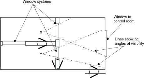
Figure 8.3 A studio designed by a general acoustician. Musicians in positions X and Y (the natural positions for good visibility into the larger recording room and control room) are unable to see each other. Insufficient thought had been given to practicalities
It was ultimately the owners themselves who suggested a total re-build. What was so distressing was that if it had been built with the internal walls, doors, and windows, such as shown in Figure 8.4, it would have been much more rescuable. What is more, it would have cost no more to build the Figure 8.4 version than to build what had actually been built. It seems however that the only design considerations had been separation and acoustic decay-time control. The designer had failed, almost totally, to consider the needs of the musicians or the recording engineers. It had been built for a partly grant-funded arts organisation, and the bureaucracy had dominated events.

Figure 8.4 Layout that could have been workable, using similar space and materials as Figure 8.3. Note also the improved angles of visual contact between the rooms
The sad thing about the above situation is that with a little more forethought and experience, the use of the layout of Figure 8.4 would have allowed the construction of an excellent live room in section ‘Y’, a good vocal room in section ‘X’ and the shape of the larger room would have allowed much better acoustic control without having to resort to the ‘battleship’ methods which lost so much usable space in the original layout. Unfortunately, such things are all too common in community and educational establishments, where specifications and tenders are dealt with by administrators and not by artistes or engineers. Even in many universities!
8.1.1 Demands from Control Rooms
Even ‘external’ things, such as the control rooms will make their demands on the design of the studio rooms. As will be discussed in later chapters on control room and monitoring design, whether you have a wonderful set of studio acoustics or not, recording is like driving blind if the control room monitoring and acoustics are not sufficiently sonically neutral and free from idiosyncrasies of their own. To make the best of what the studio acoustics, microphones, and musicians have to offer, it is imperative that the control room should not be compromised. The most likely compromise in this area is to visibility, which is indeed very important, but there are optimal locations in control rooms for loudspeaker positions, and it is generally unwise to push the monitor loudspeakers into high locations, where the ear perceives things very differently than from a horizontal direction, all for the ‘luxury’ of an enormous front window.
Large windows are problems in themselves. The bigger they get, the more they tend to allow sound through, or to resonate in unwanted frequency bands. That is, unless they are of a very great weight, in which case they may need to be custom-made by a specialist glass factory, the cost of which can be alarming. Two-way closed-circuit television (CCTV) is one possible solution for visibility between the control rooms and any out of the way places. With the older, cathode-ray tube (CRT) based systems, there is often the problem of the 10 or 15 kHz time-base whistles from the TV monitors. Some people find these to be extremely irritating, but perhaps more dangerously from a recording point of view, many people, particularly over the age of 35 or 40 years, cannot hear them at all. In such cases, if the whistles do pick up on the recording microphones, and especially if any top boost is applied on the console, then they can pass unnoticed on to the master recording, only to subsequently irritate the purchasers of the final product. More recently, the advent of cameras and monitors which are not based on CRT technology has made this problem less common, and so has opened up more possibilities for the application of CCTV.
Access to and from the control room is another important point to consider, but the position of doors may be dependent upon control room design philosophies. In situations where the rear wall of a control room is sacrosanct, and solely to be used for absorber systems, the need for front or side entrances is fixed. The rear wall is perhaps the most critical surface, as it takes the full impact of the incident wave from the monitor system, and anything coming back from that wall will be likely to colour the perception in the room. The low frequency absorber or diffuser surfaces need to be as large as possible, so penetrating them with doors is generally undesirable. Sliding glass doors in the centre of the front wall is another option, but such relatively lightweight structures so close to the monitors can be problematical. Unless the glass is very heavy, so much so that perhaps opening and closing the doors becomes a difficult exercise, any LF resonance which exists in the door system will not only cause a perceivable resonant overhang, but will also absorb some of the impact from the bass end of the monitor system.
If the control room is sufficiently wide, then a heavy window can be placed centrally, between the monitors, and heavy doors of composite nature can be located beyond the outer sides of the monitors. These can provide access to the studio rooms, and to the reception areas or access corridors if necessary. If side-doors must be provided to a control room, it is often wise for them to be as far to the back of the room as possible, to avoid disturbing the absorption system on either side of the mixing position. However, if they must be at the sides, they can often be angled so as to tend to reflect any sound which strikes them into the rear absorber or diffuser. Every situation is different, with its own set of specific demands. If the control room is to be of a type such as the Live-End, Dead-End, with a live rear half to the room, then the compromises could be somewhat different. The whole design must be integrated if the best results are to be turned from expectation into reality.
In Figure 8.1, the control room is flanked on one side by an access corridor, and on the other side by a machine room and a vocal room. If any one of the studio rooms needs to be alongside the control room, it is better to be one of the most acoustically dead of the rooms, because the SPL which can develop in the live rooms can present much greater sound isolation problems if they are adjacent to the control room. Also, usually, the dead rooms will be used for much of the vocal overdubbing work. This process can consume a great deal of time, so a location close to the control room is convenient and expeditious. The arrangement shown allows access and visibility directly from the vocal room to and from the control room and the studio, so whether doing live vocals or overdubs the vocalist will not feel too isolated.
Already, having discussed so little about the studio layout itself, we have been diverted by considerations from some seemingly secondary sources, but their pull is great, and any studio designed without due consideration of the widest spheres of influence will likely fail to achieve its full potential. Different designers will have their own very special priorities which they will try to avoid compromising, and each of these points is likely to be based not only on knowledge of facts but also on insight gained through years of practical experience. This is largely what separates studio designers from other acousticians. Even amongst studio designers their experiences will have been different, and the individual tastes of the designer will be different, so this will lead to some very different designs. This is actually quite fortunate, as without variety things would be a little dull. There is therefore no ‘bible’ which governs this subject absolutely.
8.2.1 Priorities and Practice
Figure 8.1 shows a very attractive layout, but such a flexible option is expensive to build. The prospective owners of such studios need to be sure of their market. Studios are usually built on budgets that must be earned back over a matter of a few years, and so must be constructed with the appropriate economic considerations in mind. The studio shown in Figure 6.13 was built in 2000 at a cost of about €800,000 for the specially constructed building and all the internal acoustic work and decoration. When we cut our budgets we usually also cut our options, so a designer must consider carefully the most likely uses to which a studio will most frequently be put. If it is proposed to record many voices, or chamber orchestras, then obviously a stone room and a dead room would not be an appropriate choice of combination. There are a few studios which earn their livings from a single live room, but they tend to cater for niche markets. It is likely that if any of them were to build a second studio room, then it would either be a neutral room, a dead room, or a room with some degree of variability, but not another live room.
So let us now discuss some of the important points which went into the design of a small pair of studios which were squeezed into a space of only 100 m2. They were designed for a wide range of music recording, plus dialogue replacement for cartoons and short films. The discussion can be used to highlight many constructional details and pertinent specifications. In the design shown in Figure 8.5, Control Room One was the main control room for music recording. Previous experience had led the owner to believe that they needed a good live room and a vocal room which would not colour the sound. The second control room was not intended to be used for serious mixing purposes, but it should be neutral enough to make a good editing room and to be able to function as a control room for overdubs or dialogue replacement. In Figure 8.5, it can be seen that Control Room Two has an adjoining Studio Two, which is only large enough for one musician and instrument at a time, or perhaps a trio of backing vocalists, but this room also had to serve as a third recording space for Control Room One. The problem was that Studio Two would best serve Control Room Two if it were a room which was as dead as the ones shown in Figure 5.19, but Control Room One already had such a room adjacent to it, so doubling up on such rooms would seem to serve little purpose. It was eventually decided to make Studio Two a bi-directional room, which could serve as a relatively dead room when being used with Control Room Two, but would have more life when used with Studio One.
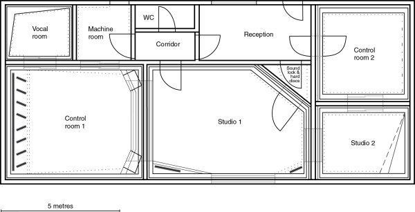
Figure 8.5 General layout of a small studio complex – ‘Tcha Tcha Tcha’ Lisbon, Portugal, (1996)
It was presumed that when being used as an extension to Studio One, the musicians would be facing Control Room One, and when working with Control Room Two, the musicians could face the opposite direction without losing visual contact with Control Room Two. Figure 8.6 shows the idea in more detail. The main problem with this option was how to make a small room with the required brightness, but without the boxiness which usually accompanies such designs.
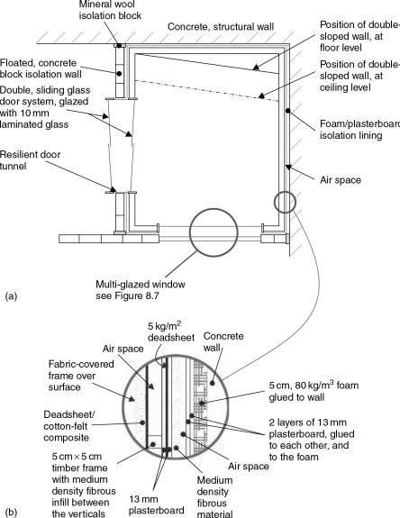
Figure 8.6 Small room using the double-sloped ‘Geddes’ wall principle. (a) Plan view, (b) detail of wall structure
8.3 Isolation Considerations: Doors and Windows
Isolation was a great priority, not only because the two studios had to be able to work separately, but also because the poor reputation from bad separation between the previous studios which had occupied the building (and which had partly led to the need to re-build) had to be ended once and for all. The wall between Studios One and Two was a massive, sand-filled concrete block construction, floated away from the structural walls, floor and ceiling with high-density mineral wool. Each side of the wall was treated with 6 cm of 80 kg/m3 open cell polyurethane foam, then two sheets of plasterboard, all layers bonded only with contact adhesive. All three studio rooms and both control rooms were separately floated on 120 kg/m3 polyurethane foam (Arkobel) but Studio Two had a second floated floor, of different density and thickness to the other floated floors. This was to avoid any common resonances in similar construction methods which could have reduced the isolation at any common resonant frequencies. The shell treatment of Studio Two was essentially the same as that described in Chapter 5. The room began as a dead room, but with the additional life of the double glass door system to the control room, plus a quadruple glazed window to Studio One. However, before looking in detail at the system of livening Studio Two, perhaps we should first look here at the door and window systems.
8.3.1 Sliding Doors
The two door systems were each made out of two panels, one fixed and one opening (sliding). The doors were mounted in the frames of each of the adjacent, floated boxes, whose walls were separated by a sand-filled concrete
block wall. The non-parallel mounting of the doors, and the soft walls of the tunnel between them, helped to reduce the resonant energy in any modes in the resulting cavity, and also allowed them to avoid forming parallel surfaces with the opposing walls inside their respective rooms. The glass chosen in this instance was 10 mm laminated glass, which is quite heavy, and also, by virtue of the laminating, very acoustically dead. The laminating layer acts as a constrained layer in the same way that the deadsheet layer operates when sandwiched between the two sheets of plasterboard in the wall structures. The laminated glass also adds an extra element of safety, as it is very strong, easily resisting the impact of wooden blocks thrown at it quite forcibly. There is little risk of people breaking it by accidentally walking into it or knocking a guitar against it.
Between the two doors a tunnel was constructed, connected to one door frame rigidly and to the other only by means of silicone rubber. The tunnel is therefore an extension of one room, but connecting resiliently with the other room. By this means, no significant solid-borne transmission of sound can take place between the two rooms. The tunnel passes through the concrete isolation wall, but it was spaced off with mineral wool or polyurethane foam, again to avoid direct contact with the isolation wall, and hence to prevent the transmission of sound into the main structure. Ideally, if conditions allow, the two doors should be of different widths, and the glass of different thickness, in order to reduce any transmission of sound via any common resonances, but one has to be careful here in applying rules too generally. A 12 mm and an 8 mm glass would probably be marginally better than two 10 mm glasses, but the difference is rarely worth the extra cost of different door frames, and, there is a tendency for glass prices to rise disproportionately with thickness. Twenty-five per cent extra thickness can sometimes mean 100% more price. Varying the area of the panels is often just as effective as varying their thicknesses, and is often a less expensive solution.
The precise isolation figures of sliding glass door systems is difficult to generalise about, but they are affected by the thickness of the glass, the spacing between the door pairs, and the completeness of the sealing of gaps, although the latter only tends to affect higher frequencies. Sixty decibels at mid frequencies and 40 dB at low frequencies (60Hz) are perfectly achievable, and such degrees of isolation suffice in many cases, but one must also beware when using large glass door systems in control rooms that any resonances may affect the monitoring. Where systems are used with differing thicknesses of glass for each set of doors (in order to stagger resonances and avoid weak spots in the isolation), the heavier glass should usually be used on the control room side to reduce the likelihood of problematical resonant absorption and overhang.
In general, double glass panes which are vacuum sealed are for thermal isolation and a sensible reduction of traffic and general street noise. They do not usually provide much low-frequency isolation, and also tend to be rather fragile in inter-room locations. Heavy, toughened (heat-treated) glass is much more robust, but single panes still tend to resonate like ordinary plate glass, and may also exhibit frequency dependent weak points in the isolation. Laminated glass is normally the wisest choice, and incorporates robustness (it is a technique which can be used to make so-called ‘bullet-proof’ glass) with high acoustic damping and good low-frequency isolation when used in adequate thickness – 24mm (12m + 12m) in large control room windows, for example – and with a suitable laminate in the centre of the sandwich. One must always be careful not to confuse thermal doubling glazing with acoustic double glazing when dealing with low frequencies.
8.3.2 Window Systems
The window system between Studios One and Two raises a number of interesting topics regarding window design. In this case, quadruple-glazing was used, with two panes mounted as widely apart as possible on the foam/plasterboard linings of the concrete centre wall, and one further pane on each of the floated boxes. The sound isolation between these rooms was more important than usual because there would be times when the two studios were working independently, perhaps with a rock band in Studio One, and a voice-over in Studio Two.
As explained earlier, the 20 cm, sand-filled concrete block wall was covered on each side with 6 cm of 80 kg/m3 reconstituted foam and 2.6 cm of plasterboard, which gave a total wall thickness of just over 40 cm. The hole in this wall was sufficiently large to allow as much visibility as necessary, but no larger, as the bigger the hole in the wall, the less the resulting isolation. The lines of sight were carefully assessed and the minimum practical hole size was used for the windows. The central panes were different; one was a vacuum sealed, double unit, and the other a pane of 8 mm plate. The windows in the walls of the floated boxes were correspondingly larger to allow a wider angle of visibility. The whole system is shown in Figure 8.7.
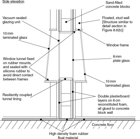
Figure 8.7 Quadruple-glazed window system
Again, as with the doors, tunnels run from the outer windows to the inner ones, fixed to the frames on the floating rooms and attached by silicone rubber to the central windows. These are usually lined with carpet to avoid chattering in the gap, and are normally made of a relatively acoustically dead material of not too great a thickness, which will allow sound to be absorbed not only by the tunnel lining itself but also by the soft materials packed around the tunnel. In this specific case, the outer panes were of 10 and 12 mm laminated glass: different thicknesses being used because each was the same width and height. They were also angled such that they would tend to reflect any sound striking them upwards, into the absorbent ceilings of each of the rooms.
It is perhaps appropriate, here, to discuss the subject of reflexion from panes of glass, or any other similar material for that matter. There is a tendency for people to think of the way that sound reflects off a hard surface in the way that light reflects off a mirror. Indeed this is the basic concept of many computerised ray-tracing concept in a crude approximation to real life. Figure 4.3 shows the case which actually applies for low frequency reflexion, and whilst it is true that the reflective pattern narrows as the frequency rises, even a narrow beam of sound projected at a window at 10 kHz will tend towards a reflected cone of energy of around 30° apex angle, as shown in Figure 8.8.
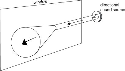
Figure 8.8 Even a very narrow, controlled beam of high frequencies will tend to reflect from a flat surface, such as a window, with a conical pattern which will not be likely to be less than 30°, even at the highest audio frequencies
Consequently, an angle of only 15° from vertical will still allow some energy emanating from the same height of the window to return to its source, but the general tendency will be for most of it to be directed in the direction of the inclination.
8.3.3 Multiple Glazing Considerations
In this instance, quadruple glazing was used in order to reduce the sound transmission through each independent wall structure, and in particular to prevent the sound from reaching the concrete wall. Effectively, the inner pair of windows was on the plasterboard layers, which in turn were isolated from the concrete wall by polyurethane foam. However, in many normal circumstances, say between two simple walls, a greater space between the windows can often be more effective than more window panes. In other words, if the space between two walls is 80 cm, then it can be more effective to use two panes of glass of, say, 10 mm and 12 mm, than to split the tunnel into spaces of 20, 35 and 25 cm by the use of four panes of mixed 10 and 12 mm glass. It is probable that the mid and high frequency isolation of the quadruple-glazing would be better, but that the low frequency isolation would be worse, as the space between the panes can be a more important factor in low frequency isolation. There are few absolute, hard and fast rules to this, as the wall structures, the degree of possible angling of the glass panes, and the type of work in which the studio is usually engaged will all add their own special conditions. For example, a voice-over studio, or a talk studio, is unlikely to be placing great importance on very low frequency isolation, because low frequency sounds are not likely to exist at high level on either side of the window. In this case, the quadruple glazing option may be preferred, whereas for a studio mainly producing dance music, with lots of low frequencies, then quite possibly the double glazing/larger space option would be preferable. Each case must be assessed individually.
Figure 8.9 shows some interesting results first published by Inman in 1994.2,3 It shows the measured results from examples of single and double glazing made with similar and different thicknesses of glass and spacings. Now 4 mm glass is not something that one often encountered in studios, but in principle it is worth noting how the double-glazed unit with 4 mm glass is actually worse in isolation between about 200 Hz and 700 Hz than a single pane of the same 4 mm glass. The results also show clearly how the increased spacing of the 4 and 6 mm glass (150 mm) gives far superior results to the 10 and 6 mm glass with only a 12 mm spacing.
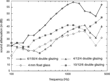
Figure 8.9 Sound transmissions versus frequency for single and double-glazing. (After Inman.)
In fact, if absorption can be placed above, below, or at the sides of the tunnels which flexibly join the glasses, a significant improvement in isolation can be achieved, but this needs to be done without compromising the isolation by causing any contact between the floated walls. One must also be careful not to leave any spaces which may allow insects to enter, or a miniature zoo may be the result after a few months. Desiccants, of course, are totally unnecessary because no condensation can exist in double glazed windows between the internal walls of adjacent rooms. Desiccants are only relevant in window systems in exterior walls, though usually vacuum-sealed panes on the outside wall is a better solution.
8.3.4 High Degrees of Isolation
There is obviously no need to produce isolation in a window system that is any greater than the isolation provided by the walls which they penetrate. A 70 dB window system in a 55 dB wall system only succeeds in wasting money. However, if very high isolation window systems are required, they may become absurdly expensive. Eastlake Audio4 installed a window system in Belgium, where an isolation of 80 dB was required between the control room and the studio. The glass panes were 11 cm thick (yes, centimetres!), and weighed almost 1 tonne each. Eleven centimetres was the maximum that the local glass making machines could stand the weight of, and the transport was very difficult. The original specification called for 14 cm glass, but when it was found that it could not be acquired in Europe, panes of 11 cm were used with a greater space between them than had originally been planned. The cost of all of this is better not to even contemplate. In fact, the total weight of the two rooms at Galaxy, floated on steel springs, is almost 2000 tonnes, with 9 tonnes of rubber in the walls. It is certainly impressive, but such would hardly be practical solutions in most cases. In fact the following quotation from David Hawkins, the owner of Eastlake Audio, just about sums up the reality. ‘Normally, when people ask for isolation figures of this type (80–85 dB), I generally suggest that they build the rooms in different streets.’
Conventional hinged doors also pose their problems. However, doors are usually able to be positioned in areas of the structure which are less critical than the normal window locations. What is more, right-angled bends and isolation vestibules can often be incorporated into the designs of door systems. In general, doors need to be heavy, acoustically lossy, and well sealed into their frames, but perhaps an extreme case can once again be outlined by describing the doors at the above mentioned Belgian studio. They used industrial doors with a nominal isolation value of 55 dB, which were employed either in pairs, or in triple sets between critical areas. Each door weighed 300 kg, and was suspended on ball bearing hinges. When the closing handles are turned, they apply a pressure of 400 kg on the door seals. A discussion of more typical studio isolation doors can be found in Section 8.8.
It is often difficult to get the fact across to people that 70 dB or 80 dB of isolation demands the same degree of treatment, irrespective of the purpose for which it is needed. ‘But I only want it for practising my drums’ is a cry so frequently heard. It is as though people expect that the cost of isolation somehow reflects the cost of what they are doing. Because they are only spending the cost of a drum kit, they expect that the isolation to the bedroom of a neighbour will somehow be cheaper than if they were spending a hundred times as much on a complete set of studio equipment. Obviously, (or at least it should be obvious) the two situations will have identical isolation requirement, whether the drums are used for practice only, or for a very serious recording process. Basically there are only two factors involved in extreme cases of sound isolation; great weight or great distance, but the isolation between rooms can easily be destroyed by inappropriate door and window systems. Anyhow, now that we have dealt with some of those door and window considerations, we can return to other aspects of acoustic design. However, in Section 8.8 we will take a more detailed look at acoustic door design.
8.4 The Geddes Approach
In Studio Two of the layout shown in Figure 8.5, one great problem was how to introduce life into the room without creating any boxiness in the recorded sound. Figure 8.6 shows a floor plan, with the dotted line showing the line where the angled wall strikes the ceiling. Figure 8.10 shows a side elevation of the room. From these figures it can be seen that the wall opposite to Studio One is double-sloped. Dr Earl Geddes,5 proposed this double-sloped wall concept in an otherwise rectangular room, initially for the more even distribution of modal energy in control room shells. Nevertheless, the technique seems to provide a useful solution to some of the more intransigent small recording room problems.
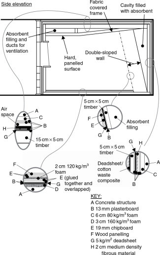
Figure 8.10 Isolation and acoustic treatment details of a small ‘Geddes’ room
Essentially, the double slope allows a relatively steeply angled wall surface without undue loss of floor space, although this is all in relation to the room size. The steep angling tends rapidly to steer the modal energy into the oblique form, which passes round all six room surfaces. On each contact with a wall, a sound wave will lose energy by absorption, and that absorption tends in many cases to be greater for waves striking the surfaces at oblique angles than for perpendicular impacts. The oblique modes also strike more surfaces more often, which also contributes to the increased absorption. By making all surfaces absorbent, other than the glass, the wooden floor, and the double-angled wall, the modal energy can be suppressed very quickly.
Figure 8.11 shows the room in typical use with Control Room Two. In this situation let us assume that voice replacement work is being done. The person speaking, or singing, is facing the double-sloped wall. The wall is panelled with wood strips, to add life to the room, and into it has been recessed a monitor television for voice synchronisation. The whole wall is hard, but only little reflected energy reaches the vocal microphone because the window behind the vocalist is angled steeply upwards, and deflects much of the energy into the absorbent ceiling. What is more, when the room is being used in this way, it is often desirable to draw curtains across the window. This gives more privacy between the two studios, and the curtains, heavy and deeply folded, help to suppress reflexions. The double-angled wall is of a relatively lightweight construction, and the whole cavity behind it is filled with mineral wool and scraps of felt and deadsheet, which press against the rear of the wall to provide considerable damping. The cavity itself is heavily damped by the filling.
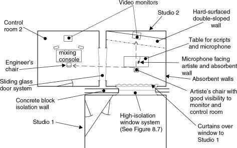
Figure 8.11 Studio 2 in use for voice-overs
If we now consider this room one frequency band at a time, we will see how the overall design is effective for wideband control. Due to the geometry, the mid and high frequencies can find no simple, effective, reflective path back to the microphone. The upper range of the low frequencies, for which the angling of the window may be insufficient, are not reflected much by the sloping wall, and either pass through into the great depth of absorbent filling or are absorbed by the highly damped panels of the wall structure itself. The very low frequencies are in the pressure zone of the room, so are in any case rapidly lost. The pressure zone frequency for this room is about 65 Hz. Visibility between the engineer and vocalist is good. Each can face their own video monitors, and with just a small turn of the head can see each other clearly.
In the case of the room being used in conjunction with Studio One, the musician, in this case let us presume that it is a drummer, will face away from the double-sloped wall. This will give direct visibility to Studio One and on through to Control Room One. There is also excellent visibility to Control Room Two in the event that it should be being used as an additional isolation room. This situation is shown in Figure 8.12, and it can be seen that the microphones around the drum kit are generally pointing backwards and downwards. They are thus pointing not only at the drums, but also towards the reflective floor and double-sloped wall, and hence will pick up a great deal of early reflected energy which will ‘fatten’ the sound of the drums. The drum kit will not sound the same as a kit recorded in a live room, nor of one recorded in a large room, but it will certainly, for many types of music, be preferable to the recording of a kit in either a more conventional small room or in a dead room. There will be a more potent drum sound and more ‘feel’ for the drummer than would be the case in a small dead room, and yet only very low levels of unnatural room colouration result. The room does not possess the small-room ‘boxiness’ which spoils so many recordings, and has been very well received by musicians and recording engineers.
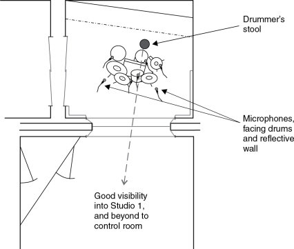
Figure 8.12 Studio 2 in use in conjunction with Studio 1
8.5 Recording Techniques for Limited Acoustics
In the small studio complex depicted in Figure 8.5, the main recording area was relatively live, having windows to Control Room One and to Studio Two on two of its sides (its two ends), and a large window to the outside on another side. This wall was of angled brickwork, installed in a saw tooth arrangement, and faced a dead wall on the other long side of the room. The floor was of wood, over which rugs could be laid if required, and the ceiling was ‘V’ shaped, being hard at the side nearest to the control room, progressing to soft at the Studio Two side. The room contained a grand piano, the open lid of which could face the hard surfaces if a rich tone was called for, or could face the absorbent ‘trap’ wall if more separation was needed, such as when recording a jazz quartet or similar.
In this room, other than with the laying down of rugs or the use of movable acoustic screens, there was little variability provided, as the owners deemed the range of rooms that they had to be sufficient for all of their normal needs. Because they had insisted on such high degrees of sound isolation, and considerable space had therefore already been consumed by the massive structures, they did not want to lose any further space by the installation of systems of variable acoustics. Nevertheless, despite the lack of variability, they have a variety of ways to circumvent the restrictions of limited acoustics.
8.5.1 Moving Musicians and Changing Microphones
Figure 8.13 shows a stereo pair of microphones in a room with an appropriate ambience. If it is desired that two vocalists build up the sound of ten by means of five unison or harmonised recordings, then instead of grouping them around a single microphone and panning the different tracks into different locations on the stereo mix, a single stereo pair of microphones can be positioned at the chosen spot in the room. The vocalists then move into different locations for each take. If ten recording tracks are available for this, each stereo pair would be panned left and right in the mix, or to whatever other desired position, and the spread of panning would be built up automatically. Usually, the sound of such recordings is much more spacious, powerful, and natural than the ‘five, panned mono tracks’ approach. If ten tracks are not available, and especially if digital recorders are used and noise build-up and generation loss are not problems, each subsequent recording can be mixed with the playback of the previous recordings, carefully balanced of course, and recorded onto another pair of tracks. The previous pair of recorded tracks can then be used for the next ‘bounce’, and so forth. This way, only four tracks are used, and anything which may be needed to ‘repair’ the final build-up, such as earlier takes which are subsequently considered to need reinforcing, can be recorded separately on the last but one pair, and left separate till the final mixdown. By the use of this technique there is no extra ambient build-up, because no extra energy is driven into the room by recording five pairs of vocalists separately than by ten vocalists singing simultaneously. The same ambient spread is also achieved in each case. It is a technique worth trying, because it reduces the build up of the same ambience on each take.
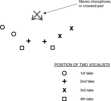
Figure 8.13 Method of creating a more natural ambience when multitracking backing vocals. This technique can create a better choir effect than merely panning voices that have been recorded in a fixed position
Techniques such as this can greatly improve the flexibility of rooms in which the quantity of acoustic variability is not great. Another possibility is to change microphones for different overdubs. If other microphones can be used which are still considered to be acceptable sounding for whatever is to be recorded, then as each microphone type has a distinctive and different polar pattern/frequency characteristic, the build-up of the room artefacts by multiple recordings in the same place can be significantly reduced. There are limits, however, because any strong room responses may still predominate.
8.6 A Compact Studio
Possibly we should end this chapter with a look at a compact studio where acoustic variability was needed along with a good degree of separation. The studio was built in London and was for commercial use. Its owner was a drummer, and, not too surprisingly, drum sounds had a strong input into the design considerations. Nevertheless, there was also great importance put on vocal recordings and electric guitars and basses. Figure 8.14 shows the overall layout. The main studio area sub-divides by the employment of hinged panels, similar to those shown in Figure 7.6, having hard surfaces on one side, and soft, absorbent surfaces on the other. The whole studio is situated in a warehouse, with relatively few problems caused by a small amount of escaping sound. It is not on a main road, so the low frequency rumble of fast, heavy traffic is no problem either. A controlled leak of low frequencies was allowed to pass into the warehouse, thus preventing excessive build-up in the smallish rooms.
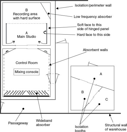
Figure 8.14 Studio in a warehouse, with external booths. With the hinged panels in the positions shown, the whole of area A/B becomes one, large live room. When the panels are swung out to the dotted line, section B remains live, but in section A, soft, absorbent surfaces become exposed, rendering the acoustic in that area much more dead. Panels can be moved individually, or partially, to change the sound or to use them as screens between instruments. The panels are quite heavy, with wheels supporting their outer ends, so isolation between sections A and B is quite reasonable when they are swung out to the dotted line. The ceiling is an inverted V-shape, with its apex above the dotted line. Over area A, it is absorbent, and over area B, finished with wooden panelling. The isolation booths, intended for high level recording of bass or guitars, are well isolated from the main studio and control room. Booths A and C are acoustically rather dead, whilst booth B is relatively live. Sliding glass doors are used to maximise the usable floor space. With windows in the control-room entrance doors, and in the side wall of booth B, visual contact between the engineer and booths B and C could be provided. If such a warehouse were not in a noise sensitive location, then the walls could be relatively lightweight, allowing a controlled leak of low frequencies, and thus giving the rooms better LF performance without the use of too much internal LF absorption. With a lighter weight construction, costs can also be greatly reduced
Drums could be recorded in the main area, in an acoustic ambience of whatever ‘liveness’ or deadness that the room could provide with its variable states. Separation for guide vocals or other instruments could be achieved by creating booths out of the hinged partitions. Outside of the main recording area, and separated from it by a corridor, is an independently floated box containing three small booths. Into these, guitar or bass amplifiers can be placed, fed from instruments in the other rooms via line amplifiers. The musicians themselves can be located in the main studio, or the control room, which can also house keyboards and their attendant musicians. Once the rhythm tracks have been laid, the main room can be re-configured for the recording of acoustic guitars, lead vocals, backing vocals, or anything which may be required for completion of the recordings. This is yet another approach to the concept of a multi-room studio with a combination of acoustics.
8.7 Review
Figures 8.1, 8.5 and 8.14 show three actual, workable, successful, but very different methods of tackling the problem of how to combine different acoustic options. The range of possibilities is almost endless, but these three examples give a feel for three very dissimilar approaches which could be variously adapted and modified to fit a wide range of likely starting conditions. Again, however, there are few absolute rules, which is why the experienced studio designers are so frequently relied upon for their expertise. Their function is not only to offer design suggestions, but also to point out things which may lead to trouble in the future. Such points are not always obvious to the clients, and the problems are often only realised after past experience has pointed them out. Hopefully, this chapter will have at least begun to point out the strength of certain concepts, together with the weaknesses of others. As it has progressed, we have been able to look at some of the decisions which have had to be made along the way. One thing is for sure; the permutations are endless.
As a final point of possible interest, the re-built version of the aborted attempt to construct the studio as depicted in Figure 8.3 is similar to that shown in Figure 7.1. The studio now incorporates a wooden live room, an acoustically dead room, and a moderately large general studio area with reflective, absorbent, and diffusive walls, not too dissimilar to the ideas outlines in Figure 5.18. It works well, and it also ended up costing far less to build than the €60,000 which had already been spent on the partial completion of the originally proposed design.
The idea of yet another whole studio concept is illustrated in Figure 8.15. As shown in Figure 8.15(a), the studio takes the form of a ‘village’ within a building. The hexagonal room in the centre of the photograph is a vocal room, which leads off a granite live room. The main neutral recording room is beyond, with skylights rising above it. At the back, with an external entrance on the right of the photograph, is the control room. The balcony from where the photograph was taken has facilities for the preparation of food and drink, and also incorporates a lounge area with satellite television projected on to a large screen. The idea behind the design was to take the musicians into a self-contained space, isolated from the outside world, in which they could relax in absolute privacy. Despite the sense of spaciousness and tranquillity, it is less than 30 m from a busy commercial street, with shops and many restaurants of different ethnic origins.
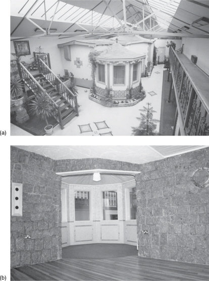
Figure 8.15 The Pink Museum, Liverpool, UK (1988). (a) The studio takes the form of a village within a building. (b) View from the stone room into the vocal room, which can be fitted with curtains when necessary. This room can be seen in the centre of photograph (a)
8.8 Typical Isolation Door Construction
In many cases, people without sufficient experience opt for ‘seemingly’ high isolation industrial doors, but their high degrees of isolation may not extend to low frequencies. It should be remembered that few industrial processes produce 115 or 120dB SPL in the 40–80Hz band, but such levels in a rock music studio are quite normal. The isolation curve of a 37dB ‘acoustic’ door is shown in Figure 8.16. Indeed, in the mid frequencies the isolation is over 37dB, but below 100Hz it is only 20dB, and falling with frequency. Thus, at 60 or 80Hz with 120dB SPL on one side of the door one could expect 100 dB, or so, on the other side – hardly high isolation! Obviously, with two such doors and a decent space in-between them, perhaps 50 or 60dB of isolation could be achieved, but that may still allow 60dB SPL on the other side of the door system.
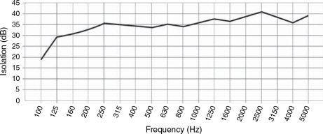
Figure 8.16 Door isolation versus frequency. Isolation plot of a nominally ‘37dB’ acoustic isolation door. Note how below 250Hz the isolation begins to fall. Standard isolation graphs such as this one rarely quote isolation below 125Hz, and often the isolation around 50–63Hz can be much lower than the nominal isolation figure, which approximates to a dBA curve
If extreme isolation is needed then the 300 kg doors, described in Section 8.3.4 may be needed, but much success has been achieved with double door systems made from plywood sandwiches as shown in Figure 8.17. The doors also look a lot more ‘creative’ than industrial doors; a point which is worth considering in an artistic environment. (However, in radio stations or voice studios, ready-made doors may be an easy solution because low-frequency isolation is not usually an issue in these recording environments.) Another advantage of the doors shown in Figure 8.17 is that they can be made to measure, and can usually be made by a carpenter for considerably less than the cost of buying the industrial style doors.
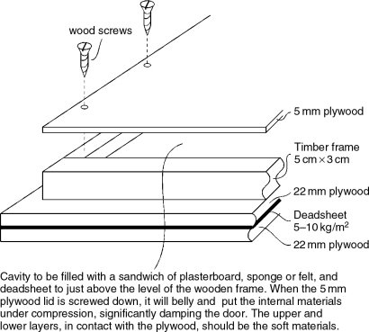
Figure 8.17 Acoustic doors
Figure 8.18 shows the hydraulic closing systems which are suitable for such doors. When used in conjunction with simple grab handles, to pull the doors open and closed, the hydraulic retainers also act as shock absorbers, making it impossible to slam the doors against the frames. The retainers should be positioned in the top, centre of the doors unless structural restrictions necessitate alternative locations.
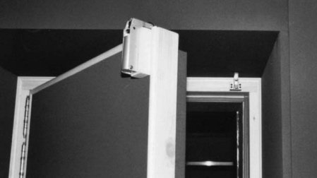
Figure 8.18 The hydraulic brake on the door engages with the hook on the frame when the door is closed. A hydraulic damper controls the rate at which the door can close the last few centimetres (as the roller on the brake is forced vertically upwards by the shape of the hook). Once ‘over centre’ the hydraulic ram works in the opposite direction, forcing the roller upwards and maintaining the door tightly closed
For the greatest flexibility in recording, a range of different acoustic spaces is desirable.
Many things need consideration, such as the control room requirements, inter-room visibility, and ease of access to frequently used areas, for example vocal rooms.
Specialist studio designers tend to have much more knowledge about such needs than general acousticians.
Building a studio correctly usually costs no more than building it incorrectly. Inter-room visibility is important, but it should normally not be allowed to compromise the acoustic needs of the rooms.
Closed-circuit television systems based on cathode-ray tube technology can create problems with their time-base whistles.
Triple glazing is not always preferable to double-glazing. Double glazing with a large space between the panes can be better at low frequencies than triple glazing in the same overall space.
Window panes should be of different sizes or thicknesses, to avoid weak spots in the isolation at the frequencies of coincident resonances.
Door and window systems generally do not need to achieve isolation any greater than that of the walls which they penetrate.
The need for very high degrees of isolation can lead to greatly increased costs.
Double-sloped walls can be used in small rooms to drive modes into the oblique, more ‘lossy’ form, without using too much floor space.
When rooms have only limited acoustic flexibility, microphone and recording techniques can introduce an extra degree of variability into the recording process.
References
1 Newell, Philip, Recording Spaces, Focal Press, Oxford, UK (1998)
2 Inman, C., ‘A Practical Guide to the Selection of Glazing for Acoustic Performance in Buildings’, Acoustics Bulletin, Vol. 19, No. 5, pp. 19–24 (September/October 1994)
3 Howard, David M. and Angus, James A. S., Acoustics and Psychoacoustics, 2nd Edn, Focal Press, Oxford, UK, p. 319 (2001)
4 Schoepe, Zenon, ‘Galaxy’, Studio Sound, Vol. 36, No. 10, pp. 42–4 (October 1994)
5 Geddes, Earl, ‘An Analysis of the Low Frequency Sound Field in Non-Rectangular Enclosures using the Finite Element Method’, Ph.D. dissertation, Pennsylvania State University, USA (1982)