
Rooms with Characteristic Acoustics
Unusual recording environments. The influence of the environment on the musicians and the music. The search for special sounds. The negative effects of a containment shell. The sounds of different construction materials. The effects of the directional characteristics of loudspeakers and microphones. Stone rooms. Acoustic and electronic reverberation characteristics. The 20% rule. Reverberant verses bright rooms. Low frequency considerations. Orchestral rooms. Psychoacoustics and spacial awareness. Dead rooms. Foley rooms.
6.1 Definitions
From Morfey’s Dictionary of Acoustics1:
Dead room: A room in which the total absorbing area approaches the actual room surface area. Note that such a room cannot qualify as ‘live’; compare live room.
Live room: A room in which the amount of sound absorption is small enough that the mean free path LAV ![]() is greater than, where A is the room absorption.
is greater than, where A is the room absorption.
Room absorption: A measure of the equivalent absorption area of a room – units, m2.
(For ‘mean free path’ see Section 4.4.1.)
The above definitions are quoted because there is a growing tendency, due to the popularisation of recording, to refer to any room in which musicians play together as a ‘live room’ because they play live, as opposed to recorded. Throughout this book, the term live room is used in its acoustical sense – a room with considerable acoustic life; neither neutral nor dead.
6.2 A Brief History of Idiosyncrasy
In the early days of recording, when studios were expected to be able to handle any type of recording which their size would allow, live rooms were more or less unknown. To this day, if the only recording space in a studio isa live room, then it is either in a studio which specialises in a certain type of recording, or the room is used as an adjunct to a studio which is mainly concerned with electronic music. Live rooms are distinctly individual in their sound character, and tend to impose themselves quite noticeably upon the recordings made in them. However, when that specific sound character is wanted, then effectively there is no substitute for live rooms. Electronic or other artificial reverberation simply cannot achieve the same results, a point which will be discussed further in Section 6.7.
When, in the late 1960s, many British rock bands began to drift away from the more ‘sterile’ neutral studios, gravitating towards the ones in which they felt comfortable and in which they could play ‘live’ in a more familiar sonic environment, a momentum had begun to grow which would radically change the course of studio design. In 1970 the Rolling Stones put the first European 16-track mobile recording truck into action. This was not only intended for the use of live recordings, but also for the recording of bands in their homes, or anywhere else that they felt at ease. It was soon to record the Rolling Stones Exile on Main Street album in Keith Richard’s rented house, Villa Nelcote, between Villefranch-sur-Mer and Cap Ferrat in the south of France, but another of its earliest uses was the recording of much of Led Zeppelin’s fourth album. This album was a landmark, containing such rock classics as Stairway to Heaven and When the Levee Breaks; the latter perhaps inspiring a whole generation of recorded drum sounds. Previously, Led Zeppelin had made many recordings in the famous, old, large room at Olympic, in London. For the fourth album, they rented Headley Grange in Hampshire, England, and took along the Rolling Stones’ mobile, and engineer Andy Johns. The house had some large rooms, but none had been especially treated for recording. Nevertheless, as the house existed in a quiet, country location, the ingress and egress of noise was not too problematical.
6.2.1 From a Room to a Classic
It seems that When the Levee Breaks, with its stunning drum sound for the time, was never planned to be on the album, or indeed to be recorded at all. In the room in which they were recording, John Bonham was unhappy with the sound of his drum kit, so he asked the road crew to bring another one. When it arrived, they duly set it up in the large hallway, so as not to disturb the recording, and waited for John to try it. At the next available opportunity, he took a break from recording and went out into the hallway to see if he preferred the feel and sound of the new kit. The other members of the band remained in their positions, relaxing, when suddenly a huge sound was heard through their headphones. The sound was from the drum kit in the hallway.
John had failed to close the door when he went out, and the sound from the kit that he was playing was picking up on all the open microphones in the recording room. The hall itself had wood panelled walls, with a large staircase, high ceiling, and a balcony above. It was thus diffusive, absorbent to low frequencies, reverberant, well supplied with both late and early reflexions, and very much of a sonic character which matched perfectly the style and power of the drumming. He went into a now famous drum pattern, over which Jimmy Page and John Paul Jones began playing some guitar and bass riffs which they had been working on. Robert Plant picked up on the whole thing, and sung along with some words of an old Memphis Minnie/Kansas City Joe McCoy song. Subsequently, Andy Johns, who had been recording the sounds out of pure interest, reported from the mobile recording truck that they should consider this carefully, as he was hearing a great sound on his monitors.
Such was the birth of this classic rock recording. The story was related to the author by Jimmy Page, a dozen years or so after the event, during a telephone conversation relating to the production of some recordings for Tom Newman (co-producer of Mike Oldfield’s Tubular Bells I & II), as one of the songs being recorded was the one referred to above. The problem related to the fact that no matter how many times Newman listened to the Led Zeppelin version, he could make absolutely no sense of the words in the bridge section. ‘Probably that is because they don’t make sense.’ replied Jimmy. Evidently, during Robert’s sing-along, there was no bridge lyric which he knew or remembered, so he sung what came into his head. Why this story is relevant to this chapter is because it shows, most forcefully, how a room inspired an all-time rock classic. It is almost certainly true to say that without the sound of the Headley Grange hallway, Zeppelin’s When the Levee Breaks would never have existed.
Had Led Zeppelin been recording in a conventional studio of that time, they could perhaps now have been considered to be one rock classic short of a repertoire. But, it must also be remembered that had John Bonham been playing a different drum pattern in Headley Grange, or had Jimmy Page and John Paul Jones opted for a different response, then the sound of the drums in the hallway may have been totally inappropriate. This highlights the limitation with live rooms; they can be an inspiration and a unique asset in the creation of sounds, or they can be a totally intrusive nuisance. Furthermore, there is no one live room which will serve all live room purposes.
6.2.2 Limited, or Priceless?
Let us suppose that we had a reverberation chamber, similar to the ones used for acoustic power measurements in universities, institutes, and research departments. These are constructed to give the broadest achievable spread of modal resonances, in order not to favour any one frequency over another. They can produce excellent results as reverberation chambers for musical mixes, but they lack the specific idiosyncratic characteristics that make special live rooms special. Let us now consider an analogous situation. Imagine that guitar manufacturers were to opt for a totally even spread of resonances in their instruments; to have ‘life’, but as uniformly spread as possible. All of a sudden, almost all guitars would begin to sound much more alike than they currently do. In general, it is impossible to make a Fender Stratocaster sound like a Gretch Anniversary, or vice verse, because the time domain responses of the resonances and internal reflexions cannot be controlled by the frequency domain effects of an equaliser. Something halfway in between a Stratocaster and an Anniversary would be neither one thing nor the other, and whilst it may well be a valid instrument in its own right, it could not replace either of the others when their own special sounds are wanted.
Another analogy exists here in that most professional guitarists have a range of instruments for different purposes: different music, different arrangements, different styles, and so forth. Such is the case with live rooms, where a ‘universal’ room could perhaps be used as an acoustic reverberation chamber for the recording and mixing process, but it could never be used to substitute for the special sounds of the special rooms. What is more, no large, selfrespecting recording studio has banks of identical ‘best’ electronic reverberation devices, but rather a range of different ones. It is generally recognised that a range of different artificial reverberation is greatly preferable to more of ‘the best’. In so many cases, neutrality is quite definitely not what is called for.
Dave Purple, who was formerly at dbx in Boston, USA, related a story about the reverberation plates in Chess Studios. In the 1960s, he used to be an engineer at Chess Records in Chicago, when they had the big EMT 140 electro-mechanical reverberation plates. These consisted of spring mounted steel sheets, about 2 m by 1 m, with an electromagnetic drive unit and two contact pick-ups. Dave described how they used to heat the room where the plates were kept to about 30 °C, then tension the plates. When the room cooled down on removal of the heaters, and if they were lucky and the springs did not snap as the steel contracted, the plates produced a unique sound. More often than not, however, the springs did snap, and the whole process would have to be tediously repeated until it succeeded in its aims. Some of the recordings which inspired many people in this industry were the Chess recordings of Bo Diddley and Chuck Berry. This was partly due to their powerful and distinctive music, but partly also for their unusual sounds. Somewhat unusually, for the time, the Rolling Stones went to Chicago specifically to record in the old Chess studios at 2120 South Michigan Avenue, and its unique sounds can still clearly be heard on a number of their older recordings.
The old EMT plates were very inconsistent, and though their German manufacturers guaranteed their performance within a quite respectably tight specification, the sonic differences achievable within that specification were enormous. What Chess were doing would have had the EMT engineers tearing their hair out, but it got Chess the sound which was a part of their fame, so in such circumstances specifications were meaningless. The irony here is that whilst EMT were trying to make widely usable, relatively neutral plates, Chess were doing all they could to give their plates a most definitely un-neutral sound. This situation was a perfect parallel to what was happening in the development of live-rooms for studios, where the musicians and engineers were looking for something other than what the then current room designers were offering them.
Perhaps it would be appropriate to relate a few more personal experiences at this juncture. I recall in 1978, when building The Townhouse studios in London, desperately trying to buy a specific EMT 140 plate from Manfred Mann’s Workhouse studios. I had done some recordings there for Virgin Records, and had been impressed by the sonic character of one of their plates in particular. I offered them a really ludicrously large amount of money for the plate, but short of buying the whole studio, towards the success of which the plate had no doubt contributed, there was no way that Manfred Mann and Mike Hugg would sell it. In fact at one stage, I actually did come close to aquiring on the whole studio, which also had a wonderful sounding API mixing console.
In the Silo studios in West London, in the early 1980s, they had intended to build a large studio room with a small drum room, connected to the studio via a window. The proposed drum room was about 3.5 m × 2 m, and about 2 m high, which in fact was far too small for the purpose. However, this was happening right at the time when the backlash against small, dead, isolated drum rooms was reaching a peak, and once the owners realised that their ideas were out of date they stopped work on the room. When the studio opened, the proposed drum room remained just a concrete shell, with a window and a heavy door. I recorded some of the best electric rock guitar sounds that I have ever recorded with amplifiers turned up loud in that room. This pleased the owners, as their ‘white elephant’ had become a great guitar room. The density of reflexions when the room was saturated with an overdriven valve (tube) amplifier combo was stunning. The ‘power’ in the sounds, even when heard at low level in the final mixes, was very impressive, yet the problem with this room was that for almost any other purpose it was a waste of space. Neither this room, nor Manfred Mann’s plate, nor the Chess plates, nor the Headley Grange entrance hall would have had any significant place in a large recording studio complex outside of their uses with certain very specific types of music and instrumentation.
In another instance, I was fortunate enough to be one of the engineers on a huge recording of Mahler’s Second Symphony for film, television, and what is now one of the CBS ‘Masterworks’ CD series. It was performed by the London Symphony Orchestra, the 300 piece Edinburgh Festival Choir, two female soloists, an organ, and an ‘off stage’ brass band. It all took place over four days in Ely cathedral, England, which the conductor, Leonard Bernstein, had specifically chosen for its acoustics and general ambience. This was a masterful choice by a genius of a conductor, but despite the wonderful acoustics of the cathedral for orchestral/choral purposes, it would have been entirely unsuitable for any of the other recordings discussed so far in this chapter. They would simply have been a mess if recorded there. Yet, conversely, perhaps there was no studio that could have hoped to achieve a recording with the sound which we captured in the cathedral.
The Kingsway Hall in London was an example of another great room for the recording of many classics, despite its sloping floor and problems from the noises of underground trains, aeroplanes, and occasional heavy traffic. It was an assembly hall, never specifically designed for musical acoustics, yet it far outstripped the performance of any large orchestral studio in London at the time.
Many specifically designed concert halls have been criticised for their failure to live up to their expected performance, though such criticism has not always been fair. Concert halls must cater for a wide range of musical performances, so they tend to some degree to have to be ‘jacks of all trades’ rather than the ‘masters of one’, the latter of which is perhaps more the case with Ely Cathedral. To experience Mahler’s Second Symphony in Ely, or to have heard some Stockhausen in Walthamstow town hall, would show just how appropriate those recording venues were; but Stockhausen in Ely Cathedral? . . . Perhaps not!
Unfortunately, though, purpose-built concert halls would be expected to reasonably support both, at least adequately, if not optimally. As yet, one cannot design a general purpose concert hall or recording studio to equal the specific performances of some accidentally discovered recording locations for certain individual pieces of music. Neither can one build one live room to equal the performances of Headley Grange, The Silo’s concrete room, Manfred Mann’s plate, or the one in the old Chess Studios. Brass bands, chamber orchestras, symphony orchestras, choirs, organs, folk music, pan pipes, and a whole range of other instrumentation or musical genre all have their own requirements for optimum acoustic life. The bane about the ‘best’ live rooms is that they gain their fame by doing one thing exceptionally well, but for much of the rest of the time they lie idle. If one is not careful, they can be something of an under-used investment, which is why many studio owners opt to use whatever limited space they have for rooms of more general usability.
The complexity of the acoustic character of live rooms is almost incomprehensible, and they are often designed on intuition backed up by a great deal of experience, as opposed to any rules of the thumb or computers. Just as no computer has yet analysed the sound of a Stradivarius violin and shown us how to build them, full computer analysis of what is relevant in good live rooms is beyond present capabilities: the modelling of surface contours is not possible unless the position and shape of every surface irregularity is known in advance, and in great detail. Designs are thus usually ‘trusted’ to designers with experience in such things, but in almost every case, some engineer or other will declare the result ‘rubbish’ because it fails to do what he or she wants it to do, and there is no knob to change the setting. The lack of fixed specification means that the value of such rooms is largely dependent upon taste.
6.3 Drawbacks of the Containment Shells
The question is frequently asked as to why so many great acoustics are found in places not specifically designed to have them, and why so many places which are specifically designed are frequently not so special. For example, why is the fluke sound of the entrance hall at Headley Grange so difficult to repeat in a studio design? Well, part of the problem was discussed in Chapter 4. Studios tend necessarily to be built in isolation shells which reflect a lot of low frequency energy back into the room. This reflected energy must then be dealt with by absorption, which in turn takes up a lot of space and generally changes the acoustic character of the rooms to a very great degree. The old Kingsway Hall, in London, was used for so many classical recordings because of its very special acoustic character, but its drawbacks were tolerated in a way which they never would be in a recording studio. Many good takes were ruined by noise and had to be re-recorded, but because it was not a recording studio, this was a hazard of the job. Conversely, a purpose-built recording studio with similar problems would be open to so much argument and litigation that it would not be a commercial proposition. Even if it had the magic sounds, people would not tolerate such problems in a building actually being marketed as a professional studio; their expectations would be different.
The Kingsway Hall had windows through which many noises entered; as they also did through the floor and general structure. However, these were the selfsame escape routes which allowed much of the unwanted sounds to leave, such as the sounds which would cause unwanted low frequency build-ups. Structural resonances could, in turn, change the sound character, and remember, once again, that most instruments were developed for sounding at their best in the normal spaces of their day. Once we build a sound containment shell and a structurally damped room, we have a new set of starting conditions. However, if we are to operate a studio commercially, without disturbance to or from our neighbours, and offer a controlled and reliable set of conditions for the musicians and recording staff, such a containment shell is an absolute necessity.
If we consider again the entrance hall at Headley Grange, it is a relatively lightweight structure which is acoustically coupled via hallways, corridors and lightweight doors into a rabbit warren of other rooms. Effectively, the sound of the hallway is the sound of the whole Grange, and if we were to contain the hallway in an isolation-shell and seal all the doors and windows, then we would end up with a room having a very different sound to the one which it actually has. It would be rare, indeed, to find a client for a studio design who would provide a building the size of a mansion house only to end up with a recording space the size of its hallway, yet this is what it would possibly take to create a sonic replica.
There is also another aspect of recording in live rooms which, whilst unrelated to acoustics, is so fundamental in their use that it should be addressed. Reproducing the exact acoustic of Headley Grange would not guarantee a Led Zeppelin drum sound. There were five other very important factors in that equation. John Bonham, his drums, the other members of the band, the song, and the engineer Andy Johns. Designers are often asked to produce rooms which sound like some given example, but in the case in point, John Bonham was a drummer of legendary power, and he also had the money to afford to buy good drum kits. The engineer, Andy Johns, the brother of another legend, Glyn, had been well taught in recording techniques. He also had the excellent equipment of the Rolling Stones mobile truck at his disposal, and considering his brother’s fame, perhaps also had a natural aptitude and a pair of musical ears. He knew where to put microphones, and where not to put microphones. He trusted his own ears and decisions, and he had excellent musicians and instruments to record.
Hopefully this point is not being unduly stressed, but a great live room is not a magic potion in its own right. It can enhance the performance, or even, as we have seen, inspire the performance of musicians, but nothing can substitute for starting off with good musicians, good instruments, good recording engineers and good music. Good recording equipment is also important, but is generally secondary to the previous items. Good and experienced musicians will react to a good room, and play to its strengths. They will not simply sit there playing like robots. The whole recording process is an interactive process, hence the care which must be taken to avoid anything which could make the musicians uncomfortable.
6.4 Design Considerations
When designing live rooms it is often necessary to re-create the acoustic of a more usual space within a very unusual shell, and this may in itself require some unusual architecture. The materials which are used to create these internal acoustics are very important in terms of the overall sound character of the rooms. Wood, plaster, concrete, soft stone, hard stone, metal, glass, ceramics and other materials all have their own characteristic sound qualities. Within the range of current response specification, it may be almost impossible to differentiate between the response plots of rooms of different materials in terms of determining from which materials they were made. Yet the ear will almost certainly detect instantly a woody, metallic, or ‘stony’ sound. In general, all the above materials are suitable for the construction of live rooms, and it is down to the careful choice of the designer to decide which ones are most appropriate for any specific design. The overall sound of the rooms, however, will tend to have the self-evident sound quality associated with each material. Wood is generally warmer sounding than stone, and hard stone is generally brighter sounding than soft stone. Geometry and surface textures also play great parts in the subjective acoustic quality.
6.4.1 Room Character Differences
For this discussion, live rooms should now be split into two groups; reflective rooms and reverberant rooms. The former tend to have short reverberation times, but are characterised by a large number of reflexions which die away quickly. The reverberant rooms tend to have a more diffusive character, with a smooth reverberant tail-off. The reflective ‘bright’ rooms also often employ relatively flat surfaces, though rarely parallel, and they often contain a considerable amount of absorption to prevent excessive reverberant build-up. The reverberant rooms on the other hand tend to employ more irregular surfaces and relatively little absorption. It is possible to combine the two techniques, but the tendency here is usually towards rooms which have very strong sonic signatures, and consequently their use becomes more restricted.
The question often seems to be asked as to why flat reflective surfaces in studios usually sound less musical than they do in the rooms of many houses or halls. Notwithstanding the isolation shell problem, studios rarely have the space-consuming chimney breasts, staircases, furniture, and other typical domestic artefacts. These things are all very effective in breaking up the regularity of room reflexions, but studio owners usually press designers for every available centimetre of space. As mentioned in Section 5.3.4, it would seem that far too many of them are more interested in selling the studio to their clients on the basis of floor space rather than acoustic performance. (Never mind the sound, . . . look at the size!) Perhaps this is to a large degree the fault of the ignorance of the clients as much as that of the studio owners. There is possibly too much belief today in what can be achieved electronically, and the importance of good acoustics is still not appreciated by a very large proportion of studio clients. Of course, those who do know tend to produce better recordings, by virtue of having had the luxury of better starting conditions, and leave the mass market wasting huge amounts of time trying to work out exactly which effects processor program they used in order to get that sound. The answer of course is that good recorded sound usually needs little or no post-processing, unless, that is, the processed sound is the object of the recording.
There are almost no absolute rights or wrongs in terms of live room design, and it seems that whatever a designer provides, there will always be people coming along who have heard ‘better’ elsewhere. Nevertheless it is also surprising how one famous recording made in a room will suddenly reverse the opinions of many of the previous critics, who will then flock to the studio for the ‘magic’ sound. Creating good live rooms is like creating instruments, certainly to the extent that the skill, intuition, and experience of the designer and constructors tend to mean more than any text-book rules. It is also difficult to give a list of taboos, because almost every time that something could be considered to be absolutely out of the question for wise room design, an example of a well-liked room can be found which apparently flouts the rules. Large live rooms are unusual in that, beyond their existence in a somewhat acoustically controlled form, as, for example, the rooms used for selected orchestral recordings, they are normally to be found outside of purpose-designed recording studios. Their use tends to be too sporadic to allocate such a large amount of space to occasional use. It is usually via mobile recording set-ups that the benefits of these rooms are enjoyed.
6.5 Driving and Collecting the Rooms
Smaller live rooms do at least appear to have one thing in common; recording staff must learn how to get the best out of each one individually. The modal nature of such rooms defies any reasonable analysis: the complexity is incredible. The positions of sound sources within the rooms can have a dramatic effect on determining which modes are driven and which receive less energy. An amplifier facing directly towards a wall will, in all probability, drive some axial modes very strongly. However, precisely to what degree they will be driven will depend upon such things as the distance between the amplifier and the facing wall, and whether the loudspeaker is in a closed box, or is open backed.
Positioning a closed-back loudspeaker on an anti-node, where the modal pressure is at a peak, will add energy to the mode, and the room will then resonate strongly at the natural frequency of the mode. Placed on a node, where the pressure is minimal, that mode will not be driven, and its normally strong character in the overall room sound will be overpowered by other modes. Positions in-between will produce sounds in-between. If the cabinet is open backed, it will act as a doublet, (or figure-of-eight source) radiating backwards and forwards, but very little towards the sides. A closed back cabinet at lower frequencies, say between three or four hundred hertz, will radiate omni-directionally and will drive the low frequency axial modes of all three room axes, that is, floor to ceiling, side-wall to side-wall, and front-wall to back-wall. With an open back however, only one axial mode will be driven, in the axis along which the loudspeaker is facing. What is more, because the output from the rear of the cabinet is in anti-phase to the frontal radiation, it acts as a pressure-gradient source, and not a volume-velocity source, so it couples to the velocity anti-nodes, which are the pressure nodes. Open and closed-back cabinets therefore drive the room modes very differently. Figure 6.1 shows the typical radiating pattern of open and closed backed cabinets.
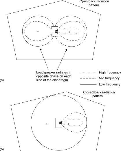
Figure 6.1 Comparison of open and closed back loudspeakers in the way that they drive the room modes. (a) High frequencies propagate in a forward direction, but low and mid frequencies largely radiate in a figure of eight pattern. (b) As in the above case, the high frequencies still show a forward directivity. However, in this case, the mid frequencies also radiate only in a largely forward direction, but the low frequency radiation pattern becomes omni-directional
Microphone positioning in such rooms is also critical. An omni-directional microphone placed at a nodal point of a mode will not respond to that mode because it is at the point of minimal pressure variation. Conversely, at an anti-node (a point of peak pressure change), the response may be overpowering. Microphone position can be used not only to balance the relative quantities of direct and reverberant sound, but also to minimise or maximise the effect of some of the room modes. Furthermore, more than one microphone can be used if the desired room sound is only achievable in a position where there is too little direct sound. Therefore, a parallel to the ability of amplifiers to drive a room is the ability of the microphones to collect it. Variable pattern microphones can produce greatly different results when switched between cardioid, figure-of-eight, omni-directional, hyper-cardioid, or whatever other patterns are available. What is more, certain desirable characteristics of a room may only be heard to their full effect via certain specific types of microphones. Exactly as with the open and closed-back loudspeakers, omni-directional microphones will respond to pressure anti-nodes in three axes, whereas figure-of-eight (pressure-gradient/velocity) microphones will respond best at pressure nodes and in one axis only. Cardioid microphones behave somewhere in-between.
If the amplifiers are set at an angle to the walls, they will tend to drive more of the tangential modes, which travel around four of the surfaces of the room. If the amplifiers are then also angled away from the vertical, they will tend to drive the more numerous, but weaker, oblique modes. At least this will tend to be the case for the amplifiers which radiate directionally. Precisely the same principle applies to the directions which the microphones face in respect of their ability to collect the characteristic modes of the room. If more than one microphone is used, switching their phase can also have some very interesting effects. Given their positional differences, the exact distance which they are apart will determine which frequencies arrive in phase and which arrive out of phase, but there is no absolute in or out of phase condition here, except at very low frequencies. A pair of congas which sound great in one live room may not respond so well in another. Conversely another set of congas in the first room may also fail to respond as well. But, there again, in another position in the room, perhaps they will. It could all depend on the resonances within the congas and if they matched the room dimensions. The whole thing depends on the distribution of energy within the modes, the harmonic structure of the instruments, and the way the wavelengths relate to the coupling to the room modes.
Live rooms are great things to have as adjuncts to other recording facilities, but they are a dangerous proposal if they form the only available recording space; unless, that is, the studio is specialising in the provision of a specific facility and the recording staff know the characteristics of the room very well indeed. These rooms have grown in popularity as it has become apparent that electronic simulation of many of their desirable characteristics is way beyond present capabilities. They have also been able to provide individual studios with something unique to each one, and this point is of growing importance in an industry where the same electronic effects with the same computer programs are becoming standardised the world over. If a certain live room sound is wanted, it may well bring work to the studio which possesses it, because the option to go elsewhere does not exist. But be warned, they can bite! The design and use of these rooms are art forms in their own right, and very specialised ones at that.
Live rooms have been constructed from wood, metal, glass, ceramics, brick, concrete, and many other reflective materials. Undoubtedly, the materials of construction affect the timbre of the resulting sound and it is very difficult, if not impossible, to make one material sound like another. Wood is frequently used in live areas, but largely due to the success of certain early rooms, stone rooms have grown in popularity over the past two decades. Stone is unique amongst the other live room materials in that its surface, in a readily available state, is far less regular and hence more diffusive than the other materials. Hard stones sound different to soft stones, just as hard woods sound different to soft woods. No one live room can be all things to all people, but where a specific live room is required, as opposed to a live area within a room, stone does seem to be a particular favourite for many. The widespread use of stone rooms is a relatively recent phenomenon and, as with so many other aspects of the recording industry, its origin and acceptance can be traced back through some quite unpredictable chains of events.
6.6 Evolution of Stone Rooms
Twenty-four track tape recorders became generally available in early 1973, bringing what was an unprecedented luxury of being able to record drum kits by using multiple microphones on a one microphone to one-track basis. Previously, anything more than two or three microphones and one track of the tape recorder for a drum kit was seen as either wanton extravagance or the actions of an ostentatious ‘prima donna’ recording engineer. Almost inevitably, the one microphone to one track recording technique led to experimentation in the recording of drum kits.
Equalisation of the individual drums in the kit was a novelty that was much pursued, but the desired signal processing was seen to be being made less simple or effective by overspill from adjacent drums in the kit picking up on the other microphones. The answer seemed to lie in increased acoustic separation, which led in turn to studio designers being asked to produce isolation booths which not only separated the drum kit from the rest of the instrumentation, but also enabled a new degree of separation between the individual drums within a kit. The mid-1970s witnessed the industry experiencing the aberration of the use of very dead drum booths, which were later to be largely relegated to use for the storing of flight cases or microphone stands.
The highly damped drum booths had enabled the period of experimentation with separation to run its course. Achieving separation was undoubtedly facilitated by the use of these booths, but unfortunately they posed two major problems. Firstly, once the novelty of individually equalised and processed kits had begun to wear off, the essential ambient ‘glue’ which held a kit together was conspicuous by its absence. Secondly, and probably even more importantly, most drummers did not enjoy playing in these booths. The drums, themselves, seemed unresponsive to the sticks. An uncomfortable drummer can rarely produce an inspired performance, and it soon became apparent that the human requirements of the drummers needed far more attention paying to them than had previously been allocated. Drummers soon began moving back into the main studio areas; often reverting to the older practice of being shielded behind acoustic screens, but the re-recognition of the importance of the ambient ‘glue’ was beginning to signal the end of the dead isolation booths for the drums. The problems of separation causing the integrity of the kit to disintegrate became even more apparent with the advent of digital recording.
The arrival of digital reverberators and room simulators, especially the programmable variety, seemed initially to many people to sound the death knell for the live rooms, but as the strengths and weaknesses of the acoustic and electronic approaches began to become more widely appreciated, it was soon understood that each had their place. By the mid-1980s, the live rooms had returned with a vengeance. The stone room in Townhouse Studio Two is shown in Figure 6.2, where Phil Collins recorded the drums on his classic In the Air Tonight. This one recording spawned a whole generation of stone rooms, though after 22 years of use the Townhouse room was finally demolished to make room for a five-channel surround mixing room. Ultimately, more money could be made from mixing in the space than from recording in it. This again highlights the commercial pressures on such specialised spaces.
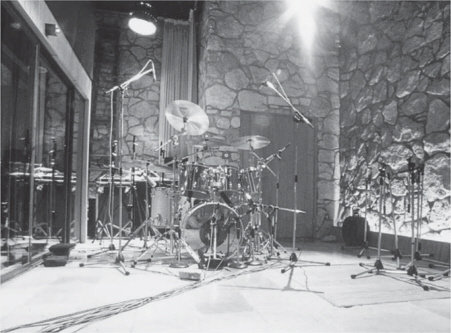
Figure 6.2 Townhouse Two, London (1978)
It is worth noting here that what directly led to the construction of the stone room in The Townhouse was that the first two recording engineers scheduled to work there, and its design co-ordinator (the author), had all had a lot of experience with mobile recordings. Many were made in old castles and country houses, especially for television programmes, and the crews were bringing the recordings back to the studios for mixing. ‘How do you get these sounds?’ was a common question from the staff of the studios, recognising that they were hearing things which were rarely encountered in studio recordings. Many people were beginning to recognise that a lot of interesting sounds could be recorded in spaces which were not purpose-designed studios.
It was thus not difficult, with the two senior engineers and the technical director all in favour of the idea, to persuade Richard Branson that Virgin should (as was quite normal for the company, anyway) take a bold step away from traditional studio design and put part of an old castle into The Townhouse. In fact, Virgin’s Manor Studio had a considerable amount of exposed stone in its main studio area after its re-build in 1975, so Virgin already had a halfprecedent. However, the stone room in The Townhouse was a bit of a shock to some recording staff when it was first built. For the first few months it was seen as a white elephant by many who tried to use it, because circumstances had led to the three main supporters of its construction working principally in Studio One, and not Studio Two where the stone room was sited. Finally, though, it only took one single highly successful recording to turn the room from a white elephant into a legend. It is interesting to contemplate what may have been the future of the room had Phil Collins not chosen to record his Face Value album in that particular studio. The life of the room could have been only a matter of months, instead of decades. Survival can hang on delicate threads.
6.6.1 Construction Options
One thing which most certainly can be said of stone rooms is that they are all different. In these days of pre-programmed instruments and factory set effects programs, stone rooms add an extra degree of variation. In effect, each studio owner has a genuine ‘first edition’, something unique, which, as experience of its performance is gained, can supply a sound unattainable elsewhere. As well as sizes and shapes, the type of stone can also be varied. The early rooms designed by the author were Oxfordshire sandstone, which was a little on the soft side and slightly crumbly. Consequently, a thin coat of polyurethane varnish was applied to reduce the dust problem. Subsequently, Purbeck and York stones were used, and later still, Spanish and Portuguese granites.
Granites allow a greater degree of variation in acoustics, and, being much harder, they have fewer tendencies to shed dust. Once a PVA adhesive has been added to bind the cement, the choice of varnishing the stone or leaving it bare introduces an interestingly different variable. Varnish noticeably softens the sound when compared to the natural granite, whereas with the softer stones, the varnish treatment is less readily noticeable. The high concentration of PVA adhesive in the cement, together with expanded metal backings to hold everything securely, allows the cement between the stones to be cut back, and thus exposes in a great deal of relief the outline of each individual stone. This technique was developed for the large drum room in Blackwing, London, initially as a cosmetic measure to produce a castle-like atmosphere, but its acoustic advantages also soon become clearly understood. The deep crevices between each stone gave a much more diffuse sound field, especially as the stones in that particular studio were laid in a highly random manner; again initially for cosmetic effect. The room is shown in Figure 6.3.
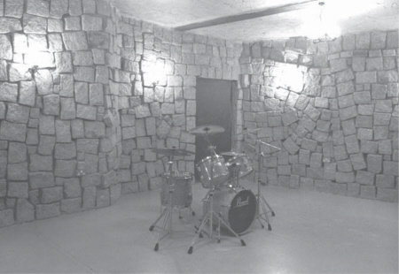
Figure 6.3 Splendid (Blackwing), London (1988)
One major problem which was solved in the design of the first Blackwing room was how to stop the low frequency build up, which had previously been problematical in rooms of that size and over. Blackwing was a large room by normal standards, 24 ft × 16 ft × 10 ft (8 m × 5 m × 3 m) after the internal finishes. The shell of the room was much higher, as the space had previously been used as a rehearsal room, with a mineral wool suspended ceiling. There was also a large amount of mineral wool, a metre deep, over this ceiling, and the aversion of everybody concerned towards being rained-on by such unpleasant substances during their removal concentrated minds wonderfully in the pursuit of alternative solutions. It was eventually elected to leave the ceiling in position, especially as, unusually for such ceilings, it sloped. A coat of bonding plaster, roughly applied, took advantage of that slope to produce a non-parallel, reflecting surface, opposing the concrete floor, with the roughness of the plaster helping the high frequency scattering.
The intention was to reflect mid and high frequencies back into the room whilst allowing the low frequencies to penetrate. For the low frequencies to be reflected back into the room they would have to penetrate the ceiling, suffer absorption by the metre or so of mineral wool overlay, reflect from the structural and isolation ceilings and return through the same obstacle course. Obviously, such a path would introduce severe attenuation of the low frequencies, so the ceiling would provide an escape path for them, and act as a high pass filter (from the point of view of the room response) in one of the three main axes of the room (the vertical axis). During the construction of this room there occurred a situation which is worth relating, because it sheds light on a rather important aspect of live room design in general.
On the day that the room was completed in all respects other than the plastering of the ceiling, it bought general disapproval from a number of people who had great expectations of its reverberation. The room with its concrete floor and granite walls was certainly bright, but no obvious reverberation existed. The studio owner had asked for a reverberant room that could double as an ‘echo chamber’. After the plasterer had done his work there was little change, nevertheless as the plaster slowly dried, little by little, the room came to life. The next day, with the plaster fully hardened and dry, the room delivered all that had been promised. This point will be returned to in Section 6.8, containing discussions about an empirically derived ‘20% rule’.
6.7 Live Versus Electronic Reverberation
Each stone room is unique, so it is difficult to say if one is better than another, or not. The knack of using them is to play to their individual strengths and to avoid their individual weaknesses. They add a degree of uniqueness to a studio which is simply not yet available with electronic devices; programmable, or not. There are some subliminal reasons for this, but there are also some very hard engineering reasons. Although low level effects in the tails of digital reverberator responses are generally very low indeed, we do often seem to detect them by their absence in natural reverberation tails. Some aspects of these decay differences have been difficult to measure, as we do not have analytical equipment even approaching the discriminative ability of the human ear/brain combination. What is more, many of the arguments about just what is, or is not, audible has been based on research into hearing thresholds relating to language and intelligibility. There have been many cases of people who have received accidental injuries resulting in severe impairment of their ability to communicate verbally, yet their appreciation of music has been unimpaired, implying that the areas of the brain responsible for the perception of speech and music are quite separate. Much more research is still required into these differences; however, there is no integrated signal reaching the brain which resembles an analogue of the eardrum motion. The ear presents the brain with many component factors of the ‘sound’, and it is only by way of a massive signal processing exercise by the brain that we hear what we hear.
It is the degree of these subtleties which still confound the manufacturers of digital reverberators. The late Michael Gerzon had studied in detail the then current state of electronic reverberators in the early 1990s. Michael was co-inventor of the SoundField microphone and the main developer of the Ambisonics surround sound system, and had much experience in the world of sound-field perception. He was also the first to propose dither noise shaping for digital audio, and was co-inventor of the Meridian Lossless Packing Audio data compression system, so his experience in the realms of both digital audio and spacial recording and perception were considerable. He said that the then state-of-the-art digital reverberation units, in electrical terms, represented something in the order of a ten thousand pole filter. The complexity of the inter-reaction of the sound field within a moderately sized live room, and the ability to simulate the directional and positional aspects of the microphones and loudspeakers, would need to be simulated by something in the order of a one hundred thousand million pole filter. Even if the current rate of acceleration of electronic development were to be maintained, it would be 40 years or so before a room could truly be simulated electronically; and even then, at what cost, and with what further restrictions?
A room simulator may well go a long way towards reconstructing the reflexion patterns for a sound emanating from one point in that phantom ‘room’. However, the nub of the issue is that in real life, a band, or even a drum kit, does not inhabit one point in space in the room. Different instruments, or different parts of one instrument, occupy different spaces in the room. Sounds are generated from very many different positions in the room, some at nodes, some at anti-nodes, and others at many points in-between. All excite different room resonances to differing degrees, and all produce reflexions in different directions. This subject was discussed in a previous section, and depicted in Figure 6.1. For example, the room behaves differently towards the snare drum than it does to a floor tom in the same kit. With current digital reverberation, all the instruments, and indeed all the individual parts of all the instruments, are injected into the phantom ‘room’ from, at most, only a few points in the theoretical space. All injections into the same space are driving a similar series of resonances; all are equally distanced from the rooms’ nodes and anti-nodes. Such occurrences do not exist in nature. What is more, in real rooms the microphones are also in different positions, so they all ‘hear’ the room in a different way.
Acoustic reverberation chambers, when driven by a large stereo pair of loudspeakers, can overcome this problem to some degree, but what any ‘after-the-event’ processing system lacks is the interaction between say, a drum kit, a live room in which it may be played, and a drummer. The drums excite the room, and the room resonances, in turn, interact with and modify the resonances of the kit. These processes undertake reiteration until energy levels fall below perceivable thresholds. The instrument, the room, and the musician are inextricably linked; they behave as one complex instrument. Physical separation of the playing and the addition of the reverberation break this very necessary unification. The room resonances modify the feel of a drum kit to the drummer, and the drummer will also perceive the room effects via any headphones, bone conduction, and general tactile sensations. The room will modify the musicians’ performance; and this cannot be accomplished after the event. Performances are unique events in time. It was on these grounds that the drummers rebelled against the mid-1970s, dead, high-separation drum booths which were then in vogue. It seems probable that electronic simulation will never have an answer for the human performance interaction problem, as no subsequently applied artificial reverberation can acoustically feed its effects back into the feel of the instruments themselves. Only artificial reverberation in the room itself, at the time of playing, could achieve that, which is one direction that the future may exploit.
Building stone rooms, or live rooms in general, is a very long way from the acoustic discipline of control room design. Control room design usually seeks neutrality in which the sound of the room is perceived to as small an extent as possible. For a control room to add any characteristic sound of its own is greatly frowned upon. Conversely, if a live room sounds good, then it is good. It is possible to walk away from a completed stone room with a degree of satisfaction, pleasure, excitement, and a sense of achievement in having created something different. Their only drawbacks would appear to be that they take up more space than a digital room simulation unit, they cannot be taken from studio to studio, and they cannot readily be traded-in or sold-off. People seem to expect to have all of their equipment encapsulated in boxes these days. Nevertheless, from this point of view, the stone rooms can comply . . . other than for the fact that they are not rack-mountable, they are somewhat large, and they tend to weigh in the order of twenty tons! An important point to be made here is that natural reverberation and artificial reverberation are two distinct things. They each have their uses, and sometimes either will suffice, but neither one totally replaces the other. Whilst sounds can be obtained from stone rooms that no artificial reverberator can match, it is equally true that electronic reverberators can produce some wonderful sounds that no live room could give.
6.8 The 20% Rule
The story of the ceiling at Blackwing, in London, in Section 6.6.1 highlights a point of general significance in terms of the percentages of room surfaces which are needed to create any significant effect. With the mineral wool ceiling it was difficult for the room to achieve any reverberation, as almost all of the energy in the oblique modes, which pass in a chain around all the surfaces of the room, would be absorbed upon coming into contact with the ceiling, and could thus never become resonant. In fact, even the energy in the tangential and axial modes would gradually expand into the ceiling. In the 8 m× 5 m × 3 m room, the total surface area is about 160 m2. The ceiling (8 m × 5m) has an area of 40m2, which is about 25% of the total.
A reverberant room generally needs to have reflective material on all of its surfaces, and usually, only about 20% of the total surface area needs to be made absorbent to effectively kill the reverberation. On the other hand, in a very dead room, introducing about 20% of reflective surfaces will usually begin to bring the room to life. Equally, a room with troublesome modal problems will usually experience a significant reduction of those problems by the covering of about 20% of its total surface area with diffusers. If one wall creates a problem, the covering of about 20% of that wall with diffusers will usually render the wall more neutral, but the diffusion should be reasonably evenly distributed over the surface to be treated.
At Blackwing it was absolutely fascinating to listen to the plaster dry, or rather to listen to the effect of its hardening on the room acoustics. The wet plaster was not very reflective, so upon initial application it did not significantly change the room, but once the hardening process began, after a few hours it was possible to witness an empty room changing very noticeably in its character, in a way which was almost unique. Without any physical disturbance or any abrupt changes, the room was ‘morphing’ from a bright, reflective room, to a highly reverberant one. The luxury of such experiences can provide much insight into the acoustical characteristics of rooms of this nature.
6.9 Reverberant Rooms and Bright Rooms – Reflexion and Diffusion
The terms brightness and reverberation often tend to get confused by the loose use of the term ‘live room’ when studio acoustics are discussed with many recording personnel. Stone rooms can be produced to either bright or reverberant specifications, and the flexibility is such that rooms looking very similar may sound very different. Figures 6.4, 6.5, 6.6 and 6.7 show rooms of very
different acoustic characters. All four are built with Iberian granite, and an explanation of the different construction techniques used in each case will help to give an understanding of the respective processes at work.
Clearly the reverberation which we are referring to in these rooms is not reverberation in its true acoustic sense. Reverberation refers to a totally diffuse sound-field, where its intensity and character is the same throughout the room. This cannot occur in small rooms as the existence of modal resonances and discrete reflexions will always ensure that places of different character can be found within the room. Even the absolute decay time of all reflective and resonant energy can be position dependent, but in general, the term reverberation as understood amongst most recording engineers is perhaps the most widely understood term which can be used in these descriptions. Certainly in the names of many programs in digital effects processors the term ‘reverb’ is now so universal that, except in academic acoustic circles, it would be like trying to swim up a waterfall to be too pedantic about its accurate use at this stage of the development of the recording industry. Bearing the terminological inexactitude in mind, let us look at some different ‘reverberant’ room designs.
In Figure 6.4, the room is about 5 m× 4m × 3m high, and is built using a facing of granite blocks, about 10 cm in thickness. The stones are bonded by cement to a studwork wall, which is covered in various sheet materials such as plasterboard, chipboard, and insulation board. The blocks have reasonably irregular surfaces, but are all laid flat against the wall. After the cement behind and between the block had dried, the gaps were pointed with a trowel, to smooth over the cement and bring it more or less level with the face of the blocks. The resulting wall is hard and relatively flat, but the irregularities are sufficiently large to be somewhat diffusive at frequencies above about 3 kHz. None of the walls are parallel, which helps to avoid the build-up of regular patterns in the axial modes. The ceiling is heavy, and of quite a solid structure behind the plaster. A fabric panel at one end of the ceiling covers the entrance to a low frequency absorber system, which helps to reduce excessive low frequency build-up. The room has two sliding glass doors, each about 1.8 m wide and 2 m high, one leading to the control room, and the other to the main recording space.
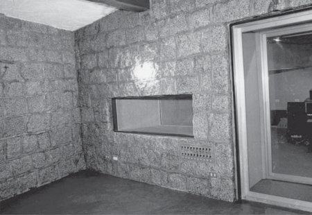
Figure 6.4 Planta Sonica, Vigo, Spain (1987)
The above room, at the former Planta Sonica studio in Vigo, Spain, produced some excellent recordings of drums, electric guitars, acoustic instruments, and especially the traditional Celtic bagpipes which are very popular in Galicia (the Celtic influenced province of Spain where Vigo is situated). The room decay was smooth, without excessive low frequencies, and spacially very rich sounding. The empty reverberation time was about 3 s, but of course the empty state is not really relevant in such cases, because it would not be used empty, except perhaps as a reverberation chamber during mixdown. In such cases, a loudspeaker/amplifier would be fed from the mixing console, and a stereo (usually) pair of microphones would pick up the room sound for addition to the mix. However, in normal use, the influx of people and equipment can have a great impact on the empty performance, as they tend to be absorbent and can occupy a significant portion of the total room volume.
The rooms in Figures 6.5 and 6.6 are built in a very similar manner to each other. Both have layers of granite covering the same sort of stud wall structure of Figure 6.4, but they are built more on the lines of Blackwing, as shown in Figure 6.3. Both also have the granite blocks laid in a more three-dimensional configuration, with many of the blocks protruding from the walls. They have somewhat similar types of ceiling structures, but are much smaller in size. The room shown in Figure 6.5 has a total surface area of about 90 m2, and the Figure 6.6 room about 60 m2. The room shown in Figure 6.6 also differs in being made from granite blocks having only a quarter of the surface area of those in the other rooms.
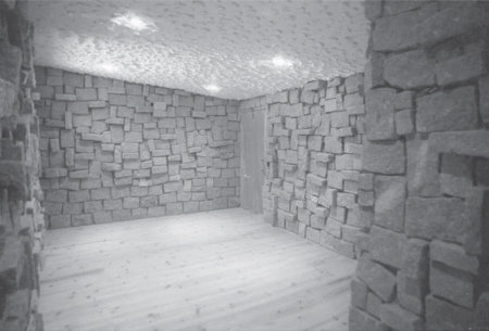
Figure 6.5 Discossete 3, Lisbon, Portugal (1991)
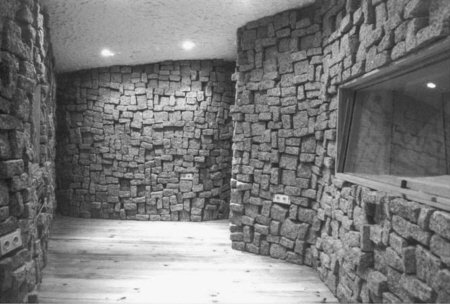
Figure 6.6 Regiestudio, Amadora, Portugal (1992)
The room in Figure 6.5 is a strongly reverberant room, but lacks the powerful reflexion patterns of the old Planta Sonica room shown in Figure 6.4. The deep cutting back of the cement between the blocks creates a series of randomly sized pits which render the surface much more diffusive, a property also enhanced by the protrusion of many of the blocks. Due to the non-parallel nature of the surfaces of the room, most of the energy will be concentrated in the tangential and oblique modes, thus the depth of the pits and protrusions is effectively increased because the modal incidence will be at varying angles to the wall surfaces, as shown diagramatically in Figure 6.8. The effect is that the walls are diffusive down to much lower frequencies than the walls of the room in Figure 6.4. There is therefore more diffusive energy in the decay tail than in the room of Figure 6.4. The more diffusive room does not produce the same haunting wail of bagpipes as the other rooms, but it can produce some very powerful sounds from congas, and rich enhancement of saxophones or woodwind. These two types of rooms are not really interchangeable; they are sonically very different.
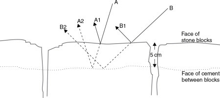
Figure 6.8 Effect of incidence angle on the reflexions from the pits and blocks. From a nominal depth of cavity of 5 cm, incident wave ‘A’ will travel about 10 cm further, before returning to the room, when it reflects from the back of the pits, as compared to when it reflects from the face of the blocks. Incident wave ‘B’, striking at a shallower angle, will show an even greater path length difference between the reflexions from the back of the pits and the reflexions from the faces of the blocks
6.9.1 Bright Rooms
Let us now move on to consider the room in Figure 6.6. This is a room with a total surface area of about 60 m2, about 4 m2 of which are non-parallel glass surfaces. There is also 2 m2 of flat, wood panelled door, and around 8 to 10 m2 each of wooden floor and sloping, highly irregular, plastered ceiling. The remaining surfaces of the walls, which form the majority of the surface of the room, are of small granite blocks, each having a face area of 80 to 100 cm2. The cement has been deeply cut back in the gaps, producing a series of irregular cavities, but unlike the rooms in Figures 6.2 to 6.5, the ratio of the surface area of the granite to the surface area of the pits is much less; in fact only around 20% of that in the other rooms.
The effect of this is to produce far fewer specular reflexions because there are fewer flat surfaces, at least not acoustically so, until much lower frequencies. Any wave striking the wall surface will be reflected differently from the stones and pits, but let us consider the case of what happens at 500 Hz, where the wavelength is around 60 cm. If the pits average 8 cm in depth, then a reflexion travelling from the face of the stones will travel about 16 cm less than when entering and being reflected from the back of a pit. This will create about a quarter-wavelength phase shift on a single bounce, and the irregular shape of the stones and pits will tend to scatter the wavefront as it reflects from the wall. At least down to around 500 Hz, such a room surface becomes very diffusive until specular reflexions begin again when the dimensions of the stone faces become proportionate to wavelength, say above 5kHz. However, at these frequencies and above, the irregularity of the stone surfaces themselves begin to become diffusive, so the walls do begin to scatter effectively from around 500 Hz upwards. There will also be a considerable degree of diffraction from the edges of the stone blocks, which will also add to the diffusion.
The room in Figure 6.6 is very bright, emphasising well the harmonics of plucked string instruments, and adding richness to flutes and woodwind. Somewhat surprisingly perhaps, the reverberation time is much shorter than one would tend to expect from looking at the photograph. In this type of room, which is also very small, the energy passes rapidly from surface to surface. As the surfaces are so diffusive, the scattering of the modal energy is very wide. Thus, in such a room, the number of times that a sound wave will strike a wall surface as it travels around is many times greater than would be the case in a room such as the one shown in Figure 6.3. Each impact with a wall surface, especially at a near grazing angle as opposed to a 90° impact, will take energy from the reflected wave, either by absorption (including low-frequency transmission), or by the energy losses due to the interaction of the diffusive elements. Consequently, in two rooms of any given surface material and construction, the small room will have the lower reverberation time because more surface contacts will take place in any given period of time. The smaller room will also have a higher initial reflexion density. The room in Figure 6.6 produces a brightness and thickness to the recorded sound, but it falls off within about one second.
Figure 6.7 shows a further variation on the theme, and is a room with a character somewhere between the ones shown in Figures 6.4 to 6.6. It is the only recording space of a small studio, so it has to be slightly more flexible than the ‘specific’ rooms shown in the other photographs. When empty, it has a reverberation time of just over 2 s, but this can readily be reduced by the insertion of lightweight absorbent ‘pillars’ containing a fibrous filling, especially when they are positioned some way out from the corners. As was discussed in Chapter 4, fibrous absorbers are velocity dependent, so they should not be placed too near to a reflective surface or their effect will be reduced.
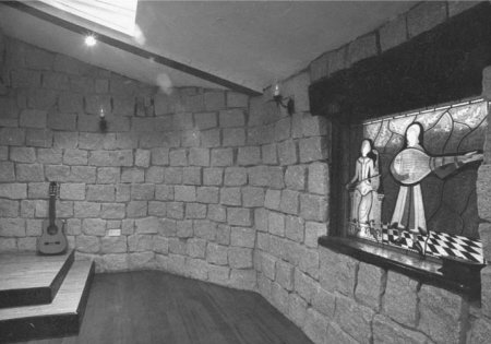
Figure 6.7 Shambles, Marlow, England (1989)
From the descriptions of the rooms shown in Figures 6.2 to 6.7 it can be appreciated that the cutting back of the cement to form pits between the stone blocks both increases the diffusion and lowers the decay time. Figures 6.8 and 6.9 will help to show the mechanisms which create these effects. Figure 6.8 shows the way in which the reflexion paths differ from the front of the blocks and the back of the pits. It can also be seen that for angles of incidence other than 90°, the disruptive effect will be greater as the path length differences increase. The frequency dependence of the effect of the irregularities is shown in Figure 6.9. At 400 Hz there is little difference in the interference patterns created when a plane wave strikes either the flat surface or the irregular surface at a 90° incidence angle. At 1600 Hz, however, the reflected wave is well broken by the 10 cm depth of surface irregularity. It can also be seen that the energy in the pattern reduces significantly more rapidly further away from the wall, which is a result of the diffusive effect.
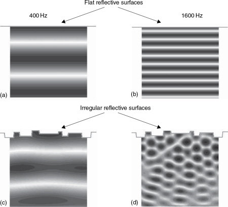
Figure 6.9 Effect of surface irregularities on reflexion patterns. Figures (a) and (b) show the interference patterns of 400 Hz and 1600 Hz plane waves when reflecting from a flat surface. Figures (c) and (d) are again 400 Hz and 1600 Hz plane waves, but this time the interference fields are those produced by reflexions from an irregular surface, such as a rough stone wall. In (c) the 400 Hz pattern is little changed from (a), but at higher frequencies, as shown in (d), where the size of the irregularities becomes significant in proportion to the wavelength, the reflexion pattern becomes fragmented, and loses energy more rapidly after reflexion
In normal situations the effect is even more pronounced than that shown in Figure 6.9, because the rooms which employ such techniques usually have non-parallel surfaces. This tends to cause more of the sound waves to strike the wall surfaces at angles of incidence other than 90 degrees, where the path length differences caused by the irregularities will be greater. The two primary effects of this are that the disturbance of the interference field will extend to lower frequencies and the energy losses after reflexion and diffraction will be greater.
Section 5.4 looked at the question ‘What is parallel?’ and showed that the degree to which a pair of surfaces was acoustically parallel was very frequency dependent. Somewhat similarly, Figure 6.9 shows the highly frequency-dependent nature of the effect of surface irregularities. At 1600 Hz, the effect of the surface irregularities can clearly be seen (and heard). At 400 Hz, the effect of the surface irregularities is only minimal in comparison to the interference pattern produced by an absolutely flat wall. Down at 50 Hz the effect of the surface irregularities such as those shown in Figures 6.8 and 6.9 would be non-existent. So, in acoustical terms, a surface which can be highly non-uniform at 1600 Hz can be seen to be absolutely regular at 50 Hz.
6.10 Low Frequency Considerations in Live Rooms
As discussed earlier in reference to the large room at Blackwing (Figure 6.3), all 24 m2 of the ceiling was used as a low frequency absorber. Yet even with this amount of absorption the low frequency reverberation time is still much greater than that of the other rooms mentioned, principally due to its larger size. (See Equation 4.7.) Without such an absorber, the room would have produced a build-up of low frequency energy which would have muddied all the recordings, and much definition would have been lost. No such absorption was needed in the room shown in Figure 6.6 because a similar low frequency build-up cannot develop in rooms of such small dimensions. The modal path-lengths are too short to support long wavelength resonances. We shall consider this point further in the following section.
Figure 6.10 shows the way in which the characters of rooms are controlled by the different acoustical properties of their dimensions and surfaces. At the high frequencies, the room response is generally controlled by the relationship of specular reflexions to absorption. Effectively, here, the sound can be considered to travel in rays, like beams of light. In the mid-frequency band, control is mainly down to the diffusion and diffraction created by the irregularities and edges of the surfaces. At the low and lower-mid frequencies, the room response is mainly that which can be reinforced by modal energy. This region is usually dealt with in terms of normal wave-acoustics, but as the room size reduces, it tends to produce a greater spacing of modal frequencies, hence the energy is concentrated in more clearly defined frequency bands, which leads to a more ‘coloured’ or resonant sound characteristic. As the room dimensions are reduced, however, the lowest modal frequencies which can be supported are driven upwards, so excessive low frequency build-up becomes less likely.
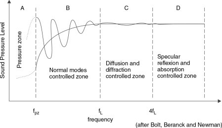
Figure 6.10 Controllers for steady-state room acoustics. The above diagram shows the frequency ranges over which different aspects of room acoustics are the predominant controllers. Explanations of fpz and fL are given in the text. In the pressure zone, the response of a loudspeaker is not supported by room effects, so loudspeakers driving the pressure zone may need to be capable of considerable low frequency output
Small rooms tend to sound ‘boxy’ because the modal energy is in a higher frequency range, reminiscent of the sound character of a large box, hence the ‘boxy’ sound. The modally controlled frequency region is bounded in its upper range by a limit known as the large-room frequency, and at its lower range by the pressure zone, as previously discussed in Section 5.8.3. (The pressure zone is also discussed further in Section 13.5.) In Figure 6.11(a), a sound wave can be represented by a line crossing the room. This is a snapshot in time, and shows the positions of high and low pressure for that instant. For a travelling wave (i.e. not a resonant modal path) another snapshot taken a few moments later would show the peaks and troughs uniformly shifted in the direction of travel. At resonance, however, the interference pattern of the direct and reflected waves becomes fixed in space. A resonance occurs when the distance between two opposing, reflective surfaces bears an exact relationship to the wavelength of the resonant frequency, and a stationary wave results.
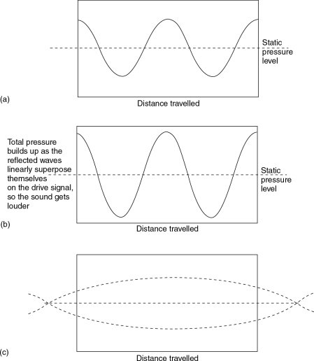
Figure 6.11 The pressure zone. (a) A wave traversing a room will produce areas of high and low pressure that correspond to the compression and rarefaction half-cycles of the wave. Upon striking the opposing wall, it will reflect back, and, if the path length is an integral multiple of the wavelength, the returning reflexions will be exactly in phase with the drive signal. (b) As the drive signal continues, it will add in-phase energy to the resonant energy, which will build up the total energy in the resonant mode. This is similar to the effect of adding energy at the right moment to a child on a swing, when the arc of swing can be made to increase with little effort. (c) Where the wavelength is longer than twice the size of the room, the whole room will be rising or falling in pressure, more or less simultaneously. This is the pressure zone condition, where alternate regions of high and low pressure are not evident. No resonances can therefore occur in this region
The resonant modal pathway tends to trap the energy, with the peaks and troughs of the direct and reflected waves exactly coinciding with each other. The energy build-up in such circumstances can be very great. The effect is analogous to a child on a swing. If the start of the energy input to the swing (a push) is timed to coincide with the peak of its travel, the swing can build up great oscillations with what appear to be only minimal inputs of applied force. (See Figure 6.11(b).) However, Figure 6.11(c) shows that when wavelengths become sufficiently long, there are no noticeable alternate regions of the room with above and below average pressure, but rather the whole volume of the room is simultaneously either rising or falling in pressure. The room response is thus unable to boost the initial sound wave by adding any resonant energy, because it cannot provide any resonant pathways, and the sound thus decays rapidly. This is one reason why the low frequency reverberation response of rooms falls as room size reduces, as well as, of course, the energy losses due to the increased number of wall impacts per second. Conversely, in large halls, where the pressure zone frequency is in the infrasonic region, even the lowest audible frequencies can be reinforced by modal energy. These frequencies are notoriously difficult to absorb, and are not significantly lost through doors or windows unless these are proportional to their wavelengths. They also largely refuse to be thrown from their paths by obstructions, unless they are of sizes in the region of a quarter of a wavelength of the frequencies in question. In the smaller rooms, however, when the pressure zone frequency rises into the audible spectrum, added to the increased losses due to the greater number of wall strikes per unit of time, it is therefore to be expected that the low frequency reverberation time will tend to fall off more rapidly than in larger rooms.
The large-room frequency, bounding the frequency region dominated by normal modal energy and an upper frequency range which is mainly diffusion/diffraction controlled, can be estimated from the simple equation given by Schroeder:
| (6.1) |
where
FL = large-room frequency (Hz)
K = constant: 2000 (SI)
V = room volume (m3)
RT60 = apparent reverberation time for 60 dB decay (seconds)
6.11 General Comments on Live Rooms
The rooms depicted in Figures 6.3–6.7 all have very different sonic charac teristics which are derived from their physical sizes, shapes, and the nature of the arrangement of their surface materials. This is despite the fact that, except for their floor surfaces, they are basically all constructed from the same materials. In these cases, the floor material was of relatively little overall significance, although stone floors, perhaps, would add just a little extra brightness. Rooms such as the ones described here, as with all live rooms, take some time to get to know, but once known they can be very acoustically productive. They also take a great deal of experience to design and construct. Bad ones can be really useless, or of such restricted use that they are more of a liability than an asset. There is no current hope of computer modelling these rooms, partly because the complexities of the interactions are enormous, and also because the influence of complex room shapes on the acoustical virtues of the subjective perception are not yet sufficiently understood to program them into a computer. The influence of the great variety of equipment and people who may ‘invade’ the acoustic space is also beyond current modelling capability. However, for engineers wishing to record in such rooms, hopefully this discussion will have provided enough insight to make the process more productive.
Orchestral music was designed to be performed live in front of an audience. When many of the great classical works were written there was no such thing as recording, so the instrumentation and structure of the music was aimed only at its performance in spaces with audiences. Transferring the performance into a studio, perhaps of only just sufficient size to fit the whole orchestra, imposes a completely different set of conditions. As was discussed in Section 6.3, a big constraint on the achievement of a natural orchestral sound in studios is the fact that the whole process is usually entombed in a massive acoustic containment shell. This even further removes the ambience of the studios from that of the concert halls.
Today, much orchestral recording is for the soundtracks of films, and in such circumstances, when the conductors need to see the films as well as to be in close contact with the musicians, the facilities of a studio are more or less mandatory. Nevertheless, (under less technically demanding circumstances) ever since the earliest days of recording a large proportion of orchestral recordings have been made outside of purpose-built studios. When one begins to consider the deeper element of achieving good orchestral recordings, the above fact comes as no surprise.
6.12.1 Choice of Venues, and Musicians’ Needs
Around the world there are some very famous and widely-used locations for orchestral recording. Not too surprisingly, concert halls are one member of this group, but assembly halls, churches and cathedrals are also popular locations. One requirement of such a space is that it needs to be big enough to house the orchestra, but usually, the apparent acoustic space needs to be even larger.
If we first consider the obvious, recording in a concert hall, there are two conditions likely to be encountered; recording with, or recording without an audience. Performances intended for recording tend to be assessed in greater detail than live performances. A small defect which may pass in a live performance may be irritating on repeated listening to a recording. The straightening out of these small points can become very time consuming. Frank and open discussion of these points would rarely be possible in front of an audience, nor would such occurrences be likely to constitute an interesting spectacle for the paying public, so almost out of necessity, many such recordings take place out of public view. Unfortunately, if such recordings are made in a concert hall, then that hall will probably have been designed to have an appropriate reverberation time when full. Its empty acoustic may not have been a prime object of its design; although in an attempt to make the acoustics independent of audience numbers, some halls have seats with absorption coefficients which, even when empty, try to match that of an occupied seat.
With recording techniques using close microphones this may or may not be of great importance, but for recordings with more distant microphones the ambience of some empty halls may be undesirable. Surprising as it may seem, even when full, not all concert halls are highly rated for orchestral recording purposes. A concert hall is an expensive thing to build, and few can be dedicated solely to orchestral performances. Consequently, ideal orchestral acoustics may have to be compromised to accommodate other uses of the halls, such as for conferences, operas, ballets, electrified music concerts or jazz performances. Each use has its optimum set of acoustic conditions, both in terms of hall acoustics and stage acoustics. Furthermore, in addition to the optimum reverberation requirements, lateral reflexion characteristics may also form another subdivision of the ideal acoustics for each use.
Some of the old halls, built before recording existed, are still very well liked. In fact, this is not too surprising, for they frequently did not have to make quite so many performance compromises as for halls of more recent construction. Moreover, when much of the classical music repertoire was written, it was written with many such concert halls in mind. The fact that much classical music can be expected to sound good in those halls is something of a self-fulfilling prophesy. Acoustic live performances were the only performances to be heard by the public when those halls were built, and no compromises needed to be made to allow for electric amplification. Many orchestral pieces were even written with specific concert halls already considered for their first public performances. However, this is somewhat akin to writing and recording a piece of music in a studio with idiosyncratic monitoring: it may not easily transfer to more acoustically neutral surroundings.
The great composers usually also had a comprehensive understanding of the needs of the musicians: because they were musicians. Orchestral musicians need to hear themselves in a way that is both clear and sonorously inspiring. They also need to hear, clearly, many of the other musicians in order to develop the feel of the performance. Composers often bore these facts in mind when arranging the instrumentation, so the music, the instruments themselves and the halls in which they frequently performed developed not in isolation, but in concert with each other. It is thus not surprising that many of the shoe-box shaped halls, which have been common-place for centuries, are still well liked by musicians, recording personnel, and audiences alike.
In recent years it has become apparent that, for a rich sense of spaciousness, lateral reflexions are of great importance. The shoebox shaped designs provide plenty of these, but they can be very problematical for many other purposes for which the hall may be used, often wreaking havoc, for example, with the intelligibility of the spoken word. Conferences or speeches in such halls can be difficult. In fact, the reason why so many religious masses are chanted, and not spoken, is because the longer sounds of a chant are less easily confused by the reflexions and reverberations of most churches than would be the more impulsive consonants of normal speech. Hard consonants would tend to excite more modal resonances, as they contain more frequencies than the softer chanted consonants. Ecclesiastical chanting therefore appears to have been of acoustic origins rather than religious ones.2
Nowadays, however, we must perform much of the old music in the multi-functional halls, or in churches, town halls and the like. What all of these locations have in common though, which sets them aside from most recording studios, is the large amount of space which they have for the audiences or congregations. They also tend to have many windows and doors, which allow an acoustic coupling of the internal spaces to the outside world. They are not constrained within the bunker structure of a sound isolation shell, and all, therefore, have room to ‘breathe’ at low frequencies; even if this is not immediately visually apparent from the interior dimensions of the rooms themselves. Given this acoustic coupling through the structure, they tend to appear to be acoustically larger than they are physically.
6.13 RT Considerations
The optimum reverberation time (RT) for orchestral recordings tends to vary, according to the music and instrumentation, from about 1.6 to 2.5 s in the mid-band, with the 5 kHz RT usually being around 1.5 s. The low frequency RT is a continuing controversy, with differences of opinion as to whether the 100 Hz RT should rise or not, and if so, by how much. In general, there are compromises with different reverberation times between definition, warmth, and majesty. Inevitably the optimum requirements for each piece of music, or each orchestral arrangement, will call for somewhat different conditions, as will the presence or absence of an organ, chorus, solo piano, or number of contrabasses in the orchestra. There is a general tendency to believe that a moderate rise in RT at low frequencies is usually desirable, but that introduces yet another variable; personal preference.
The contours of equal loudness could have something to do with the LF debate. Figure 2.1 shows the classic Fletcher–Munson curves alongside the more modern equivalent, the Robinson–Dadson curves. The latter are now generally accepted as being more accurate, but the differences are too small to have eclipsed the former in general usage, so both sets of curves are shown for comparison. What they both show is how the sensitivity of the ear falls at the extremes of the frequency range. If the 0 phon threshold line at 3 kHz is followed to 30 Hz, it strikes the sound pressure level line at 60 dB. If the line passing through the 25 phon point at 3 kHz is followed down to 30 Hz, it will be seen to pass through the SPL line at around 65 dB. These are curves of equal loudness, and the above observations mean two things. Firstly that 60 dB more (or one million times the acoustic power) is needed at 30 Hz to reach the threshold of audibility than is needed at 3 kHz. An extra 40 dB (or 10,000 times the power) is needed at 30 Hz to sound as loud as a tone of 25 dB SPL at 3 kHz. So, it can be seen that the ear is vastly more sensitive to mid-frequencies than to low frequencies at low sound pressure levels. Secondly, the rise of 25 dB in loudness from 0 dB SPL to 25 dB SPL at 3 kHz needs only a 10 dB increase at 30 Hz to produce the same subjective loudness increase.
Looking at these figures again, 25 dB above the threshold of hearing at 3 kHz (the 30 phon curve) will sound as loud as only 9 or 10 dB above the threshold of hearing at 30 Hz. The perceived dynamics are considerably expanded at the low frequencies. At high SPLs, above 100 dB, the responses are flatter. Let us consider a symphony orchestra in a hall, playing at 100 dB SPL. The direct sound will, according to the 100 phon lines on the equal loudness curves, be perceived in a reasonably even frequency balance. However, when the reverberant tail has reduced by 50 dB, and is still very clearly audible at 50 dB SPL in the mid-range, the lower octaves will have fallen below the threshold of audibility.
Considering the fact that much of the reverberation that we perceive in concert halls is that of the tails, after the effect of the direct and reflected sounds has ceased, then much of our perception of that reverberation will be in the area where the low frequencies would be passing below audibility if a uniform reverberation time/frequency response existed. This suggests that halls with a rising low frequency reverberation time may be preferable for music which is performed at lower levels, in order to maintain a more evenly perceived frequency balance in the reverberation tails. Rock music, on the other hand, played at 120 dB SPL, may well degenerate into an incomprehensible confusion of low frequency wash in halls in which the RT rises at low frequencies. In fact, electrified rock music usually requires a much lower overall RT than orchestral music, and, quite definitely for rock music, a flatter RT/ frequency ‘curve’ is desirable, or even one where the low frequency RT falls.
6.14 Fixed Studio Environments
As has probably already been gathered from all of this, to produce a large single recording studio to mimic all of these possibilities would be a mighty task indeed. It is one very significant reason why so many orchestral recordings are done in the aforementioned wide range of out-of-studio locations.
Live performances inevitably must be recorded in public halls, though the reasons for recording live are not always solely for the hall acoustics. It can be very difficult to lift the definitive performances out of orchestras in studios. The adrenaline of a live performance will, in most cases, give the recording an ‘edge’ which the studio recordings frequently fail to achieve. Nevertheless it is still heard from musicians that far too many studios also fail to inspire a performance from an ambient point of view. All too often, the ‘technical’ environment of many studios is not conducive to the ‘artistic’ feel of a hall. Comfort and familiarity with the surroundings can be a very important influence on musicians, as can their own perception of their sound(s). In most concert halls, assembly halls, and other such places used for recording, the performing area is usually surrounded on at least three sides by reflective surfaces. As mentioned before, these lateral reflexions are of great importance to the sense of space, and by association, with the sense of occasion. If the acoustic conditions in a studio can help to evoke the sense of the occasion of a concert stage, then that studio may well be off to a good start in terms of the comfort factor for the musicians.
The one big obstacle in re-creating realistic performance space acoustics in a studio is the normal lack of the open space in front of the orchestra. During concerts, the musicians face from the platform into a hall, from which there will probably be no significant reflexions, but much reverberation. The musicians thus receive the bulk of their reflexions from the stage (platform) area, and the subsequent reverberation from the hall in front of them. Human hearing is very directional in the horizontal plane, so the perception of the necessary reflexions, which help to reinforce and localise the instruments, can be easily discriminated from the equally necessary reverberation. The reverberation usually does not swamp the reflexions because of the spacial separation of the two.
In a studio of practical size we have a great problem in trying to recreate this situation. If the orchestra faces a reflective wall, the reverberation will be confined within the area of the performance, and additional reflexions will also arrive from the front wall. If we make the wall absorbent, we will tend to kill the overall reverberation. Either result is unnatural for the orchestra. It would seem that perhaps the only way to overcome this would be with a relatively absorbent wall containing an array of loudspeakers, coupled to a programmable artificial reverberation system. This way a reasonably sized studio could be created, say about the size of a concert platform, but with the effect of a reverberant hall in front of the musicians. The directional characteristics of the sound could thus be preserved whilst keeping the studio to a reasonable size. A diffusive front wall could be another option.
It is doubtless the directional sensitivity of our hearing which is at the root of the phenomenon that when using conventional microphones (SoundField microphones can be an exception to this) the necessary microphone position for a subjectively most similar direct/reflective/reverberant balance is usually considerably closer to the orchestra than would be the corresponding seating position for a listener. However, it must be said that the microphone positions are usually above the audience, so they perhaps suffer less from local absorption by the seating, but this does not account for all of the effect.
What tends to set orchestral studios apart from most other studios is that a generally rectangular acoustic shape is rather more common, a typical example of which is shown in Figure 6.12. Walls are normally faced with a significant amount of diffusive objects to break up unwanted cross-modes, but the more or less parallel-sided nature can help greatly in the reproduction of the environment of the platform of a hall. Ceilings, though, as in halls, are almost never parallel to the floors. In some multi-functional rooms, they may be found to be parallel, but they are most likely to be relatively absorbent. Many concert halls have acoustic reflectors above the platform, usually angled to project more of the sound towards the audience, though frequently the sound also rises into scenery and curtain raising mechanisms which can be quite absorbent in their overall effect.
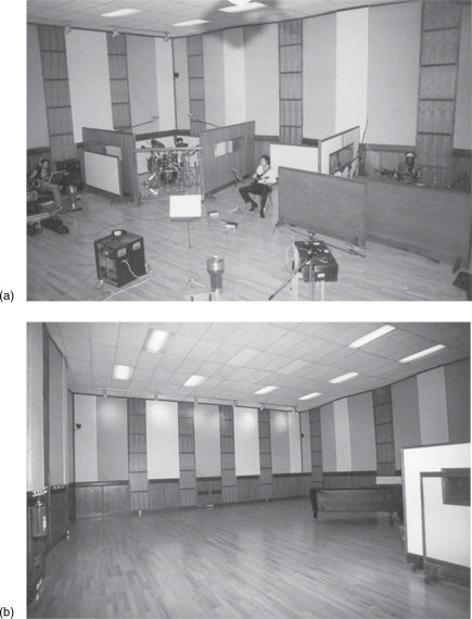
Figure 6.12 Namouche studios, Lisbon, Portugal (1994)
Figure 6.13 shows a studio designed for a wide range of recordings, including medium-sized orchestras. It is designed with a shape reminiscent of many concert platforms, and is surrounded on three sides by walls of wood and glass panelling. The wall adjacent to the control room, which would normally be facing the orchestra, is very absorbent, although some energy, quite well diffused, will return from the control room window. The lateral walls are fitted with rotating triangular panels of a type shown in Chapter 7, Figure 7.9(a). These panels are mounted in front of wood panelled walls, and have absorptive, diffusive and reflective (flat) sides. The ceiling has a mix of diffusive, absorptive and reflective properties. The design brief was to construct an orchestral concert platform but with acoustics sufficiently variable to allow a wide range of recordings. A live room (stone), a dead room, and a well-controlled vocal room are sited behind the various glass doors.
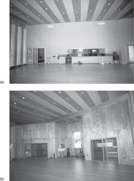
Figure 6.13 Estudios MB, Canelas, Portugal (2001)
However, in no cases can studio acoustics be separated from the controversy on the subject of the use of close versus distant microphones. Many people, when listening to recorded music, enjoy the dynamism of the close mic’d recordings, yet often they also can equally enjoy the more integrated grandeur when listening to many of the ‘stereo pair’, distant microphone, or Sound-Field recordings. The problem is, of course, that a listener at a live concert cannot be both near and far from the orchestra at the same time. With microphones, via a recording, it is possible, but to the ears of many people the result is perceptually confusing unless either one is greatly subservient to the other, and present only for added detail or richness. The problems of which option to take usually revolve around the fundamental aspects of psychoacoustic perception, some of which are mutually exclusive. Essentially, close and distant microphone techniques are two entirely different things, and the use of either is a matter of choice. They are not in competition for supremacy, but are merely options for the producers, who will choose the techniques which are considered to be appropriate for any given occasion. However, insufficiently flexible studio acoustics may force the decision one way or another, irrespective of which one would have been the more ideal artistic choice.
6.15 Psychoacoustic Considerations and Spacial Awareness
Not all of the problems of the design of recording studios for orchestral use are of direct concern to the recording engineers. Many other things which affect only the comfort and sense of ease of the musicians must be taken into account if the best overall performances are to be recorded. Sometimes these things can be better explained by looking at extreme situations, which help to separate any individual characteristics which may only be subconsciously or subliminally perceived in the general confusion of the recording spaces. So, let us now take a look at some of the spacial effects which can play such great parts in the fields of awareness and comfort.
Let us consider the Anglican Cathedral in Liverpool, UK. Its pipe organ was originally commissioned in 1912 as the largest and most complete organ in the world. It has 145 speaking stops, over 30 couplers, around 9,700 pipes, and on Full Organ can produce a 120 dB SPL in the 9 s reverberation time of the cathedral. It is blown by almost 50 horsepower of blower, and it needs it all because the cathedral is one of the ten largest enclosed spaces in the world. Its size is truly awe-inspiring.
When inside the cathedral, one is aware of a reverberant confusion from a multitude of noise sources, but occasionally, on windless days and when not open to the public, there are occasions of eerie silence. When speaking in a low-to-normal voice to a person close by in the centre of the great nave, it is almost as though one is speaking outside in a quiet car park. It is not anechoic, as there is a floor reflexion to liven things up, but the distances to the other reflective surfaces are so great that by the time they have returned to the speaker they are below the threshold of audibility. However, a sharp tap on the floor with the heel of ones shoe is followed almost half a second later by an explosion of reverberation, lasting eight seconds or more. The clarity of the initial sound is absolute, as coming from the floor it has no floor reflexion component; yet a subsequent tap, originating before the reverberation of the first one has died down, is almost lost in the ambient sound. This highlights well the temporal separation discrimination which plays so much part in orchestral acoustics.
In the early 1980s, Hugo Zuccarelli, the Argentinian/Italian ‘Holophonics’ creator, visited many recording studios in the UK and elsewhere, demonstrating his new spacial recording system. On headphones at least, he could pan things around the head with stunning realism; and realism not only of position, but of clarity as well. He also had a demonstration cassette of rather poor quality, yet the sounds of jangling keys remained crystal clear in front or behind the head, whilst the tape hiss remained fixed between the ears. It was impressive because the wanted sounds became absolutely separated from the noise, existing totally naturally and noise-free in their own spaces. This demonstrated most clearly the powerful ability of the ear to discriminate spacially, even in what amounts to an entirely artificial environment. The Holophonics signal supplied equalised, phase/time-adjusted signals to the ears, not present in mono signals, or necessarily in multiple microphone stereo recordings. The extra information provides a powerful means for the brain to discriminate between different signals, including between the wanted and unwanted sounds.
The old chestnut of ‘The Cocktail Party Effect’ has been around for years, and is no doubt already familiar to most readers. To recapitulate, if a stereo pair of microphones is placed above a cocktail party and auditioned on a pair of headphones, but panned into mono, then the general murmur of the party would be heard. However, it would be difficult to concentrate on any individual conversation, unless one of them happened to be occurring very close to the microphones. When auditioned in stereo, on the other hand, at exactly the same level, suddenly it would become clear that many separate conversations could be easily recognised and understood. The precise audiological/psychoacoustical mechanisms behind this have still not been fully explained, but nonetheless the effect itself is very well established as fact.
If we lower the level of the cocktail party recording into the domain of the stereo background noise of the tape hiss, then the conversations will begin to get lost in it, masked by the hiss even whilst still relatively well above the absolute hiss level. But this is not the case with the effect of Holophonics, which can lift a recognisable pattern out of the hiss by spacial differentiation beyond the in-head localisation of conventional headphone stereo. The phenomenon, once recognised, has a lasting effect. The significant difference between the effects of Holophonics and conventional stereo is that conventional stereo only provides information in a single plane, the Holophonics effect is three dimensional. The single plane of conventional stereo contains all the information, both wanted and unwanted, so the tape hiss shares the same sound stage as the wanted signals: they are all superimposed spacially. In Holophonics, however, the wanted signals can be positioned three-dimensionally, yet the tape hiss is still restricted to its single plane distribution. Once sounds are positioned away from the hiss plane they exist with a clarity which is quite startling, and it is remarkable how the hiss can be ignored, even at relatively high levels, once it is spacially separated from the desired signals.
Thus, we have several distinct mechanisms working in our perception of the spaces that we are in, and all of the available mechanisms are available to the musicians in their perceptions of the spaces in which they are performing. Clearly, all of these mechanisms cannot be detected by microphones, nor can they be conveyed to the recording medium, and consequently many of them will never be heard by the recording engineers in the control rooms. In fact, although the recording engineers may well, consciously or subconsciously, perceive these things, they often fail to fully realise their importance to the musicians. To the musicians, however, who work with and live off these things daily, their importance cannot be over-stressed. In the recording room, therefore, all of these aspects of the traditional performance spaces need to be considered. Quite simply, if the musicians are not at ease with their environment, then an inspired performance cannot be expected.
From time-to-time, there are situations which require even orchestral musicians to wear headphones when recording; either full stereo headphones or single headphones on one ear. However, perhaps the major reason why this is usually avoided is not the enormous number of headphones required, but that inside headphones, certainly if they are of the closed type it is not possible to reproduce the type of complex sound-field that the orchestral musicians are accustomed to playing within. Human aural pattern recognition ability is very strong, often even when sounds are hidden deep within other sounds, and even deep in noise. If headphones isolate the musicians from the usual patterns, the effect can be very off-putting.
For many of the reasons discussed, orchestral studios should not be designed primarily for what is good from the point of view of the recording personnel. First and foremost a performing environment should be created to aid the whole recording process. There are some hi-fi fanatics who would disagree, but most people would rather hear a compromised recording of an excellent performance, than an excellent recording of a compromised performance. Obviously, though, the real aim of the exercise is to make excellent recordings of excellent performances, and this is why so many things must be considered.
Many musicians of all kinds play off their own sound; it is like a feedback mechanism that both reassures and inspires them. This is true of more or less every musician and of whatever type of music that they perform. If their sounds are not given to them in their foldback as they need, then it can be very disconcerting. In the case of orchestral musicians, their foldback is not usually via headphones, but via the reflective surfaces of the room. Somewhat confusingly the orchestral musicians often refer to it as feedback. If playing to a backing track, it will possibly be only the conductor who will listen to it on headphones. In these cases, the acoustic of the performing space provides the foldback (feedback) to the musicians, so it should be given its due consideration as such.
Another frequent conflict between the needs of musicians and those of the recording engineers is the use of acoustic screens. In the close microphone type of recording, separation is a factor which is often considered desirable by the engineers. This can be improved by the use of acoustic screens between different sections of instruments, which normally as a concession to the musicians have windows to allow eye-to-eye contact. Unfortunately, this can disrupt the perception of the desired acoustic sound-field by the musicians, and in most cases they would prefer the screens not to be there.
It has been quite amazing how, over the course of recording history, musicians needs have so often been neglected in the recording process. Time and time again, if the recording engineer has had a problem with overspill, screens have been imposed upon the musicians, without due consideration of the effects of their insertion on other aspects of the recording process. In many cases recording staff have totally failed to appreciate the artistic damage which can be done by delays and disturbances caused by technical adjustments. Awareness of such things has been one thing which has set apart the specialist recording engineers and producers, who by understanding things in a more holistic way have gained the cooperation and respect of the musicians, and have thus produced more inspired recordings from which they have deservedly built their reputations.
This discussion on some rather peripheral aspects of audiology and psychoacoustics has not been a digression, but is a fundamental requirement in understanding what is necessary for the design of good recording spaces for orchestral performances (or perhaps rather, for the design of good performance spaces in which orchestras may be recorded). What must have become evident from the discussion is that acoustic variability is a prime consideration in any such design, unless the space is to be restricted to excelling in the recording of perhaps only a small range of the likely performances for which it may be required.
The room variability needs to be in terms of overall reverberation time, and if possible, the relative balance of low and mid/high frequency reverberation. Reflexions need to be controllable in terms of time, direction, and density, with the availability of some reasonably diffusive surfaces to add richness without undue colour. Always, however, the consideration of what the musicians need should be given at least equal weight to the needs of the recording staff when acoustic adjustments are being made. It is very necessary to strike a balance between these priorities and to achieve the close cooperation between all parties involved. Hopefully, what this chapter has shown is that whilst rooms of strong characteristic acoustics can be very valuable and even insuperable when their specific strengths are precisely what are required, they can also be very inflexible. This can lead to their use being limited, and when space is at a premium, something capable of a wider range of acoustic options is more desirable. The following chapter will therefore look at means of creating rooms with highly variable acoustics.
6.16 Dead Rooms
Before leaving the subject of specialised recording rooms, perhaps we should look at the design of a very dead room. Indeed, one such room exists in each of the studios shown in Figures 6.13, 7.1 and 8.2. They can produce interesting sounds when used as isolation rooms for bass guitar amplifiers, and quite a number of vocalists have been noted as liking the ‘different’ sounds which recording in such rooms can achieve. Figure 6.14 shows two cross-sections of such a room. The ceiling, above 2.5 m, consists of a series of hanging panels of plywood, spaced about 30 cm apart and lined on each side by 4 or 5 cm of 40 kg/m3 fibrous material. One wall is treated with a layer of 60 cm thickness of 40 kg/m3 mineral wool. The other walls are constructed as shown in Figure 5.1.
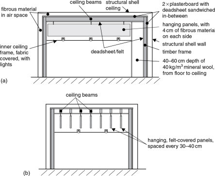
Figure 6.14 The construction of a dead room. (a) Side elevation, (b) end elevation
The floor is hard and the glass doors are useful for good visibility if the musician is in the room, and not playing via a remote amplifier head. Nevertheless the same conditions apply as were discussed about the room shown in Figure 5.19, whereby the directionality of the microphones can be used to avoid picking up any undesirable reflexions. In the cases of bass amplifiers facing the super absorbent wall, the microphone would normally be between the amplifier and the absorber, and so would be shielded from any room effects. When money and space allow, these rooms can prove to be very useful adjuncts to a studio. They can also be highly useful where voice-over or dialogue replacement requires a totally dry voice, such as for a scene in a snow-drift, where conditions would tend to be anechoic, and any trace of room ambience on the recording would spoil the effect. The principal difference between the room shown in Figure 6.14 and that of Figure 5.19 is the much greater low frequency absorption of the former room. Obviously, this can only be achieved at the expense of requiring a larger space for the construction. A specialised version of such rooms is the Foley Room.
6.17 Foley Rooms
Another type of studio room which requires a relatively dead acoustic, and which is important in the film industry, is the Foley room. Named after Jack Foley at Universal Pictures, who was Hollywood’s first specialist in this artform, they are used for the recording of minor sound effects such as footsteps, opening and closing doors, jangling keys, hands knocking on windows, and other such sounds which may have been badly captured by the original recording microphones or which may have been lost when original dialogue soundtracks have been replaced, such as in foreign language versions. Obviously, when such recordings are re-mixed into the soundtrack they must acoustically match the image on the screen. It can be detrimental to the realism to hear the voices of two men rowing a boat on a lake whilst the splashing of the oars clearly sounds like it has been recorded in a room. Such things may be acceptable in a comedy film but they would greatly affect the credibility of a serious drama.
In general, it is better to record the Foley effects in an acoustically dead room, and then use artificial means to match the ambience of the sound to the context of the picture. Figure 6.15 shows a specially designed Foley room which can also be used for the mixing of stems (pre-mixes of effects, music etc.) in 5.1 surround. On the floor can be seen different surfaces – wood, stone, carpet, water, metal and gravel – for the Foley walkers to synchronise their footsteps to the picture. There are spaces under some of the surfaces to introduce different quantities of damping materials, and the water depth can be varied. The room is usable either with projector and screen or with a video monitor.
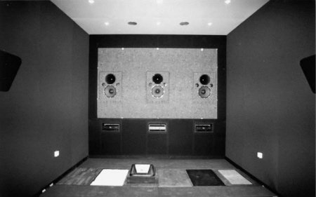
Figure 6.15 The Foley room at Cinemar, with the perforated screen dismounted and the different walking surfaces, for the recording of footsteps, clearly visible. This room, with a mixing console installed, can also be used for pre-mixing ‘stems’ of dialogue, music or effects, hence the surround loudspeakers which are visible at each side of the photograph. For this reason, the commonly used false doors and windows, for recording opening and closing sounds, are removable so as not to interfere with the room’s mixing capability
The construction of the room shown in the figure is generally similar to the principles shown in Figures 5.1, 5.3, 5.4 and 5.5. The front wall needs to be very rigid in order to provide an extended baffle for the loudspeakers, and so cannot be absorbent at lower frequencies. At higher frequencies, the perforated screen is also fairly reflective. However, in use, the actor will be facing the screen, and the microphone(s) will be pointing away from the reflective front surfaces of the room. As the rest of the room is highly absorbent, and the microphones which are used tend to be cardioid in their response pattern (in order to minimise the room sounds in general), the reflective front wall tends not to be a problem.
Figure 6.16 shows a different concept of Foley room design. In this case, the room is ‘constructed’ from 10cm of polyurethane, open-cell foam of 80 kg/m3 density, glued to the structural wall surfaces. Next, a 3.5 cm layer of panels of ‘Celenit’ was glued to the foam. In each case, the glue was a contact/impact adhesive. (This type of construction was described previously in Section 5.11.) On the right-hand wall of the room shown in the figure, a door and a window can be seen. These are for recording the sounds of doors and windows being opened and closed, and also the sounds of people knocking on them. They do not actually lead to anywhere, but are simply mounted on the surface of the wall.
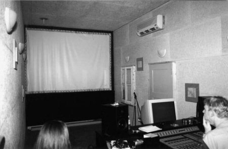
Figure 6.16 A Foley room in the Tobis complex in Lisbon, Portugal
The ceiling of the room is made from the same foam and Celenit, but glued to plasterboard fixed to wooden beams at 60cm centres. A 30cm cavity, lined with cotton-waste felt, gives rise to good low frequency absorption. The overall effect is a room with a very low decay time over a wide frequency range, enabling the recording of sound effects with a very low level of room colouration.
6.18 Summary
Strictly speaking, a live room is one where.
Some rooms with appropriate acoustics can be inspirational to the musicians. Idiosyncratic rooms tend to add variety to a studio’s facilities, but are much less flexible than more acoustically controlled rooms.
Non purpose-built recording rooms have often been found to be excellent for recording, partly due to the fact that they have not been built inside acoustic isolation shells. However, this can also limit their usability in some circumstances.
All materials of construction tend to impart some of their sonic characters to the rooms from which they are built.
Live rooms tend to come in two basic types: reverberant or reflective (bright). In live rooms, the directional characteristics of loudspeakers and microphones can greatly influence the recorded sound.
Live rooms feed energy back into acoustic instruments, producing a sound and a tactile feel that cannot be achieved by electronic post-processing. They can therefore affect a performance in their own, unique ways.
Spacially distributed instruments, such as a drum kit, drive the room differently according to the position of each part of the instrument.
Usually about 20% of the surface area of a room needs to be acoustically changed before it has a significant influence on the overall sonic characteristics of the room.
Adjusting the degree of irregularity on the surface of a stone wall can greatly affect the acoustics of a room. More relief leads to more diffusion. Greater depth of irregularity leads to diffusion down to lower frequencies.
The modally controlled range of a room is bounded by the large-room frequency and the pressure zone.
Much orchestral music has been composed with live performance as the principal objective. Modern studios do not always conform to the expectations of the composers. Much orchestral recording is therefore carried out outside of conventional studios.
Lateral reflexions can be important, both for the recordings and the musical performance.
The optimum RT60 for orchestral recording tends to be from 1.6 to 2.5 s at mid frequencies.
Many psychoacoustic factors need to be taken into account when designing spaces for orchestral recording.
Recording personnel should be attentive to the needs of musicians if the best overall results are to be achieved. Lack of thought can lead them to break up the acoustic character of a room solely from the point of view of the recording techniques, which can make the job of the musicians much more difficult.
Foley rooms, for the recording of incidental sound effects for cinema and video sound tracks, need to be acoustically dead so that the recordings can be artificially matched to the sound required by the picture.
References
1 Morfey, Christopher L., Dictionary of Acoustics, Academic Press, London and San Diego (2001)
2 Lubman, D. and Kiser, B. H., ‘This History of Western Civilization through the Acoustics of its Worship Spaces’, Proceedings of the Seventeenth International Congress on Acoustics, Rome (September 2000)
Bibliography
Barron, M., Auditorium Acoustics and Architecture, E & FN Spon, London, UK (1993)
Beranek, L., Music, Acoustics and Architecture, John Wiley & Sons, Chichester, UK (1979)
Kutruff, H., Room Acoustics, 4th Edn, E. & F. N. Spon, London, UK (2000)
Beranek, L., Concert Halls and Opera Houses, Springer-Verlag, New York, USA (2004)