
Flattening the Room Response
Subduing the room effects. Further discussion on electronic room equalisation. Standard listening rooms. The concept of a listening room. Close-field monitoring. The two near-fields.
From the discussion in Chapter 11, it can be seen that the influence of a room on the response of a loudspeaker is not trivial. In domestic circumstances, the degree of response variation is enormous, and ±10 or 12 dB is no exaggeration, even before the public get their hands on the ‘tone’ controls. Clearly, for critical listening, such response variability is absurd, so for professional recording studios an entirely different approach is needed if there is to be any hope of tonal consistency between recordings.
In the days of mono, it was usually not too difficult to find a combination of loudspeaker position and listening position which could avoid the worst modal disturbances in a room. The listening distance could also be adjusted to allow some control over the direct to reverberant sound balance. Indeed, when listening in mono, the ambience of the listening room is an important part of the experience, because the mono signals emanating from a point source in a relatively dead room can be rather uninspiring. Books on loudspeakers and hi-fi from the 1950s, such as those by Briggs,1,2 deal at great length with means of adding diffusion and ‘life’ to loudspeakers in order to help to spread the sound stage. Such ideas almost became taboo in the stereo era because the general tendency would be for the stereo definition to suffer if the sources were diffuse, although the advent of distributed mode loudspeakers (DMLs) is currently challenging that thinking to some degree.
The old mono sound control rooms in music recording studios were generally rather similar to the broadcast control rooms of the same era. Surfaces were usually parallel, and treated with whatever degree of acoustic treatment that was deemed necessary in order to achieve a decay time of half a second, or thereabouts. Many of these rooms were awful when stereo systems were installed in them. It was no longer so easy with stereo to make the positional changes that facilitated the ‘optimisation’ of mono rooms. A triangle had to be maintained between the two loudspeakers and the listener(s). Many options of placement were no longer workable, because when one of the loudspeakers was moved into a good position, the triangulation could force the other loudspeaker into a totally impractical place. Even by 1970, in a major recording centre such as London (UK), the number of stereo control rooms that a broad consensus of recording personnel considered excellent were pitifully few.
Many people in the industry knew a good deal about what the problems were, but a lack of knowledge about how to solve them, together with established practices such as the presence of tall metal racks and the use of rather ‘industrial’ furniture in general, delayed significant progress. What is more, domestic high fidelity systems were not in widespread use, so even many of the bad control rooms were still capable of quality-control monitoring way ahead of what could be heard in the vast majority of homes. The pressure to improve control-room acoustics was still largely driven by the people in the industry who knew that they could do better. What a recording sounded like on the average radio was already an important factor, at least for popular music recording, so the small loudspeakers provided on or in the mixing consoles were used to make a crude comparison. Nevertheless, the general trend in the industry was to try to advance, and to make better recordings.
12.1 Electronic Correction Concerns
By the mid 1970s, the majority of top studios around the world were using monitor equalisation to try to achieve a more standardised frequency response at the listening position. This was almost invariably done by means of putting pink noise into each loudspeaker system in turn, and adjusting graphic equalisers to give the desired response at the listening position (usually flat, with a slight top-end roll-off) on one of the newly available, third-octave, real-time analysers. The development of solid-state electronics had enabled the production of portable analysers, spanning 20 Hz to 20 kHz in third-octave bands, which displayed the output from a microphone or an electronic input in real-time (i.e. as it happened). Previous methods of room measurement had often involved the use of bulky equipment, which measured each band sequentially. The overall response usually had to be analysed some time after the event (hence not in real-time). In some ways though, the apparent simplicity of use of the portable equipment led to its use by many non-acousticians, who often grossly misused it in totally inappropriate circumstances.
By the late 1970s, the warning bells began to sound when it started to be realised on a widespread basis that rooms which were supposedly equalised to within very tight limits were often still sounding very different to each other. Over the next few years the whole concept of monitor equalisation came into serious question, but by that time, the idea that professional studios used room equalisation had become so deep in the folklore of audio that the misuse continues to this day. Although only a small proportion of top-line studios now use monitor equalisation for response corrections, lower down the scale of professionalism equalisers can still be found in many recording studios staffed by people of lesser experience. Somewhat perversely, the studios that do still use monitor equalisation are often the ones with the less acoustically controlled rooms, and it is in these rooms where the use of equalisers is least appropriate.
It was well understood that the critical bands of human hearing were in one-third octaves, and that the ear ‘sampled’ loudness in packets every 50 ms or so. It thus seemed to follow that if the one-third octave bands were adjusted by means of equalisers to provide more or less equal energy in each band (in response to a pink noise input, which contains equal energy in each one-third octave band), then a natural frequency balance would result. The poor waveform discrimination by the ear was thought to render inconsequential the phase anomalies brought about the application of the equalisation. Unfortunately, the reality was not so straightforward. Once again, results from hearing tests done on speech and noises had been taken as absolute, and applied incorrectly to musical perception.
The response plots shown in Figure 11.9 depict the pressure amplitude curves for one loudspeaker at two different places in a room. It ought to be intuitively obvious that if these plots represented the left and right loudspeakers of a stereo pair, then no simple application of such a crude device as a one-third octave equaliser could make the two responses identical. It would be like trying to repair a watch with a crowbar. Figure 12.1(a) shows an example of such a crude attempt at correction. The solid line shows a typical response dip caused by a floor reflexion, which is centred on the 160 Hz one-third octave band. The display on a one-third octave analyser would look something like the pattern shown in (b), which also clearly shows the dip at around 160 Hz.
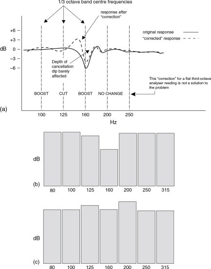
Figure 12.1 Attempted 1/3 octave correction of a floor dip. (a) In the above figure, the solid line represents the response of a loudspeaker in a room, affected by a floor reflexion. Below the curves are shown some typical boosts and cuts that could be applied by graphic equalisers to try to flatten the response. The result after equalisation may well read flat on a one-third octave spectrum analyser, but the true response would be more likely to be that shown by the dotted line, which subjectively may be no better than before the supposed ‘correction’ was applied. (b) The original response [the solid line in (a)] may well look like this on a one-third octave analyser, but attempts at correction would probably, by raising the 160 Hz band on a graphic equaliser, give rise to a response as shown in (c). (c) This response, resulting from a boosting of the 160 Hz band, could be further corrected to overall flatness by manipulating adjacent frequency bands, but any resultant overall flat reading would, in fact, still have a response like the dotted curve in (a)
The typical ‘fix’ by means of equalisation would be to raise the 160 Hz band until the analyser showed it to be up to the reference level, but this would also raise the adjacent bands, as shown in (c). Subsequent downward adjustment of the 125 and 200 Hz equaliser controls would tend to flatten the display, but the 100 and 250 Hz bands may then need raising a little. A process of reiteration could probably reach a situation whereby the one-third octave analyser showed a flat display, but only after the manipulation of controls up to one octave away from the narrow dip. When looked at in finer detail, it would be revealed that the true response after ‘correction’ would be that shown by the dotted line in Figure 12.1(a), which in fact looks no more correct that the response with the original dip, despite now having equal energy per one-third octave band.
So, what would have been achieved by all this equalisation? A dip at 160 Hz would still exist, but it would be flanked at either side by small peaks. This is not a correction, and neither is it necessarily an improvement. The direct signal, which was flat, would now be exhibiting a response similar to that delineated by the knobs on the equaliser – that familiar pattern of one band up, the next band down, the next up, the next down, and so on. This is only detrimental to the direct signal, and is in no way an improvement. The phase response, and hence the transient response of the direct signal would also have been altered, and this again could only be detrimental to the natural character of the sound. All in all, the damage done would have been much greater than any derived benefit, but such has been, and still is, the fate of thousands of studio monitoring systems in inexperienced hands.
An acoustic correction of the response dip could be achieved by putting mattresses on the floor between the loudspeakers and the listener. This is hardly a practical solution, but some recording studio designers have installed ‘pit traps’, or other in-floor absorption systems, to address this common problem. An electro-acoustic solution is shown in Figure 12.2, but this is more a function of a loudspeaker being designed to reduce floor dip effects rather than being a fix for a floor dip problem on an existing loudspeaker. The fact is that there is no effective electronic fix to the floor dip problem, because even digitally adaptive flattening can introduce unwanted artefacts. The saving grace is that such response dips are usually of quite narrow bandwidth, and that the ear’s sensitivity to them is low. In many ways, however, the ear’s sensitivity to the effects of attempts to correct the problem is such that many solutions are subjectively worse sounding than the problem itself.
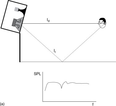
Figure 12.2 (a, b) Typical floor reflexion disturbance. (a) The superimposition of the reflected wave on the direct wave tends to produce a combined response similar to that shown above. The extra length of reflected pathway (lr) over the direct pathway (ld) causes summations and cancellations at different frequencies, and a deep cancellation around one frequency, where the distance lr − ld equals half a wavelength
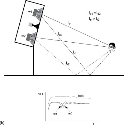
Figure 12.2 cont. (b) Non-minimum phase response-dip correction by the addition of a second
Another problem with electronic equalisation is that any boosts in level eat into the headroom of the monitor system. A 6 dB boost in one frequency band would require the amplifiers to supply four times the power at those frequencies. In cases where the sonic improvement due to the equalisation is marginal at best, the loss of headroom and possible resultant increase in distortion are further good reasons to avoid the use of monitor equalisation. In reality, there are three bona fide uses for monitor equalisers:
- To correct for minor discrepancies in the loudspeaker drive units when these are of a minimum phase nature.
- To compensate for any acoustic gain caused by the proximity of boundaries.
- To apply a desired curve the monitor response (such as the gentle high frequency roll-off which many studios employ, or cinema standard equalisation, or when high SPLs are normal).
All of the above are amplitude/frequency corrections. It is entirely appropriate to use amplitude/frequency corrections as long as the filters being used are of low frequency driver. By mounting a second low frequency driver vertically above the other one, the floor dips are displaced due to the different reflected path lengths. The total response, as shown above, shows an almost complete absence of response irregularity (after Kinoshita, Rey Audio, Japan) an appropriate quality and do not introduce any extra distortion or loss of response transparency. What cannot be treated by frequency domain corrections are time domain aberrations, such as those caused by room reflexions or resonances. Crossover filter induced dips are also not correctable by traditional equalisers, because of the delays inherent in the filter circuits. These are akin to the dips produced by electronic or tape-delay phasers, and almost anybody who has used studio equipment will be aware of the fact that although a phased sound sounds equalised, no equaliser in the effects rack can be used to de-phase the sound.
Clearly, therefore, from the evidence presented in this section, electronic correction was never going to be the answer to the standardisation or the sonic neutralisation of control rooms.
12.2 The Standard Room
In Section 5.3.2, reference was made to the preferred ratios of room dimensions for the achievement of the most even spread of modal density within a room.
The Bonello Criterion was also discussed. The preferred ratios led to the concept of the ‘standard listening room’. The primary use of such rooms was so that broadcasting companies and equipment manufacturers could assess their work in a set of reference conditions that were reasonably repeatable in other, not identical, but similar rooms in other places. The idea was that frequency balance, distortions, tonal colouration, stereo imaging and other aspects of sound could be reasonably assessed in meaningful ways. Accurate comparisons obviously could not be achieved in ad hoc conditions. For European homes, an International Electrotechnical Commission (IEC) standard3 for listening tests on loudspeakers recommended a reverberation time of 0.4 (±0.05) seconds between 250 Hz and 4 kHz, with a maximum of 0.8 seconds at low frequencies. A room volume of 80 m3 was also recommended, which could typically be a room of approximately 6.5 m × 4.5 m × 2.8 m.
The recommended specifications in these standards are intended to represent typical domestic listening conditions, and it would seem reasonably logical to record and mix music in conditions typical of those in which the results were intended to be heard. The problem with this concept is that what is statistically typical may not be representative of the majority of cases. The number 5.5 may be the statistical average of the integral numbers from 1 to 10, but although it may be reasonably representative of the numbers 4, 5, 6 and 7, it is not a reasonable representation of the majority of the numbers in the range, such a 1, 2, 3, 8, 9 and 10.
Another drawback to the use of such rooms for recording control rooms is that the colourations inherent in such designs are too great and too different from room to room for the critical assessment of the timbre of a recorded instrument. Furthermore, the reverberation time, in particular at low frequencies, is far too long for the recording and mixing of ‘dry’ sounds, such as produced by synthesisers. Much electronic music simply fuses into a blur in 0.8 s of low frequency reverberation, which the IEC specification allows. Whilst it is perhaps true to say that the colouration and room-to-room differences could be reduced by means of adequate diffusion, this was never a part of the specifications, which called for specific acoustic treatments such as those shown in Figure 12.3.
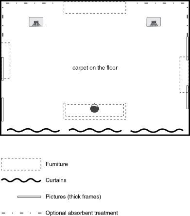
Figure 12.3 An IEC listening room. Recommended layout of a typical domestic listening room. By placing the loudspeaker systems along one of the longer walls they can be positioned away from the room corners at different distances from the nearest boundaries. The listener is then also able to sit near the boundary opposite the loudspeaker systems, away from the central part of the room where nodes occur at low frequencies
It should also be noted that the IEC rooms were based on a European standard, which is perhaps relevant for European broadcasting companies and national record companies. However, the music recording industry is very international, and as record buyers pay the same money for a recording, whether they live in an Indonesian wood hut or a Scottish castle, it would seem that they deserve equal consideration. Perhaps one of the things that most discredits the concept of the standard room is that there is no set position for the loudspeakers. All the rooms of different shape that lie within the IEC room specification will have different modal patterns. Whilst these modes are all intended to be evenly distributed, they will not all be driven. The loudspeakers will, due to their position, couple to some modes more strongly than to others. Therefore, with two different pairs of loudspeakers in two different IEC rooms, even with less than a one metre difference in any room dimension and with the loudspeakers placed more or less in corresponding positions, the response differences, and hence the perceived colouration, may be significant. All the modes could only be driven by the siting of the loudspeakers at the intersections of three room boundaries, such as in the corners of the floor or ceiling, but for many reasons this is a truly awful location for most loudspeakers.
Clearly, such ‘standard’ rooms, although intuitively appealing, are no answer to the problem of achieving the desired acoustics for control room monitoring. They tend to exist principally for loudspeaker manufacturers and broadcasters, for the verification of compliance with various other standards and specifications. In fact, the specification of international ‘standard’ rooms has often been done more to satisfy the most politically acceptable compromises, rather than the most psychoacoustically desirable compromises. This is not unreasonable, as the latter tend to be too subjective for worldwide agreement on standardisation. Overall, the use of IEC rooms has not been particularly widespread, and when conditions of super-critical listening are required, many professionals consider them unacceptable because of the degree of different colourations that they can produce. They still contain too many characteristics of idiosyncratic nature.
12.2.1 Beyond the Standard Room
In November 2006, Fazenda et al. published a paper on the subject of the use of modulation transfer functions (MTFs) (as introduced in sub-Section 11.5.5) to assess the difference in fidelity of reproduction as firstly the room sizes and secondly the dimension ratios were changed.6 The third change made to the rooms was the degree of modal damping, and it was shown that only this aspect of room control could significantly improve the accuracy of the perceived signal received by the ears from a loudspeaker across a listening room. A related paper by Harris et al. investigated the psychoacoustic link between the MTF and perceived quality of the low frequency reproduction.7 Walking around a listening room will take the listener through regions of different modal effects, and will give rise to a perception of a changing frequency response, but in general there will not be a noticeable change in the quality of the music. However, fine detail may be lost as the listener goes further away from the loudspeakers in a relatively lively room, or listens on the anti-node of a strongly excited mode.
The above effect was shown in terms of MTF in Figure 11.31, and Fazenda has shown that the only viable way to reduce this effect of distance is by restricting the modal Q by damping the room.6, 8 In terms of the use of standardised room ratios, and with implications of 0.4 second mid-band decay time being suitable for high definition listening, the case has now been effectively closed. Such rooms do not meet the requirements for detailed quality control listening.
Frustrated by years of attempting to use their ‘reference’ rooms to assess all aspects of loudspeaker responses, the KEF loudspeaker company approached the author in 2006 about the design of three listening rooms to be constructed in their new factory in southern England. One of these rooms was to be a quality control room, for listening to the responses of the loudspeakers themselves. The second room was to be constructed in the manner of a typical British domestic lounge, and the third room was to be constructed in the typical manner of a Californian domestic lounge. The reason behind this decision was that after forty years of trying to use single rooms for multiple purposes it finally became apparent that no single room could be used to extrapolate the complex performance of other rooms of significantly different construction. However, in this case, KEF were very concerned about the British and American markets, and how loudspeakers aligned for typical British homes could sound bass light in many larger, wood-framed American homes; and vice versa. Listening rooms for the precise assessment of specific characteristics therefore tend to need to be built with those characteristics. Extrapolation from ‘standard’ conditions can be rather imprecise.
Nevertheless, work carried out by Genelec and JBL on a very wide range of listening conditions, from hotel alarm-clock radios to ghetto-blasters, from motor vehicles to discothèques, from Scottish castles to tropical wooden huts, from home theatre systems to headphones; the average of all the responses was FLAT! This, perhaps surprising result, suggests that control rooms in studios which are recording music for all reproduction circumstances should have flat responses if they are to be fair to all reproduction conditions. In practice, listeners then receive the responses according to the circumstances under which they are listening, and not a response which has been biased towards any specific listening conditions which may prejudice the enjoyment of music under different circumstances. A flat response is the fairest and the most representative response for a control room to exhibit.
Therefore, the work by Fazenda et al. is trying to arrive at a threshold of specification for a room decay which would allow flat mixing conditions and neutral timbral responses. It is expected that these listening conditions would, even at low frequencies, not be far different from what would be perceived when listening to the same loudspeakers in an anechoic chamber, but without the sensation of a dead environment. Some of the control room concepts described in later chapters also seek to achieve a similar goal, but control rooms are highly specialised rooms, often with flush-mounted monitor systems; they are not typical domestic rooms.
The aim of the new type of listening room is to be more tolerant of loudspeaker placement and listening position, yet to have acoustic characteristics with absolute minimal colouration of the sounds reproduced within them. Fazenda is therefore working towards a room, not with the most even modal distribution, but with all modes damped to a point where they are not subjectively considered to give rise to misleading colouration.
It could, of course, also be argued that such listening rooms as this would also not be typically domestic, but nevertheless they would allow quality control listening in rooms which were not acoustically bi-directional. The majority of top class stereo control rooms are acoustically bi-directional, so reversing the direction of the loudspeakers and listening position could be subjectively disastrous. Obviously, in these typical control rooms, arbitrary loudspeaker placement is not an option.
12.3 The Anechoic Chamber
Figure 4.2 shows an anechoic chamber used for acoustic measurement at Southampton University in the UK. The chamber has also been used for subjective/objective comparisons on loudspeakers. There is absolutely no doubt that anechoic chambers provide the optimum conditions for achieving the flattest transfer from the loudspeakers to the ears, but the problems with their use as control rooms are two-fold. Firstly, many people are nervous when entering such rooms because they are deprived of the aural sensation from the surroundings to which they are accustomed, and which they need psychologically for their sense of normality. One can become accustomed to working in such circumstances, but during listening tests involving many inexperienced people it has been usual for some of them to be on the verge of a state of panic. The second reason why anechoic chambers are not suitable for control room monitoring is that at least some lateral reflexions are needed in order to develop a sense of spaciousness. If these are missing, the sound field collapses totally into the plane between the loudspeakers. This is highly untypical of the listening conditions in which the end-result is likely to be heard. Anechoic listening is too far away from normality.
There are also two further reasons why anechoic conditions are not the answer to the control room problem. A large increase in loudspeaker power would be needed due to so much energy being absorbed by the boundaries, with the room giving no help whatsoever to the sound level. What is more, most loudspeakers are not designed for truly free-field operation, so it would be unlikely that very many commercially available loudspeakers would deliver their intended tonal balance in an anechoic chamber. Although the last two points are technically solvable, the first two are not, and so they are the prime reasons for the rejection of anechoic chambers as ideal control rooms. The cost of suitable wedges, at around €1,000 per square metre, is also a consideration. Finally of course, in order to be effective down to low frequencies, the rooms also have to be huge.
12.4 The Hybrid Room
In a paper presented to the 1982 Audio Engineering Society convention in Anaheim, USA,4 a proposal was put forward for a room such as is shown in Figure 12.4 as a solution to the neutral listening-room dilemma. The equation that they proposed was:
Anechoic chamber + Reverberation chamber = New standard room
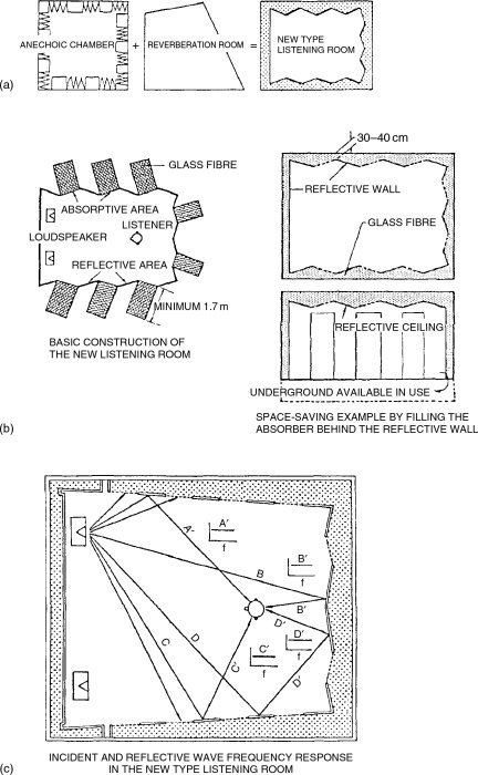
Figure 12.4 The Ishii and Mizutoni proposal
Their idea was to use large areas of full-frequency-band absorption, alongside large areas of full-frequency-band reflexion. This was achieved by the use of recesses almost two metres deep, filled with glass fibre wool, adjacent to slabs of heavy reflective materials. The juxtaposition would also lead to considerable diffusion. The system maintained a reverberation time of about 0.4 s with no more than 0.1s total deviation between 20 Hz and 20 kHz. The rigid walls were non-parallel in order to prevent slap echoes (flutter echoes), and were massive so as not to vibrate and produce any resonant colouration.
The idea was well conceived. Wide-band absorption and wide-band reflexion, spacially well distributed and automatically providing good diffusion and some specular reflexions without flutter or resonance. The drawbacks, however, are numerous. The loss of two metres depth on each of three wall surfaces, plus the need for sufficient distance from the reflective surfaces to avoid the reflexion returning to the listening position too early, means that all such rooms would necessarily be large; too large, in fact, for the spaces available for control rooms in most studios. As discussed in Section 7.2, such control measures are all time and wavelength related, and so to scale them down in a smaller room is not possible. Despite the paper referring to its use in studios, this room concept (and the T60 of 0.4 s) still seemed to relate more to listening room standards rather than the somewhat more critical conditions necessary for control room monitoring.
Nevertheless, the Ishii-Mizutoni paper proposed a room that would exhibit generally acoustically neutral listening conditions, where the direct to reverberant sound fields could be balanced by adjustment of the distance between the loudspeakers and the listeners. Interestingly, though, in their AES paper, they stated ‘The back of the front stage should be made of all rigid wall construction, because as a listening room, the difference in position of the test loudspeaker should be minimised’. This is interesting inasmuch as it recognises the need for a relatively fixed loudspeaker position for repeatable critical assessment, in this case very close to a massive, rigid wall.
Large broadcasting organisations such as the British Broadcasting Corporation (BBC) may need to transfer programme material between many studios in many different locations. Staff may also frequently move between studios, and to work efficiently they need to be able to settle quickly into an unfamiliar room with a minimum of time for acclimatisation. They need to work rapidly and reliably, and to feel confident that the ensuing broadcasts are well balanced in people’s homes. There is also a tendency for the broadcast industry to rely on free-standing loudspeakers, with all the attendant problems of edge diffractions, the confusion caused by rear radiation, and the response variability with respect to position.
Broadcasting staff often have their own ways of working, which necessarily differ from the music recording industry, and any new rooms that are introduced into a studio complex usually need to be closely compatible with existing rooms. The deader acoustics of many music industry control rooms are generally not well liked in the broadcast world. The tendency is still to favour rooms with characteristics not unlike the IEC rooms, but this type of construction is not always appropriate because of limitations on size.
In 1994, Bob Walker presented a paper5 on a newly developed type of room for the BBC, which was to exhibit a relatively uniform decay time with frequency. It had the added specification that no reflexions should arrive at the ear within 15ms of the direct signal, and that no reflexions arriving after that time should be more than −15 dB relative to the direct signal. The concept is shown in Figure 12.5. The ceiling, as can be seen, is of generally similar shape to the walls, which seems logical considering the three-dimensional expansion of the sound waves. The floor dip problem, discussed in Chapter 11, is partially blocked by the siting of a mixing console between the loudspeakers and the listener.
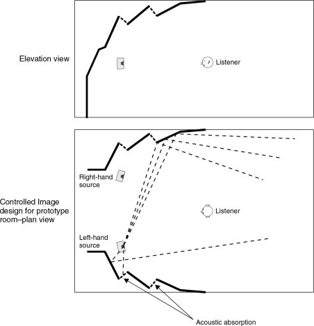
Figure 12.5 Controlled reflexion room, in the style of Bob Walker, for free-standing loudspeakers
The design concept relies on the positioning of reflective surfaces in such locations that they will not reflect energy from the loudspeakers directly towards the listener, which is not as easy as it may seem. In reality, unlike the images shown on computer ray-tracing programs, the sound waves do not travel in straight lines according to Euclidian geometry. They travel as expanding waves that are greatly influenced by diffraction effects at most audio frequencies. The diffraction ensures that non-specular (i.e. unlike light) reflexions will travel in unpredicted directions, only to be re-diffracted from other boundary discontinuities. The design of such rooms is therefore not a simple matter. Nevertheless, the above concept has much to offer in some difficult circumstances, and its concepts are valuable when free-standing loudspeakers must be used.
12.6 On Listening Rooms in General
When rooms are to be used for listening to music for serious enjoyment, almost all of the concepts discussed so far in this chapter must be taken into account. Simply placing loudspeakers in any convenient location will not suffice. It must be understood that in a highly reverberant room, with little furniture and plastered walls and ceiling, it is unlikely that pleasant listening conditions could be achieved no matter what type of loudspeakers were used, nor however carefully they were positioned. What is needed, when listening to music for pleasure, is a relatively flat amplitude response from the room/loudspeaker combination, and a quantity of reverberation that is appropriate for the music.
Except for the purposes of the quality control of recordings, it is probably true to say that all recorded music benefits from a little reverberation in the listening environment. Surround sound systems, which can provide different ambiences for different types of recording, probably benefit from being reproduced in rooms with reverberation times slightly lower than the shortest reverberation time in any recordings to be auditioned in them. However, for stereo reproduction in relatively small rooms, reverberation times (or more correctly in these cases, decay times) should be between about 0.3 and 0.5 s from 100 Hz to 1 kHz, with allowable increases below 100 Hz and reductions above 1 kHz. In general, rock music and electronic music with high transient contents tend to favour the shorter decay times, whilst much acoustic music tends to favour the upper limits.
Control of the decay time can be accomplished by furnishings or by specific acoustic treatments, but the situation is greatly affected by the structure of the room. Diaphragmatic walls and ceilings, such as those made from timber and plasterboard (variously known as sheetrock or Pladur) tend to produce better listening rooms than those made from granite blocks, in which large low frequency build-ups are commonly encountered. This is the reason why some loudspeaker manufacturers, with their principal markets being in known countries, specifically tailor the low frequency responses of their products to take into account the absorption characteristics of the typical structures and furnishings of the most common homes in which their products will be used. Flat anechoic chamber responses are most definitely not the objective in such cases. A flat response in the end-use environment is what is being sought.
One of the main requirements of any length of reverberation time is that it should not vary significantly between adjacent third-octave bands, and that it should show a slight monotonic roll-off above about 100 Hz. In smaller rooms, the decay time below 100 Hz will usually fall, but in larger rooms it can be allowed to rise, though the 50 Hz reverberation time should not exceed twice that at 1 kHz. If the reverberation/decay time is not smooth, it will colour the reproduced sound, because certain bands of frequencies hang on when the rest of the music has decayed. When such cases exist, they are usually the result of the existence of poorly damped resonant modes.
In purpose designed listening rooms, internal room structures can be built if the main structure is unsuitable. Figure 12.6 shows a typical wall structure that could be used in a serious listening room. This is a useful means of damping the room modes and reducing the reflected low frequency energy. Bookcases on rear walls (i.e. facing the loudspeakers) can produce excellent diffusion, and heavy upholstery and deeply folded curtains are effective wide-band absorbers. Wooden floors tend to absorb much more bass than do concrete or stone floors. The absorption of deeply folded curtains, however, is affected by their distance from the walls. As with the partition wall shown in Figure 12.6, the greater the space between the absorber and the structural wall, the greater will be the very low frequency absorption.
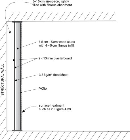
Figure 12.6 Composite acoustic control wall. The wall shown in this figure is a combination of membrane absorber, panel absorber and amplitude reflexion grating. By such means, a room can be well-controlled down to very low frequencies, and the internal ‘life’ in the room acoustic can be adjusted by varying the ratio of hard to soft surfaces on the surface, either strip-by-strip or section-by-section
12.7 Close-Field Monitoring
From the concepts discussed in this chapter, it can be seen that many apparently obvious (and other less obvious) solutions are not necessarily solutions at all to the problem of creating ideal critical listening conditions for music in stereo. It is true that chaos effectively rules in the domestic listening world, because the range of domestic listening conditions must include loudspeakers of all qualities, response variations of at least ±10dB, and decay times of between (usually) 0.3 and 1.2s; so what is the reference point? How do we find a set of monitoring conditions which will allow recordings to be produced in the studios which will ‘travel’ to the wide range of domestic listening conditions? An answer is needed so that the people making the recordings can be reasonably sure of the balance of instruments that will be heard in the diverse range of home situations.
In the early 1970s, with no apparent answer to the above problem, a fashion swept through the western recording world. It was the use of the Auratone 5C Sound Cubes. These consisted of boxes about sixteen centimeters cubed usually placed on top of the mixing consoles, which were used to check mixes for compatibility in domestic circumstances (note to non-native English speakers – sixteen centimetres cubed –16cm ×16cm×16cm – 4096cm3). The Auratones consisted of a 4.5-inch loudspeaker (110 mm) in a sealed box which, for their time, had an unexpectedly good low frequency response. They led the way to what became known as ‘near-field’ or, more correctly, ‘close-field’ monitoring. These small loudspeakers, in stereo pairs at close range, gave surprisingly reliable reproduction. In most circumstances, the listening distance of around one metre ensured that monitoring was carried out within the critical distance, except at the lowest frequencies (of which there was very little, anyway). This helped to introduce a form of standardised monitoring conditions – listening within the close field of Auratones on top of a mixing console. Of course, the limitation was that the loudspeakers could not be considered full range, so what was going on at the lowest and the very highest frequencies could not be heard. Nevertheless, in conjunction with larger monitors, recording personnel began to learn how to use the technique, and often found that the more direct sound which the close field provided allowed them to work more rapidly and with better compatibility with the bulk of domestic listening circumstances. This subject will be raised numerous times in later chapters, and will be discussed at length in Chapter 19.
By the early 1980s a new contender arrived for the role of standard reference; the Yamaha NS10M. This was originally conceived as a domestic hi-fi loudspeaker, but it was a commercial failure as such. However, it found rapid international acceptance as the new close field monitor. Louder and deeper than the Auratone, this two-way system, shown in Figure 12.7, provided something on which the heavily synthesiser orientated music of the day could be heard more realistically. The high driver failure rate of the original NS10s led Yamaha to create the ‘NS10M Studio’, specifically designed for studio use with greater power handling and similar sensitivity. Although there were some early complaints that it did not sound quite the same as the original, to which so many people had become accustomed, the studio version nevertheless soon became a de facto reference for the next 15 years or more.
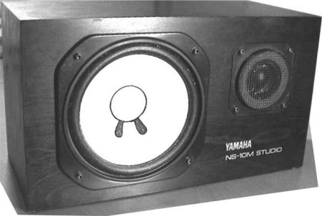
Figure 12.7 The Yamaha ‘NS10M Studio’. Shown, incidentally, as it should not be used, see Figure 18.5
Clearly, the use of the newly available, relatively wide response, compact loudspeakers, which had enough SPL and sufficient damage tolerance for adequate monitoring, opened up new possibilities for close field monitoring. The need for this, and the various ways in which it was taken up, was a clear statement by the recording industry that control rooms and their monitor systems were, in general, not performing as well as they should. In many ways, it was a sad reflection on the state of control room design. It seemed like almost a whole industry had abandoned the control rooms and withdrawn into the close field.
Incidentally, the term ‘close field’ is preferred because ‘near field’ already has two, well established and clearly defined acoustical senses, neither of which relate to the way that small monitors are used in studios. The geometric and hydrodynamic near fields are described in the glossary. Briefly, however, the geometric near field exists where the distance from a measuring point to all parts of the radiating surface cannot be considered to be equal. This depends on wavelength, so the extent of the near field is frequency and sourcesize dependent. This is why, when calculating sound pressure levels by counting back to the source, and increasing the value by 6 dB for each halving of distance, one does not get infinite power at the source. For example, in a free field, 100 dB at 1 m would suggest 106 dB at 50 cm; 112 dB at 25 cm; 118 dB at 12.5 cm; and 124 dB at 6.25 cm; until infinite pressure at the diaphragm. In reality, at some distance, the SPL will reach a level which will be the limit at any given frequency. Going closer to the source diaphragm would not produce any higher SPLs because one would be entering the geometric near field.
Another type of pseudo near field exists with multi-way loudspeakers, when the listening distances are so short that, in effect, the highs can be heard coming from the tweeters and the lows from the woofers; in other words, where the multiple drive elements fail to blend into one common, apparent source. In this region, small movements of the head can lead to large changes in the sound character, and in such conditions of inconsistency, monitoring would be unwise, if not ridiculous. The frequency balance would not be consistent within this near field, so it is wiser to listen in the close field.
In general, the popularity of close field monitoring suggests that listening within the critical distance is desirable not only for the perception of detail, but also because the frequency response (pressure amplitude response) of the loudspeakers are more consistent, and less variability thus exists between what is heard in different rooms. There is no reason why this cannot also be achieved using large monitors in well controlled rooms, but the main obstacle in the development of such control rooms was a very deeply entrenched reluctance to accept that what was required of the IEC listening rooms, in terms of modal help, decay time and reflexions, could be dispensed with. Somewhat ironically, many of the people demanding loyalty to the old ideas were themselves totally rejecting them by their reliance on close field working.
When people are listening at normal distances from loudspeakers, they are usually listening at or beyond the critical distance, as explained in Chapter 11. They are therefore listening to the room sound at a level that is equal to or exceeds the direct sound. If the music is cut, the natural decay down to 60 dB below the previous level would be what is perceived from the room. However, when listening in the close field, the direct sound may be up to 10 dB higher than the room ambience. In such cases, when the music is cut, the sound level immediately drops by the difference. Figure 12.8 shows the two cases. In the latter, it is when the room sound has decayed only by 50dB that it will be perceived to be at the − 60dB level relative to the music. Therefore, when wishing to work in the close field, a person is effectively requesting to work in a room with a decay time that is shorter than the nominal decay time in the room in which they are working. The practice of requesting a given room decay time (RT60, T60), rejecting the main monitors as being too affected by the room, and then electing to work in the close field, is a triumph of ignorance over acoustics. The answer could seem to lie in reducing the room decay time for the large monitoring systems; then, if the room were deemed oppressive, increasing the reflected energy from the speech and actions of the people working within the room by means of surfaces out of the line of sight of the loudspeakers. Now we are finally beginning to touch upon the subject of control room design.
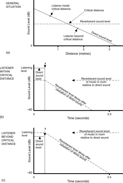
Figure 12.8 Perception from within and beyond the critical distance. (a) General situation. (b) When the signal is cut at time x, a sudden drop in level is perceived, then the reverberation is heard to decay in accordance with the nature of the room. (c) If the listener is already in the reverberant field, no sudden drop in level is noticed when the signal is cut at time x, only the steady decay of the reverberant field is perceived
12.8 Summary
The control of a room, to flatten the transfer function from loudspeaker to ear, is best achieved acoustically.
In the case of mono, the loudspeaker and listening positions can be adjusted to find a best compromise response, but this is more difficult in stereo, where a triangular geometry between two loudspeakers and the listener must be maintained.
Monitor equalisation is not an answer, but perversely it is usually the studios with the least acoustic treatment – the ones least able to be corrected by equalisation – that are the ones where it is currently most likely to be found in use. The tendency is for monitor equalisers to shift problems around rather than to cure them. Equalisers can only legitimately be used for the correction of amplitude/frequency problems that are not caused by time domain effects.
IEC standard listening rooms are generally too coloured for critical listening purposes.
Anechoic chambers are too far removed from real listening conditions to be used for music mixing.
The Ishii-Mizutoni concept is too bulky, and will not scale because of wavelength dependency.
The Walker/BBC rooms are a reasonable solution when free-standing loudspeakers must be used.
The rooms used for serious listening for musical enjoyment are not necessarily the ones best suited for critical quality control listening.
Heavily damped rooms, with low modal Qs, offer better room-to-room compatibility.
The concept of close field monitoring has, in effect, been a request for working inside, or quite close to, the critical distance. This can be reinterpreted as being a request for control rooms with a shorter decay time.
References
1 Briggs, G. A., Loudspeakers, 5th Edn, Wharfedale Wireless Works, Bradford UK (1958). [Later re-prints published by Rank Wharfedale Limited, into the 1970s.]
2 Briggs, G. A., Sound Reproduction, 3rd Edn, Wharfedale Wireless Works, Bradford, UK (1953)
3 IEC, Sound System Equipment, Part 13: Listening Tests on Loudspeakers, IEC Publications 268–13 (1983)
4 Ishii, S., Mizutoni, T., ‘A New Type of Listening Room and its Characteristics – A Proposal for a Standard Listening Room.’ Presented at the 72nd AES Convention, Anaheim, USA, Preprint No. 1887 (1982)
5 Walker, R., ‘The Control of Early Reflections in Studio Control Rooms’, Proceedings of the Institute of Acoustics, Vol. 16, Part 4, pp. 299–311 (1994)
6 Fazenda, B. M., Holland, K. R., Newell, P. R., Castro, S. V., ‘Modulation Transfer Function as a Measure of Room Low Frequency Performance’, Proceedings of the Institute of Acoustics, Vol. 28, Part 8, pp. 187–194, Reproduced Sound 22 conference, Oxford, UK (2006)
7 Harris, L. E., Holland, K. R., Newell, P. R., ‘Subjective Assessment of the Modulation Transfer Function as a Means for Quantifying Low-Frequency Sound Quality’, Proceedings of the Institute of Acoustics, Vol. 28, Part 8, pp. 195–203, Reproduced Sound 22 conference, Oxford, UK (2006)
8 Fazenda, B. M., Avis, M. R., ‘Perception of Low Frequencies in Small Rooms’, Proceedings of the European Acoustics Symposeum (Acústica 2004), Guimarães, Portugal (2004)