
Designing Neutral Rooms
The need for neutral rooms. What constitutes ‘neutral’. The concept and construction of large neutral rooms. The effect of shape on modal patterns. The effect of a room on a musical performance. Acoustic parallelism. Achieving neutrality in small rooms. Practical construction of a small neutral/dead room. Sound paths within a complex acoustic control structure. The pressure zone. Transfer of sound between high and low density media. Remnant micro-resonances. Dialogue recording rooms.
In the chapters so far we have looked at what a studio needs to be able to achieve; some of the properties of sound and hearing; the means of providing isolation; the internal acoustic behaviour of an isolation shell; and the means at our disposal to attempt to control the internal acoustics. What we can now do, therefore, in this chapter, is to apply the foregoing information to try to create a neutral, unobtrusive yet musically pleasing room. Of course, neutral rooms are not necessarily the most inspiring rooms to design, but here they make a good starting point, because the ensuing discussion will take us through a whole range of acoustic control principles. These can then be refined in later chapters when we begin to look at rooms with much more specific acoustics for their own specialised purposes.
5.1 Background
Historically, recording studios (the word ‘studios’ here meaning the recording spaces, as opposed to the control rooms), have been relatively neutral environments. This has been partly due to past recording studios having to cater for a wide range of recordings. Too much bias towards the needs of one specific type of music could lead to a restriction in the amount of work available for a studio. Furthermore, it was formerly often considered that the responsibility for the production of the sound to be recorded was in the domain of the musicians. The function of the recording studio was seen as being to record the sounds which the musicians produced, as faithfully as possible. The days of a somewhat more creative side to the recording process had still not arrived.
Contrary to what may often be expected, the ‘true’ sound of a musical instrument is not simply that which it would make in an anechoic chamber. This is because instruments were developed in the circumstances of more reflective or reverberant surroundings, and it is frequently the combined direct and reflected sounds which constitute the ‘true’ sound of an instrument – the sound as it is intended to be heard. Concert halls have long been rated by musicians according to how well they can perform in those halls. Players of acoustic instruments need a feedback from the performing space, as frequently the sound emission from the instruments are inadequate to give directly to the musicians the sensations required for optimum performance. String sections need to hear string sections, not a group of individual instruments. When they hear a section, they play as a section; but when they hear separate instruments their playing also often fails to gel into a single, homogeneous performance. Flautists seem almost always to need some reverberant help for their playing, be it natural, or fed electronically into their foldback. Woodwind players also seem to dislike too dry an ambience in their performing space. In fact, an anechoic chamber is a truly awful environment in which to play any instrument, and such an environment is not going to inspire any musician to the heights of creativity. Creativity is supremely important, as it would appear to be self-evident that an uninspired performance is hardly worth recording.
So, if we are not meaning a clinically accurate recording space when we speak of ‘neutral’ spaces, then what are we talking about? Essentially, a neutral environment is one which provides sufficient life to allow enough of the character of an instrument to be apparent, but which does not overpower the instrument with the character of the room itself. This means a smoothly sloping reverberation time (or rather, decay time) together with discrete reflexions which add life but do not dominate the natural sound of the instrument. Normally, such rooms will have decay times which rise as the frequency lowers. This is a function of most enclosed spaces other than very small ones, and when one considers the fact that most instruments have been developed for performance in such spaces, a recording area with similar characteristics would not be deemed unnatural. Rooms of different sizes, shapes and structures will have their own characteristic acoustics, but as long as those characteristics do not add any significant timbral change to the instrument they can be considered to be neutral.
In general, it is easier to make large neutral rooms than small ones. This is because of two main reasons. First, in large spaces, the resonant modes tend to be more evenly spaced across the frequency spectrum, whereas in small rooms, especially at lower frequencies, they tend to separate, as shown in Figure 4.14. Particularly in the upper bass region, unevenly spaced modes can become strongly audible due to the concentrations of energy beginning to add a strong character to the sound of the instruments in the room. Second, in larger rooms there is a greater period of time between the emission of sound from the instruments and the arrival of the reflexions. Floor reflexions are, of course, returned at similar time intervals in all sizes of rooms, but these are usually relatively innocuous, single reflexions, free of resonant characteristics. The more noticeable resonant modal energy must exist between at least two surfaces, and therefore, to reduce undue colouration of the sound, hard, parallel floor/ceiling combinations are usually avoided in studios. In large rooms the greater period of time before the first reflected energy returns to the instrument allows more time for the direct sound of the instrument to stand alone, and thus establish itself clearly in the perception of the listeners.
A further two reasons also lead to the later reflexions having less colouring effect. Reflexions from greater distances have further to travel, so when they do return, they will do so with generally less intensity than those travelling back from shorter distances (given the same surfaces from which to reflect). What is more, when reflexions arrive much more than 30 ms after the initial sound they tend to be perceived by the brain as reflexions, whereas those arriving before 30 ms have elapsed will almost certainly be heard as a timbral colouration of the instrument, and will not be perceived as discrete reflexions. This is, of course, the Haas effect (see Glossary). In a large room, therefore, the resonant modes and reflexions are usually heard as separate entities to the direct sound of the instruments. Unless the direct sound of an instrument is swamped by room sounds which are unduly long in time or high in level, its natural characteristic timbre will be clearly heard.
Generally, a recording room can be considered to be in the acoustically small category if it is impossible to be less than four or five metres from the nearest wall surface. Judicious angling of the ceiling, together with careful use of absorption and diffusion, can permit the use of ceilings of 4m or less with relative freedom from colouration, so an acoustically small room for recording purposes would tend to be less than about 10 m × 10 m × 4 m.
5.2 Large Neutral Rooms
To build an acoustically large neutral room is not a particularly difficult exercise as long as a few basic rules are followed. Parallel hard surfaced walls should be avoided, as these can support the strong axial modes which develop, reflecting backwards and forwards between the parallel surfaces. The effects of such reflexions on transient signals are those of ‘slap-back’ echoes, or series of repeats, usually with pronounced tonal contents which are often quite un-musical and unpleasant in nature. The parallel surface avoidance rule also relates to floors and ceilings. However, we should make a distinction here between what is actually heard in the room and what is heard via the microphones. Although the ear is often not unduly troubled by vertical reflexions, because it is much less sensitive in the vertical plane than in the horizontal plane, most microphones tend to be totally ignorant of concepts of horizontal or vertical. Therefore, a floor/ceiling problem or a similar wall/wall problem will be detected by most microphones in exactly the same way. Even though the ear may hear them very differently when listening directly, the perception when listening to a recording will be the effect as detected by the microphones. Consequently, when considering the subjective neutrality of a room, we must consider it from both points of reference: listening directly via human ears, and listening via microphones.
Unless two rooms are absolutely identical, not only in shape, size and surface treatments, but also in the structure of their outer shells, they will not sound identical. In reality, there are thousands of ‘neutral’ recording spaces in the world, but it is unlikely that any two will sound identical to each other. The achievement of acoustic neutrality is all a question of balances and compromises, but unlike the neutrality needed in control rooms, where repeatable and ‘standard’ reference conditions are needed, such uniformity of neutrality is not required in the studios. The concept of neutrality in a recording room therefore occupies a region within an upper and lower limit of what a room may add. All that is required is that the room sound is evenly distributed in frequency and is subservient to the sound of the instrument(s).
A parallel exists in the realm of amplifiers. Guitar amplifiers and hi-fi amplifiers are quite distinct devices, and normally cannot be interchanged. Guitar amplifiers have relatively high levels of distortions, but those distortions are chosen to be constructive and enhancing in terms of the sound of electric guitars. However, recorded music played through a guitar amplifier and loudspeaker will sound coloured, and will suffer from a lack of definition. The result will certainly not be hi-fi. Conversely, a guitar played through a hi-fi amplifier and loudspeaker (the neutrality of which are more akin to control room neutrality) will be unlikely to sound full-bodied or powerful. In a similar way it is thus entirely justifiable for a neutral recording room to add to the character of an instrument played within that room, as long as that character enhances and supports the instrument and does not in any way become predominant itself. Therefore, anything in the sound production side of the record/reproduce chain can be considered to be an extension of the instrument, and hence subjective enhancement is usually desirable. Conversely, things in the reproduction or the quality control sides of the chain must be transparently neutral, in order to allow the production to be heard as it is on the recording medium.
5.3 Practical Realisation of a Neutral Room
Neutral rooms are desirable for many types of acoustic recordings, but modern thinking places much more emphasis on the comfort of the musicians than was encountered in a great majority of the coldly neutral rooms which were prevalent in previous years. At each stage of our design we therefore need, to consider its effect on the musicians as well as on the purely acoustical requirements. Anyhow, it seems to be very widely accepted that floor reflexions are in almost all cases desirable, and indeed most live performance spaces have hard floors, so let us begin the design of our large neutral room with the installation of a hard floor.
5.3.1 Floors
Hard floors can be made from many materials, but they generally subdivide into vegetable or mineral origins. On the vegetable side we have a great variety of wood-based choices. There are hardwoods, softwoods, wood composites such as plywood, veneered MDF (medium density fibreboard), cork tiles, parquet, and reconstituted boards, to name a few of the most common types. In the mineral domain we have stone in its various forms, ceramic tiles, and concrete with resinous overlay, which is often used in television studios where cameras must roll over an extremely smooth, unjointed surface. Usually, in large rooms, wood prevails. It is aesthetically warmer, thermally warmer, less prone to slippage (both by people and instruments), and it is generally richer acoustically. Instruments such as cellos and contrabasses rely on the floor contact to give them a greater area of soundboard as their vibrations travel through the wooden surface. Mineral based floors do not ‘speak’ in the same way. Wood also represents more closely the flooring which musicians are most likely to encounter during their live performances, and, where possible, studios should seek to make the musicians feel at home. The necessity for this cannot be over-emphasised. The exact nature of the floor structure will usually depend on a multitude of factors concerning the structure and location of the building, but these things will be dealt with in later chapters.
It is very important that floors should not creak or make other noises when people are walking on them, nor should they rattle under the influence of vibrations from instruments or their associated amplifiers. For this reason the floors should be well damped, which means that the upper surface should be securely fixed to the mass layers below, such as shown in Figures 1.1 and 3.4. Domestic type floated floor systems, laid loosely on a layer of thin polyethylene foam, should not be used unless the foam is omitted and the boards are glued and pinned to the surface below them. They have a tendency to flap about under the influence of high levels of low frequencies if not well fixed down. The reason for not fixing them down in domestic use is that floating them on foam provides more isolation from impact noise, and the non-rigid fixing also allows them to expand and contract at different rates to the floors on which they lay. However, in the (hopefully) well-controlled temperatures and humidity of a professional studio, the expansion problems should not exist. Nevertheless it is just as well to match the base material of the flooring (on which the veneered surface is fixed) to the upper surface of the underlying floor. From this point of view the floor systems (such as Kahrs, Junckers, etc.) which use plywood or solid wood bases tend to be preferable to the ones with synthetic, resin-based under surfaces.
5.3.2 Shapes, Sizes and Modes
So, we now have a floor, but for the reasons already cited it is of necessity highly reflective, and it has done nothing to neutralise our reverberant isolation shell. We must therefore continue with the rest of the room to find some means of control. Our worst case starting point would be to have a cubic room, with all dimensions (length, breadth and height) equal. In the case of a cubic room, where all the pairs of parallel surfaces are equally spaced apart, the axial modes will all be similar in path length, and hence will all have similar resonant frequencies. This will lead to a strong resonant build-up at the frequencies associated with those modes. Furthermore, the axial modes are the ones which are considered to contain the most energy, and so those frequencies whose wavelengths correspond with the dimensions of the room will predominate, giving the room a highly tuned, strongly resonant character. Such a room would be a ‘one note’ room, with overpowering resonance destroying the musicality of almost any instrument played in it. At the other extreme, a room of rectangular plan with dimensions of height, breadth and length in the approximate proportions, 1:1.6:2.33 (see following paragraph) would give rise to a highly varied assortment of modal frequencies, and hence would exhibit the overall least coloured sound. It was long held that this type of room should form the basis of ‘standard’ listening rooms for the assessment of domestic equipment, but it has been pointed out that the aforementioned modal properties only relate to an empty room. As soon as one installs equipment, people, decorative surfaces and so on, the smoothness of modal distribution may be lost. Nonetheless, a room of such proportions would be a much better starting point than the cubic room, although these proportions only hold good for rooms that are neither extremely small nor the size of large concert halls.
Some of these ‘golden proportions’ (other suggestions being 1:1.4:1.9 and 1:1.28:1.54) are based on calculations which give the most even spread of modes from a wide range of room sizes. They are intended to yield relatively neutral sounding rooms. As shown in Figure 4.15, it is the proportions of a room, not its absolute size, which dictates the modal distribution pattern. Acousticians such as Louden1 made some of the earliest in-depth studies of the problem, and as a result of much research came up with proportions of 1:1.4:1.9 after studying the first 216 modes for 126 different room dimension ratios. Gilford2 adopted a different approach in a later study, in which he concluded that it was the axial mode energy which dominated colouration. Consequently, he recommended looking for groupings of axial modes up to about 350 Hz, and if any such clusters were found, then the room dimension should be adjusted to best split up the groupings.
Even later, the Argentinean acoustician Oscar J. Bonello3 adopted yet another approach by considering the total number of modes which fall in third-octave bands of the frequency spectrum. The principle became known as the ‘Bonello Criterion’. He divided the audio spectrum of ‘good sounding rooms’ into third-octave bands, as an approximation to the critical bands of human hearing, and then counted the number of modes per band. The resulting criterion states that if the number of modes per band increases monotonically (i.e. increases by varying amounts but never falls) with each higher frequency band, then there is a good chance that the room will be perceived as sounding musically ‘good’. It further stated that if there are coincident modes in any band, such as caused by equal distances or multiples of distances between sets of reflective surfaces (such as shown by the thicker lines in Figure 4.14), then there should be at least three additional, non-coincident modes in the same band, to counterbalance the self-reinforcement of the coincident modes.
However, despite the selection of room proportions with the most even modal spread, if the reverberation time is excessive the room character will still tend to dominate the sound of the instrument, and thus would not meet the conditions necessary to be considered neutral. Absorption and diffusion will be necessary to bring the acoustic into the neutral range, and, once such devices have been installed, the tendency is for the modes to weaken in strength and broaden in frequency spread. So, in practice, the ‘golden dimensions’ are not too relevant to a neutral recording room, which is fortunate because many studios are built in existing premises where ideally proportioned spaces may not be available. Nevertheless, such shapes do have their uses, and the option to use them should always be borne in mind.
Irregular shaped rooms tend to significantly eliminate axial mode activity because of the lack of parallel surfaces. The modal resonances tend to be of the tangential or oblique forms, which generally retain less energy than the axial modes. The non-normal incidence of the sound waves relative to the surfaces tends to make the modes become lower in their ‘Q’ (or tuning) and the energy becomes spread more broadly, being less tuned to specific notes. The natural reverberance of these rooms is often smoother, with fewer predominating frequencies. In all the above cases, however, the most persistent problem is how to control the more widely spaced modes in the lowest octaves of the audible range, where wavelengths are long, even when compared to any possible angling of the walls.
5.3.3 From Isolation Shell Towards Neutrality
Perhaps, then, in our quest for neutrality, for investigation purposes it would be wise to look at a relatively difficult, but nonetheless likely case of a shell of 15 m × 10 m × 5 m high. It is rather awkward because the length and breadth are exact multiples of the height, so resonant modal frequencies of the floor/ceiling dimension (around 34, 69 and 103 Hz) can be supported two and three times over in the length and breadth. Strong irregularities at the resonant frequencies would exist in different locations in the untreated room, dependent upon whether the sound sources or the microphones were located at nodes or anti-nodes where the pressures of the modes were at a minimum or maximum. The resonance at approximately 23Hz, being the second mode of the length dimension (the first is infrasonic), would perhaps be less troublesome; firstly because it is so low, and secondly because it cannot be supported in the other dimensions of the room. As can be seen from Figure 4.19, the pressure distribution around the room would be most uneven, and strongly differentiated from one point in the room to another. There is no simple surface treatment which can effectively stop the resonant modes of long wavelength. In fact they are remarkably resilient, especially so in the type of reflective isolation shell which we would probably be faced with here.
5.3.4 Lower Frequency Control
An initial approach could be to construct a timber framed internal box structure. Considering the size of this room and the need for the walls to support a considerable weight of ceiling, a frame structure of 10 cm × 5 cm softwood vertical studs could be constructed, mounted on 60 cm centres. This spacing is sufficient for strength, and is conveniently half of the width of most sheets of plasterboard, which tend to come in sizes of 120cm×250cm, 260cm or 300cm. This is important, because to produce our low frequency absorption system the next step is to cover the rear side of the stud wall with the same plasterboard/ deadsheet/plasterboard sandwich as used in the ceiling shown in Figure 1.1. The wall frames are usually built on the floor, horizontally, where the boards and deadsheet can be laid over the frame and conveniently nailed to the wooden studs with large headed, rough coated, galvanised nails. A further layer of thick cotton waste felt* or other fibrous material is usually fixed to the surface before the wall is raised into a vertical position. When the four walls are in place, and nailed together at the corners, they are then capable of carrying the weight of several tons of ceiling.
The spacing between this internal wall and the isolation wall is important, as a larger space will usually produce less reflexion at low frequencies. However, studio owners usually want to see in the finished results as many as possible of the square metres of floor space that they are paying for. In many cases it seems that no amount of explanations can convince them that by seeing a few less metres they will be hearing a superior sound, produced by the space that they are paying for. It is therefore often necessary to use a further quantity of mineral wool, glass wool, or cotton-waste felt type materials in order to provide at least some augmentation of the absorption.
With the fibrous material applied to the rear of the acoustic control walls, as described above, 5–10cm of space between the isolation walls and the acoustic walls will usually suffice for the acoustic control of studio rooms. The cotton felt described is about 2cm thick and of quite high density (40–60kg/m3). For safety, it is also treated with a substance to make it self-extinguishing to fire, but in cases where absolute incombustibility is required, more special treatments or mineral based fibrous materials can be used, though the latter are somewhat less comfortable to work with. A further one or two layers of the felt are then inserted in the spaces between the studs (the vertical timbers). These are cut to fit quite well in the spaces, and are fixed by two nails at the top of the frame. The felt not only suppresses resonances in the closed cavity which will be formed when the front surfaces are fitted, but also provides another frictional loss barrier through which the sound must pass twice, once in each direction, because some of what passes through will reflect back from the isolation wall.
If additional isolation and absorption are required, it is possible to add a layer of material, such as PKB2, over the felt on the rear of the wall. PKB2 is a kinetic barrier material. It is a combination of a cotton-waste felt layer, of about 2 cm thickness, bonded by a heat process to a mineral loaded 3.5 kg/m2 deadsheet; the composite weighing somewhat less than 5 kg /m2. If this is nailed over the interior surface of the stud wall, with the deadsheet to the studs, it forms a membrane absorber, sandwiched between two layers of felt. Indeed, in the neutral rooms of the type being discussed here, PKB2, or a similar combination, would typically form the first of the layers on the internal side of the stud walls. With this composite material covering the 10 cm deep cavity, partially filled with fibrous material and backed by a double sandwich of plasterboard/deadsheet/plasterboard, then felt/deadsheet/felt followed by a further sealed air cavity before the structural or isolation wall, a very effective low frequency absorption system would now be in place. It would also be absorbent in the higher frequency ranges. This can be done without special tools or skills, and all in a space of about 22 cm. The construction is shown diagrammatically in Figure 5.1. Such a combination of panel and membrane absorbers (the plasterboard sandwich and deadsheet composite, respectively) would be effective over the range from 30 Hz to about 250 Hz; the lower octave being controlled predominantly by the heavy plasterboard panels.
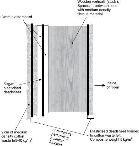
Figure 5.1 Acoustic control wall
The reason for the multiple layers of different materials is because different materials and techniques absorb by different means and are effective in different locations and at different frequencies. Large panel absorbers, made out of plywood for example, can produce high degrees of absorption, but they will tend to do so at specific frequencies, as they are tuned devices. Obviously, to absorb a wide range of frequencies by such techniques we would need to have many absorbers, but we may have problems finding sufficient space in the room to site them all.
If we lower the Q of the absorber, by adding damping materials, we will reduce the absorption at the central frequency but we will widen the frequency range over which the absorber operates. We can therefore achieve a much better distribution of absorption by filling a room with well-damped absorbers than by filling it with individual, high Q absorbers, in which case the absorption in any given narrow band of frequencies would be localised in different parts of the room. Another advantage of lower Q absorbers is that the resonances within them decay much more rapidly than in high Q absorbers. Resonators of a highly tuned nature, as mentioned in Chapter 4, absorb much energy rapidly, but tend to ring-on after the excitation signal has stopped, and hence may re-radiate sound after an impulsive excitation.
The ceiling can be dealt with in precisely the same manner as the walls, but, given the 9–10 m minimum span across this room, joists of either steel or plywood sandwiches would seem appropriate. A typical plywood beam cross-section is shown in Figure 5.2. The only significant difference between the wall and the ceiling structures would be on the inside, as shown in Figure 5.3, where the PKB2 or similar material could be placed in arches between the joists. By now, though, we will have taken the acoustics of the room somewhat to the dead side of neutral, so now we must proceed to rebuild a desirable amount of life into our over-controlled space.
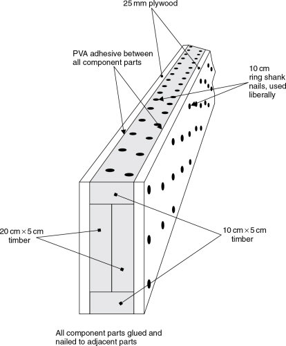
Figure 5.2 Plywood beam construction. A 30 cm × 15 cm beam of immense strength
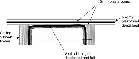
Figure 5.3 Ceiling construction
A studio room is an instrument in itself, so what we have by now managed to do is to destroy an instrument. But, faced with such an initially troublesome isolation shell, such as a room of these dimensions might be (15 m × 10 m × 5 m), it is at times prudent to acoustically destroy it, and then re-build it predictably. With troublesome dimensions the unwanted acoustic characteristics can be difficult to remedy by simple conventional means, and time and experimentation can be needed to assess the remedial work. For this reason the initial acoustical destruction of a problematical room is often a wise choice.
In fact, the principal problem remaining in the room described above would be the incomplete control of the 200–500 Hz region due to the hard floor being in close proximity and parallel to the ceiling. To subdue this problem, panels could be fitted as in Figure 5.4, along with a hanging absorber along one wall, as shown in Figure 5.5. By this stage we would not have a neutral room in the recording sense, but rather, given the reflective floor, we would have something very much approaching a hemi-anechoic chamber, with a small amount of well-damped low frequency modal energy. Such a room would be excessively dead for most music recording purposes, although it could be an excellent basis for certain types of highly damped control rooms. (See Chapter 16 and Appendix 1.)
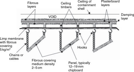
Figure 5.4 Typical ceiling absorption system
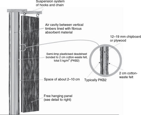
Figure 5.5 Flanking absorbers, similar to those in Figure 5.4 but hung vertically
In the case of the studio room which we are seeking to build here, we need to create an acoustic which enhances the sound of the instruments without unduly announcing its own presence. We need a room which, as far as possible, favours all notes reasonably equally, neither producing ‘wolf’ notes, which stand out due to their coincidence with room resonances, nor causing other notes to have to be ‘forced’ to fight their suppression. The room should have a sonic ambience in which as wide a range of musicians as possible feel comfortable, both in themselves and with their instruments. Such a room would allow a wide range of choice for the recording engineers in the positioning of microphones. It would also allow a great deal of freedom in the positioning of the different musicians, either for the purposes of improved eye-to-eye contact (which can be very important to them) or for purposes of acoustic separation. However, the wall and ceiling absorbers which we have proposed thus far to overcome the room problems would be rather too absorbent for our requirements of ‘neutrality’. So, after controlling the room, we will have to selectively brighten it up, by means that we shall explain shortly. Before doing so, however, perhaps we can briefly digress, in order to look more closely at what we shall be seeking to achieve, and why.
5.3.5 Relative Merits of Neutrality and Idiosyncrasy
Neutral rooms are flexible rooms in which work is usually quick and comfortable. An ensemble placed in a neutral room will tend to be heard and recorded with the natural predominances of that ensemble, with the room favouring neither any instrument nor position to any significant degree. However, if this were the be all and end all of recording, this would be a very short book. Neutral rooms are not the best rooms for all purposes, a point which was perhaps first discovered, at least partially, by accident. There are many studios which have rooms which were no doubt intended to be neutral, but which have failed to realise their goals. From time-to-time, a resonance in such a room, or a certain characteristic pattern of reflexions, can produce an enhancement of certain types of music and instruments played in them. They can become great favourites for certain types of music. The same is true for the stages of certain concert halls, and indeed of other halls which have not necessarily been specifically designed for musical performance. Unfortunately, in many of these, a characteristic of the room which enhances the music may only do so in certain keys or at certain tempos, where the frequencies of resonance or the timing of the reflexions are appropriate, but this means that their suitability for a wide range of recording becomes more limited.
For example, a symphony played in E major may well be strongly reinforced by a room resonance when certain parts are played with gusto. Perhaps if the coincidence is very fortunate, the main characteristic reflexion patterns will have a natural timing which will produce a powerful effect if they coincide closely with a simple fraction of the beats per minute of the tempo. Such a room may give inspiration to the musicians, not only sonically lifting the music but also encouraging a more enthusiastic performance. These rooms can have their places in both the recording and performing worlds in a way which a neutral room may never achieve, but though these rooms may achieve great results in a case such as that stated above, an orchestra performing a symphony in a different key, and with a different tempo, may have difficulties with the room. If played in the key of F sharp major for example, the resonances around the E may be entirely inappropriate, causing emphasis to notes which should not be emphasised, and masking and weakening the notes which the conductor would prefer to be dominant. In such rooms, for every peak in the response, there will be a dip elsewhere. Furthermore, any series of ill-timed reflexions (echoes) may create confusion and a degree of difficulty with the natural flow of the music. Not all musicians may fully realise what is going on, but many may comment on how they just cannot produce their best in that room with a given piece of music.
This is one of the reasons why much classical music is still recorded outside of studios, either in concert halls (with or without an audience), or in town halls, churches, or similar locations. It gives a choice of ambience for the producer, engineer and conductor to try to achieve the ‘ultimate’ from selected performances in selected locations. On the other hand, except for some very highly specialised recording companies, moving to a different location for each piece of music of less than symphonic length would be financially ruinous. What is more, if recording in one location, choosing an idiosyncratic studio for the main piece would perhaps seriously compromise the remainder of the album. Such is one very important reason why neutral rooms are so widely used in the parts of the recording industry where high quality recordings must be able to be made on a predictable, rapid, and reliable basis. They are especially useful for broadcast studios, where good quality recordings must be made quickly and at reasonable cost, as they are perhaps intended for a once only transmission.
The next step in the design of our neutral room is therefore how to add into our relatively dead shell as many desirable features as possible, with as few problems as possible. The major pitfalls to be avoided are erratic changes in the reverberation time/frequency characteristic, bunched echoes in terms of their temporal spacing, and strong highly directional echoes (reflexions). Figure 5.6(a) shows the typical sort of reverberation response that we are trying to avoid, and Figure 5.6(b) the response which is more in the order of what
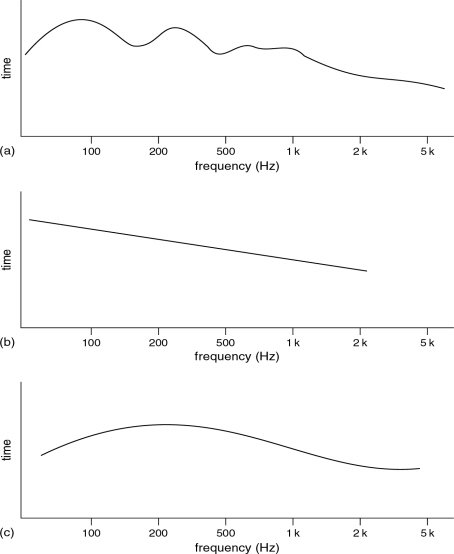
Figure 5.6 Decay responses (reverberation). (a) Undesirable irregular decay response. This type of curve will cause colouration of the recordings. The humps in the curve are due to room resonances. (b) Smooth, desirable decay responses showing freedom from resonant colouration. (c) This plot would be typical of rooms with less LF energy
we are trying to achieve. The response of (a) shows humps in the curve which are characteristic of unwanted resonances. The peaks are the frequencies which will continue to resonate long after an instrument has stopped playing, and the dips represent notes which may appear weak. The irregularities will therefore favour certain notes, suppress others, and mask many low level details of the sound. Such responses at low frequencies are often the result of large, parallel, reflective surfaces which can support the strong axial resonances. It was stated earlier that the angling of the walls away from parallel would help to redistribute the energy in the axial modes, but at low frequencies the behaviour of sound waves is not always obvious.
In order to reflect at low frequencies, surfaces need to be of a size comparable to a substantial proportion of a wavelength, or the acoustic wave will tend to engulf them and pass around. In our neutral room, we can therefore avoid low frequency resonance problems by placing any necessarily large, reflective surfaces, such as large glass doors or windows, in positions where they do not directly face each other. Other reflective surfaces, necessary for the addition of life to the middle and high frequencies, can be arranged such that they have gaps between them, the gaps being at intervals of less than half a wavelength of the highest of any troublesome resonances. Alternatively, they can be arranged with suitably random spacing.
5.4 What is Parallel?
The term ‘parallel’ in its acoustic sense is very frequency dependent. Figure 5.7 shows two reflective walls, each 10 m long and spaced 10 m apart. They are geometrically parallel, and hence are also acoustically parallel at all frequencies. A clap of hands at point X will generate a sound containing very many frequencies, and the sound will propagate in all directions from the source. The waves impinging on points ‘Y’ and ‘Z’ will be reflected back through the position of the source, and will continue to ‘bounce’ backwards and forwards in the form of slap (flutter) echoes along the line ‘Y–X–Z’. Frequencies whose wavelengths coincide with whole fractions of the distance between Y and Z will go through positive and negative pressure peaks at positions in the room which coincide on each reflexion. A musical instrument will drive many of these resonant modes, which strongly reinforce each other. They will tend to be audible in some points in the room close to the antinodes, but not in others, closer to the nodes. A 70 Hz standing wave pattern is shown in Figure 5.8. The light areas show regions of low pressure changes, where the waves would be inaudible, and the dark areas show the regions of high pressure changes, where the 70 Hz content of the sound could be clearly heard.
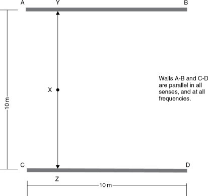
Figure 5.7 Geometrically parallel walls. A sound, emanating from point ‘X’ will spread in all directions. However, the sound waves travelling in the directions of points ‘Y’ and ‘Z’ will reflect back along the line of their original travel, and will continue to reflect backwards and forwards along the same path, creating flutter echoes, until their energy is finally dissipated by losses in the walls and the air. Such are the paths of axial modes, which, when wavelengths coincide with whole fractions of the distance between the walls, produce modal resonances – see Figure 5.8
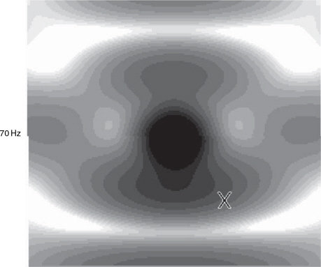
Figure 5.8 Pressure field between parallel walls, 10 m apart. Magnitude of pressure field due to a point source between the two walls depicted in Figure 5.7
If we now angle one wall in a manner shown in Figure 5.9, with one end swung in towards the other wall by 1.5 m, we will have two walls with a 15% inclination. Now, a handclap at point X will again send a wave in the direction of Y, which will return to the source point as a reflexion, and will continue on to point Z. A direct wave will also propagate to point Z, and both the direct and reflected waves will reflect from point Z, not back towards point Y, as in the case of the geometrically parallel walls, but towards point F. They will then reflect to point G, and on to point H. Unlike in the case of the geometrically parallel walls in Figure 5.7, a person standing at point X will not hear the chattering echoes, and most of the resonant energy of the room modes will be deflected into the tangential type, taking a much more complicated course of reflexion. However, whilst the higher frequencies will be deflected along the pathways Y–Z, Z–F, F–G, G–H, at lower frequencies, where the wavelengths are long, axial modes may still persist. This suggests that at low frequencies, the walls must still be parallel in an acoustical sense.
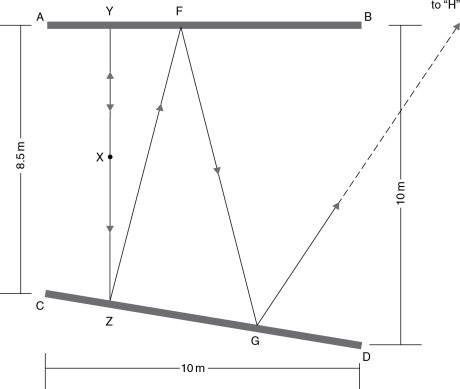
Figure 5.9 Here, the general situation is that of Figure 5.7, except that one of the reflective surfaces has been moved, to create a geometrically non-parallel arrangement between the surfaces A–B and C–D. Flutter echoes, as produced by the surfaces in Figure 5.7, are not possible, as the reflexions will not follow repeating paths. Sounds emanating in the Y and Z directions, from position X, will subsequently follow the path Z, F, G, H, etc. At low frequencies, however, things may not be too different from the conditions of Figure 5.7 – see Figure 5.10
Figure 5.10 shows the 70 Hz standing wave pattern with one wall angled to the same degree as that shown in Figure 5.9. The pattern is remarkably similar to the one shown in Figure 5.8. Although Figure 5.9 shows that the angling of the walls has produced a very different path for the handclap echoes, and will be quite dispersive at high frequencies, at low frequencies very little has changed. Essentially, for geometric angling to be acoustically effective, the path length differences for subsequent reflexions must be a significant part of the wavelength. With the wavelength of 50 Hz being about 8 m, the degree of angling required to be acoustically non-parallel would perhaps be possible in buildings the size of concert halls, but would be likely to consume too much potentially usable space in a conventional recording studio.
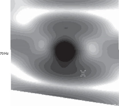
Figure 5.10 Pressure field between acoustically non-parallel walls. Magnitude of pressure field due to a point source between the walls depicted in Figure 5.9
The effect of a limited degree of wall angling on the response of a room is shown in Figure 5.11. The two traces show the performance of the walls shown in Figures 5.7 and 5.9. Above 200 Hz, the non-parallel walls show a clear reduction in modal energy when compared with the parallel walls, but below about 80 Hz there is little difference between the two traces, confirming that, in the acoustic sense at least, the walls of Figure 5.9 are still parallel. The reduction in modal energy above 200 Hz is largely due to the fact that the wall angling drives more of the higher frequency modes from the axial to the tangential type. The tangential modes not only have more complicated paths to travel, but also strike the walls at oblique angles, which tends to rob them of more power than is lost in the more perpendicular impacts of the axial modes. It can thus be seen that whilst the angling of walls can have a very worthwhile effect at frequencies above those which possess a wavelength which will be subsequently shifted in position by a half wavelength or more on their return to the source wall, at frequencies below these, the effect will simply be that of a comb filter, as shown in Figure 5.12. Here, as the frequencies are swept downwards from the above half wavelength frequency, the sweep passes through alternately constructive, neutral and destructive regions. Strong comb filtering at low frequencies is usually musically disruptive and very undesirable in recording studios, and music rooms in general, though it exists to some degree in all reflective spaces. At higher frequencies our ears use it for many beneficial purposes, such as localisation and timbral enrichment.
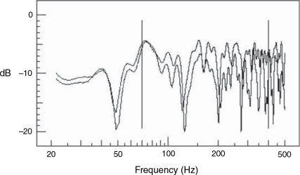
Figure 5.11 The above plots show the response at point X in Figures 5.8 and Figures 5.10. It can be seen that, at frequencies below around 80Hz, the effect of the angling of one of the reflective surfaces has had only minimal effect. Above about 200 Hz, however, the effect is quite pronounced
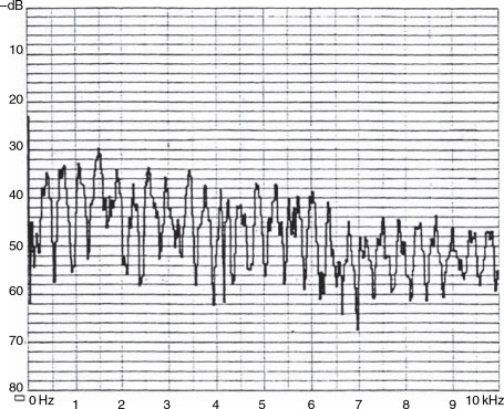
Figure 5.12 The averaged power spectrum of a signal with one discrete reflexion. Comb filtering is revealed clearly on a linear (as opposed to a logarithmic) frequency scale, where the regular nature of the reflexion-produced disturbances can clearly be seen. In the instance shown above, the additional path length of the reflected signal over the direct signal was just under 1 m, producing comb filtering with dips at a constant frequency spacing of just under 400 Hz. A glance at Figure 11.7 will show the response from a more perfect reflector, from which the origin of the term ‘comb filtering’ will be readily apparent
So, whilst the angling of reflective surfaces is a viable technique for reflexion control at middle and higher frequencies, at low frequencies, geometric solutions are usually not able to produce the desired results, and hence absorption must be resorted to, though diffusive techniques are beginning to become a practical reality. (These will be discussed later in the chapter.) Parallel surfaces also produce the repetitive chatter or ‘slap-back’ from impact noises, somewhat akin to the ever-decreasing images seen when standing between two parallel mirrors, and this reflective chatter can be equally as undesirable as the resonant modes in their destructive effect on the music. In the following sections, we shall begin looking at practical solutions for the circumvention of these problems, whilst producing a desirably neutral acoustic.
5.5 Reflexions, Reverberation and Diffusion
We are now faced with the problem of how to put the ideas so far discussed into a practical form. Unfortunately, there are so many ways of doing this that a whole book could be filled on this topic alone, so we will have to take an approach which will incorporate a number of solutions in one design. From this, hopefully, it will be possible to gain something of a feel for the range of possibilities open to designers, and the way that these can be put into general recording practice. What is necessary for musical neutrality in rooms of the size under consideration here (750 m3) is a reverberation time (or, more correctly in these cases, a decay time) in the order of 0.3 to 0.6s, perhaps rising to 0.5 or 0.8 s at low frequencies, with the rise beginning gradually below 250 Hz. Figure 5.13 shows a typically desirable frequency/time decay response of such a room; the time indicated being that taken for a sound to decay to 60 dB below that of its initial steady state level.
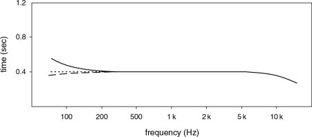
Figure 5.13 RT60 of a good neutral room. Low frequency reverberation times can be allowed to vary with room size
There are two general techniques involved in creating reverberation in such a room; either by reflexions or by diffusion. In recent years, companies such as RPG4 in the USA have created a range of acoustic diffusers capable of operating over a wide range of frequencies. These are constructed on principles based on sequences of cavities whose depths alternate according to strict mathematical sequences. They can be made from any rigid material, but perhaps wood, concrete and plastics are the ones most frequently encountered. The mathematics were initially proposed by Professor Manfred Schroeder5–8 in the 1970s, and are based on quadratic residue sequences. The effect of the cavities of different depth is to cause energy to be reflected in a highly random manner, with no distinct reflexions being noticeable. The random energy scatter creates a reverberation of exceptional smoothness. By using such diffusive means, the overall reverberation time can be adjusted by the ratio of diffusive surfaces to absorbent surfaces, though for an even distribution of reverberation in the room a relatively even distribution of diffusive surfaces is required. Except for the floor and windows, all other surfaces are usually available for diffusion.
With the availability of diffusers, achieving the desirable degree of ambient neutrality may well at first seem to be a simple matter of adding diffusers until the desired reverberation time is achieved, but from such a room there would usually be a lack of musicality. What such a room would lack are discrete reflexions. Fortunately, they are easily introduced, as they are of great importance to both the musicians, and their audiences. On concert stages, they are needed by the musicians to reinforce the sound of any instrument or ensemble. As mentioned earlier, reflexions divide into two groups, late reflexions and early reflexions. The early reflexions, arriving less than 30 or 40 ms after the direct sound, are heard by the ear as a timbral enrichment of the instruments. The later reflexions, arriving 40 ms or more after the direct sound, add spaciousness to the sound, which for many types of music is essential for its enjoyment.
The dimensions of our example of a large neutral room were chosen such that an instrument in the centre of the room would produce only late reflexions from the wall surfaces, but of course, from the floor and ceiling, the reflexions would necessarily be of the early type. Instrument to floor distances are normally relatively constant; floor reflexions typically being in the 5 to 10 ms region. Any ceiling reflexions in this room would be in a borderline 20 to 40 ms region, dependent not only upon ceiling geometry, but also upon whether diffusive, reflective or absorbent surfaces predominated. In later chapters dealing with more reverberant spaces we shall look at reflexions further, but in the neutral type of room under discussion here, whatever reflexions exist should tend to be reasonably well scattered, otherwise they will develop a character of their own and the room would lose its neutrality.
5.6 Floor and Ceiling Considerations
Let us now look at possible ceiling structures for our neutral room. As we discussed earlier, the nature of the floor has been chosen to be wood. Carpet tends to produce a lifeless acoustic, uninspiring for the musicians and unhelpful for the recordings. Stone was rejected, partly for its ‘harder’, more strident reflective tendency, but also on the practical ground of slippage. Floors of neutral rooms overwhelmingly tend to be of wood. At this point of the design stage (see Figure 5.3), we have a relatively dead ceiling at a height of about 4.5m. We cannot come down too much below this because the reflexions which we would introduce would tend to become of the tone colouring, early nature. What is more, too low a ceiling would preclude the siting of microphones above the instruments at a height which may be necessary to cover any given section of musicians.
One solution to such a problem is to construct a ceiling of wooden strips, with spaces between them which would allow a good proportion of the lower frequencies to pass into the absorbers behind. They would therefore provide mid and high frequency reflexions without allowing an unwanted low frequency build-up. As mentioned earlier, in order to reflect at low frequencies, surfaces need to be of sizes comparable to the wavelengths to be reflected. We can therefore have some degree of control over the lower limit of our desired reflectivity by providing gaps in our reflective surfaces at appropriately chosen intervals. This alternative juxtaposition of reflective and absorbent surfaces will also produce significant diffusion (see Section 4.7), which in many instances is extremely useful.
Once again with this complex subject there are so many ways of achieving each objective, so here we will only be able to look at some of the possibilities within one technique of specific interest. The strips described could be of hardwood or softwood, and could be plain, varnished, painted, rough or smooth. Each will give its own subtle character to the sound. Hardwoods, untreated, can be quite interesting sounding, but in today’s ecological climate many designers refuse to specify any woods of an exotic or not too easily replenishable nature. Sound is of course important, but there are also environmental considerations which we cannot escape.
Obviously, we do not want to encourage the build-up of resonant energy in any modes which would unpleasantly colour the sound, so the ceiling surface can be broken into a series of angled sections, set to produce what the designer would consider to be the most appropriate angle for reflexions. A selection of possibilities for ceiling designs are shown in Figure 5.14. Figure 4.33 showed a pattern of wood/space ratios which are based on a numerical sequence, not dissimilar to the one used for the diffuser cavities referred to earlier. This type of arrangement could also be used, though perhaps it would be a little tricky to find a suitably attractive way of mounting the lights. The purpose of all these arrangements, however, is to help to prevent any noticeable patterns forming in the reflected sound-field.
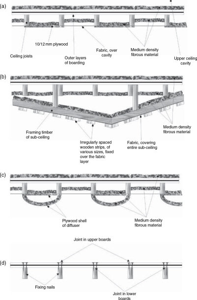
Figure 5.14 Various ceiling constructions for a neutral room. (a) Alternative hard and soft surfaces. (b) Irregular hard/soft surfaces. (c) Absorbent spaces and curved, diffusive surfaces. (d) Fixing arrangement of plasterboard sheets, with overlapping joints above the beams
The BBC9 (British Broadcasting Corporation) have developed a very successful range of ceiling tiles which fit into the typical sort of false ceiling structures used in many offices and broadcast studios. In fact, using a steelframed grid for a false ceiling allows great flexibility in the introduction of easily replaceable absorbent, reflective or diffusive tiles, which can be an excellent way of providing a room with a degree of acoustic variability. In the broadcasting world, these systems are widely used, but in commercial music recording studios their appearance is generally considered to be too industrial to provide the necessary decorative ambience for musicians to feel comfortable and creative. However, these things are highly personal, and for people who find these prefabricated tiles pleasing to look at they can be safe in the knowledge of their excellent acoustical performance.
5.7 Wall Treatments
Figure 5.15 shows a possible wall layout for our neutral room, and it can be seen that parallel wall surfaces have been avoided. At frequencies for which the walls are still effectively acoustically parallel, the acoustic waves are allowed to pass into absorbers, either directly, or after first reflexion. Care has been taken to make sure that windows and doors do not face directly towards any parallel reflective surfaces. In the room shown, the control room door and window systems are set into a relatively absorbent wall, so one of the walls is now defined.
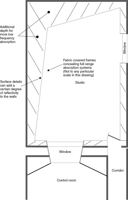
Figure 5.15 Possible layout of neutral room
That now leaves us with three wall surfaces to complete. For musical neutrality, we do not want too much reflective or reverberant energy, but just enough to give the room sufficient life to stop the instruments from sounding too dead. It is similar to a little seasoning bringing out the flavour of the food without overpowering it. The glass surfaces, the entire floor, and the ceiling reflexions are more or less enough for this. We also have the problem that if we make the walls reflective to any significant degree, we may create unduly reflective areas for any musicians playing close to the walls. In fact, in the corners of the room, the colouration could become most unnatural if bounded by the floor and two reasonably reflective walls, all providing early reflexions in addition to those from a borderline early/late ceiling.
For reasons of structural integrity, if we have walls covered with fabric for decoration we may need wooden rails, at waist height or a little higher, to prevent people from ‘falling’ through the fabric. We need skirting boards so that the floors can be cleaned without soiling the fabric, and we may also need to put rails at knee height as a convenient mounting for microphone sockets and electrical outlets. Figure 5.16 shows a small version of a room with these fittings, but if such a room should be considered to be a little too dead, or in cases where only a rather small area of glass is to be used, then an arrangement such as that shown in Figure 5.17 can be employed. The reflective surfaces are based largely on the concepts of Figure 4.33, but the ratio of the areas of the spaces to the facing timber can be adjusted to produce the required degree of acoustic ‘life’. The fabric covering is for decorative purposes only, and so should be of a type which is acoustically transparent. Many fabrics can be surprisingly reflective, and if stretched too tight they may also act like drum skins. Lightweight, Lycra-based ‘stretch’ fabrics are useful here, but specialist ‘acoustic’ fabrics, which are normally flameproof, are the most common option.
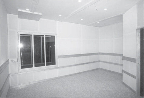
Figure 5.16 A relatively small room with a very neutral acoustic characteristic. Studio room of the Ukrainian Air Force, Cultural, Educational and Recreational Centre, Vinnitsya, Ukraine (1996)
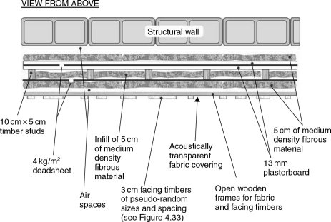
Figure 5.17 Wall structure and treatment for brightening a ‘neutral’ room
So now we have something approximating to a musically neutral room, which tends neither to add character to the sound of an instrument nor ‘suck out’ all of its life. Rooms such as the one being described here, are excellent for recording efficiently, rapidly and predictably, but if they are the only spaces available for recording, then the practice still harks back to the philosophies of yesteryear and their more ‘technical’ correctness. Nonetheless, these rooms can still be very useful, and they are still worthy of consideration in many circumstances. Remember that neutral rooms are very necessary in the broadcast industries and in recording facilities where rapid results are necessary from a wide range of music and instruments. For these purposes, they excel. Figure 5.18 shows a room which may be quite neutral on a macro scale, but which provides local areas of different acoustics.
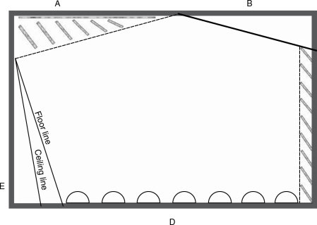
Figure 5.18 Possible layout of a neutral room with a little flexibility. (Doors and windows omitted for simplicity.) The ceiling could be typically one of those shown in Figure 5.14. The walls: (A) Low frequency absorber with controlled upper mid/high frequency reflectors. Similar surface features to those shown in Figure 5.17. (B) Wood-panelled, reflective walls. (C) Wide-band absorber, faced with fabric covered frames. (D) Diffusive wall, with absorbers between diffusing half-cylinders. (E) Reflective, double-sloped wall, faced with wooden panelling
5.8 Small and Neutral
Until now, we have been discussing the treatment of a room of 650 m3, which by the standards of the current trend of recording studio building is verging on the huge. A question much more frequently asked today is how to get a degree of neutrality in a room of much more modest proportions, even to the degree of only beginning in a space of 40 m3 or less. Now that is a challenge!
When listening to recorded music, and especially on headphones, one frequently becomes aware of the sound characters of the rooms in which many of the recordings were made. In itself this should not be a problem, unless the room sound is ‘boxy’, or inappropriate to the song or the rest of the instrumentation. Unfortunately though, this is all too often the case, as the vocals have either been recorded in a small ‘vocal booth’ to achieve the desired separation from the other instruments, or they were recorded in a small room of insufficient neutrality, perhaps because of convenience or the lack of a better option. The reason could also possibly have been because no large or neutral rooms were available. (Sadly, this is very often the case.)
What is also unfortunate is that far too many control rooms and/or monitor systems are insufficiently neutral in themselves to allow the recording staff to notice the subtleties of the vocal room acoustics. This is especially the case in many multi-media or ‘project’ studios, where due attention to control room monitoring conditions has often been seriously lacking. Small recording room acoustics often have decay times which are less than those of most control rooms, hence the sound of the recorded room becomes lost in the monitoring acoustics of the control room. In other cases, the staff of a studio can become so used to the sound of a small recording room that they no longer hear it in the background of their recordings. The problem is perhaps now greater than it used to be, as the lower noise floors of digital recording systems have rendered audible (even in the home) sounds which would in earlier years have been lost in the background noise. Ironically, it is also often this digital recording equipment that produces so much mechanical noise in the control rooms that very few of the noises or unwanted sounds on the recordings can be heard, as mentioned in Section 1.2.2.
Where neutrality is required, vocals are usually best performed in the middle of large rooms, where there are few early reflexions. If floor reflexions are a problem, then rugs can always be provided for the vocalists to stand on, and this also helps to reduce the pick-up of the sound of any foot movements. However, most of the vocal energy usually tends not to be directed towards the floor and so very little returns to cause problems. What is more, the selected microphone patterns are usually either cardioid or figure of eight, and hence naturally tend to ignore the floor reflexions. Purpose designed vocal rooms usually need to be as neutral as possible unless the acoustic liveliness of a room is being used for effect.
The problem with using live rooms for vocals is that, usually, the nature of the room ambience that is considered good for instruments is not an ambience that does much good for voices. In large neutral rooms, the space around the microphone is usually conspicuous by the absence of any early reflexions which can colour the sound, but in small rooms, this is not so easily achieved. The problem with small rooms is that all reflexions are of the sound-colouring early type, and the spacious sounding late reflexions cannot exist. A general neutrality is difficult to achieve in small rooms, and especially so in very small rooms of the size commonly associated with vocal rooms. In circumstances where no large room is available it is perhaps better for vocal recordings to be made without any room ambience whatsoever, except perhaps for the reflexions from the floor and a window, which, as we have just discussed, most typical microphone techniques would ignore. A further difference between the recording of vocals and the recording of many other instruments is that there is an intelligibility factor to be considered. Many vocal subtleties would be rendered unintelligible in rooms where insufficient ‘space’ existed around the vocal sound before the reflexions returned to the microphone.
Furthermore, in small rooms there is little space to mount typical low-frequency acoustic control devices, and simple treatment of a bare shell will do little to create a neutral sounding environment. Simple attempts at absorption by the placing of acoustically absorbent tiles on the walls and ceiling will not suffice. These will tend to absorb the higher frequencies but leave the lower-mid and low frequency modes largely untouched, yielding a room with a heavily coloured ambience which will lack life and add a thickness to the sound, robbing it of much clarity. Rolling out the offending frequencies by equalisation will take the lower frequencies out of the unwanted ambience, but it will also take them from the direct sound of the voice. In turn, this will disturb the natural harmonic structure, and may tend to remove much of the power and body from the sound. Unfortunately, to make a very small room musically neutral is virtually impossible, so, in the vast majority of cases, the only thing to do with a small room is to try to absorb everything, and then provide a few discrete reflexions. The required ambience may then have to be added artificially.
If we make the room too dead, the musicians may find it uncomfortable on first entering the room. In almost all cases they will wear headphones when recording, but nonetheless their initial impressions when entering the room can have lasting effects. They should never be allowed to feel uncomfortable, even if only for the few seconds between entering the room and putting on the headphones, as it is remarkable just how those few seconds can leave many musicians unsure of their sounds. Illogical it may well be, but artistic performances tend to be fragile things, and anything which runs the risk of introducing any extra insecurity into musicians is to be avoided. Fortunately a hard floor and a window, or glass door, can usually provide sufficient reflective life to avoid the musicians experiencing an anechoic chamber effect when they enter the room, and this is easily achievable without creating a boxy character.
5.8.1 Practical Constructions
Figure 5.19 shows a layout for a neutral-to-dead vocal room which only occupies about 9 m2 of floor area and 3 m of height. It assumes a ‘worst case’ structural shell of what is more or less a 3 m cube. In many cases such rooms are not only used for singing but can also be used for voice-overs or dialogue replacement. In these cases there may be no music to mask any extraneous noises, so the room should be well isolated. In the case of Figure 5.19, which is based on the design of a very successful room, one wall adjoins a control room, and the other surfaces are all concrete. The whole structural shell was first lined with a 6 cm layer of reconstituted polyurethane foam of 80 kg/m 3density, except for the floor, where a 3 cm layer of a 120 kg/m3 foam was used to avoid the problems shown in Figures 3.6 and 3.7. Incidentally, vocal rooms of the type being described here do tend to be excellent for the recording of bass guitar amplifiers, especially if a sound with tight impact is being sought.
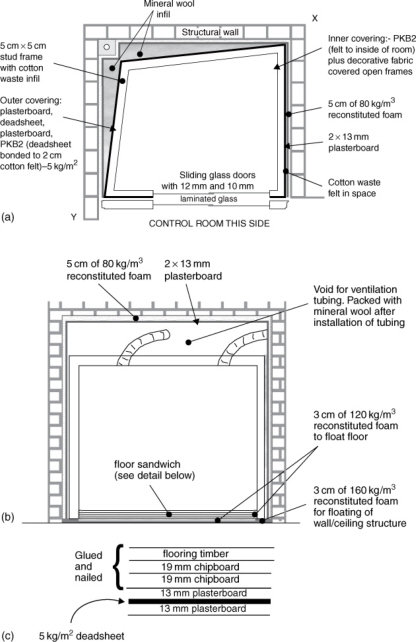
Figure 5.19 Construction of vocal room. (a) Plan, (b) elevation, (c) floor sandwich
The polyurethane foam lining of the walls and ceiling was secured by contact adhesive. In turn, the foam was then lined with two layers of 13 mm plasterboard. This type of combination, mass/spring/mass (plasterboard/foam/ wall) is ideal here as it serves two purposes. First, it provides a good degree of broadband sound isolation. Second, it also provides a good degree of low frequency sound absorption. Therefore, it acts like a reasonably good combination of our open window and brick wall from the previous chapter. However, this system largely achieves by internal absorption what the wall and window do by reflexion and transmission, albeit not so effectively. The internal, acoustic control ‘box’ was constructed on a higher density foam which was first placed on the floor. The walls and ceiling structures were similar in nature to the ‘neutralising’ acoustic shell described in Section 5.3.4. If the space between the inner, floated room structure and the foam/plasterboard isolation treatment is lined with a fibrous, medium density material, we can then incorporate the properties of fibrous absorption to prevent any resonances from developing in the gap. We can thus combine relatively high absorption, good isolation (low transmission) and relatively low reflexion, all from the same composite lining. This is important because in such a small room we do not have sufficient space for large, conventional, wideband absorber systems.
So, perhaps we can now consider the progress of a sound wave as it leaves the mouth of a vocalist and arrives at the room boundaries as shown in Figure 5.19. Remember, we want this room to be sufficiently dead to give no recognisable sound of its own to the recording, but to have just enough life to prevent the room from making the vocalist feel uncomfortable when entering it.
5.8.2 The Journey of the Sound Waves
The sound waves expand from the mouth of the vocalist in a reasonably directional manner. Except at the lowest frequencies, this fact becomes self-evident upon working in these rooms. Another person becomes remarkably quieter if he or she should turn away from the listener, unless they turn to face the reflective glass doors or the floor. In most cases, the musicians will be facing glass doors or windows, as visual contact with the control room is usually required for operational purposes. The sound will leave the mouth and strike the glass, which will reflect at least 95% of the energy back into the room with a very wide angle of dispersion. Without headphones, the musicians will hear this, plus any reflexions from the floor, which may either be direct or also via the window. These reflexions will help to alleviate any sense of being in an oppressively dead room.
Energy reflecting back from the glass will strike the two side-walls and the ceiling with an oblique angle of incidence. Only the wall opposite the glass will receive any sound at perpendicular incidence. The oblique arrival of sound at the face of an absorber will usually cause a much greater loss of energy, as it must pass through the absorbent material in a diagonal manner, and thus effectively travels through a thicker section of material (see Figure 5.20). Any sound reflecting from the window and the floor will automatically then pass into the walls at oblique angles. If a cardioid microphone is placed between the musician and the window, facing the vocalist, it is only capable of receiving sound directly from the musician’s mouth, plus, perhaps a minute amount of the floor reflexions.
The sound which passes into the first layer of felt behind the decorative fabric surface will be partially absorbed, but some will continue through to reach the deadsheet backing. At medium and high frequencies the deadsheet is reasonably reflective, but any high frequencies reflected from it, even at Incident wave ‘B’, striking at a shallow angle, would pass through approximately 10 cm of the absorbent material. For materials of random texture, the absorbent effect is correspondingly increased in proportion to the extra distance travelled through the material. It should be noted, however, that for certain types of material with a pronounced directionality of fibres or pores, the above case may not apply. In general, however, oblique strikes will suffer more absorption than perpendicular strikes 90 degrees incidences, will still have to pass once again through the felt in order to re-enter the room. For wavelengths in the order of 8 cm (4 kHz) 2 cm of fibrous absorption will be highly effective, as the internal passage of sound through felt at relatively short wavelengths is tortuous. In fact, due to the oblique angles of incidence for many of the reflexion paths, quite high absorption could be expected down to 2 kHz, or below. If only 10% of mid and high frequencies were reflected from the surface of this vocal room on the first contact with a wall, then the second strike would only reflect 10% of that 10%. By the third bounce, which in such a small room may only take 15 or 20 ms, the energy remaining in the reflexions would only be one thousandth (10% of 10% of 10%) of that leaving the musician’s mouth. It would thus be 30 dB down within the first 20 ms, and 60 dB down in considerably less than 50 ms. This is a very short decay time (T60).
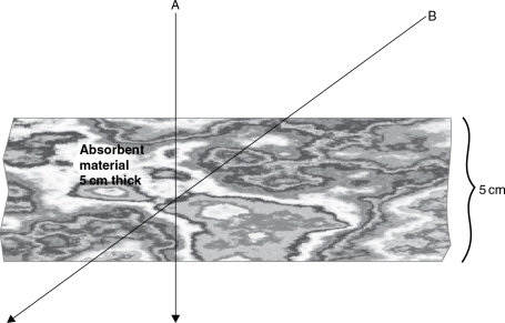
Figure 5.20 Effect of angle of incidence on absorption. An incident wave ‘A’ striking the absorbent material at 90° would pass through the 5 cm thickness of the absorbent material.
At low frequencies, such as those produced if a bass guitar amplifier were to be placed within the room, the mechanisms are very different. The low frequency sounds would propagate omni-directionally, and would possess much more penetrative power than the high frequencies because of the wavelengths being very long compared to the wall thicknesses. The first internal lining of the rooms (behind the decorative fabric) is in this instance a kinetic barrier material (deadsheet) covered in a 2 cm layer of cotton waste felt. The composite weighs just less than 5 kg m2 and comes in rolls, 5 m × 1 m, and this is nailed to the stud framework of the room, felt side to the room. Behind this barrier is an air cavity of 7.5 cm, containing a curtain of the same cotton waste felt material, hung from the top, and cut carefully to fill completely the cross-section of the gap. On the other side of the stud frame is a double layer of 13 mm plasterboard, with a layer of 5 kg/m2 deadsheet sandwiched in-between. As mentioned in Section 5.3.4, the heavier plasterboard layers tend to be effective absorbers around the lower bass frequencies, whilst the membranous deadsheets absorb slightly higher frequencies. See also Figure 4.27.
All of the above layers are diaphragmatic. They are free to vibrate but they are also all highly damped. The room, to the low frequencies at least, presents itself as a large, limp bag. When the sound waves strike the kinetic barrier, it is somewhat like the effect of a boxer striking a heavy sandbag. The room gives, absorbing much of the energy and converting it into heat. Effectively the inner walls get pushed and pulled around by the compression and rarefaction half-cycles of the sound waves, but their inertia and internal viscous losses are such that they are almost incapable of springing back. Linings of this type have low elasticity, they are more or less inert, which is why such materials are known as deadsheets. In a similar way, one could give an almighty blow to a bell made from lead, but one would not get much ring from it. The lead would yield to the blow, and its high internal damping would absorb the impact energy. Its weight would then ensure that it did not move much, and hence if it could barely move or vibrate, it would have difficulty in radiating any sound.
When the sounds vibrate the deadsheet linings of our room, work is done in moving the heavy, flexible mass, and further acoustic energy is turned into heat energy as a result of the damping which resists the movement. Some sound is inevitably reflected back into the room, but with room dimensions so small, in a matter of a few milliseconds the reflected energy strikes another surface, so suffers losses once again. All in all, the sound decays very rapidly, and the low frequencies, below 150Hz or so, are effectively gone in less than 100 ms. The very low frequencies receive no support at all from modal energy, as the pressure zone in a room of such size exists up to quite a high frequency.
5.8.3 The Pressure Zone
Modal support was discussed in Chapter 4, and it was stated that the lowest resonant mode of a room was that for which a half-wavelength would fit exactly into the longest dimension of the room. Once we drop below that frequency, we are entering the pressure zone. If less than half a wavelength can exist within the dimensions of a room, then instead of waves of positive and negative pressure distributing themselves over the room, the whole room will either be rising in pressure, or falling, dependent upon whether it is being subjected to a positive-going or negative-going portion of a long wavelength. The frequency below which the pressure zone will exist is given by the simple equation:
| (5.1) |
where
fpz = pressure zone upper frequency
c = speed of sound in metres per second (344)
Lr = longest room dimensions, in metres In the case of the room under discussion here, the maximum room dimension between reasonably parallel surfaces is about 2.5 m, therefore:
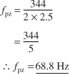
There could thus be no modal support in this room below 68 Hz, and the heavily damped lowest mode would be the only supportable mode within the first octave or so of a bass guitar. The response could therefore be expected to be very uniform. (See Chapter 6, Figure 6.11 for a representation of the pressure zone.) We will return to the subject of the pressure zone in later chapters, because its effect on loudspeaker response can be considerable (Section 13.5).
5.8.4 Wall Losses
When this internal bag inflates and deflates, it does radiate some power outwardly, but the nature of the construction of the room is such that the air cavities created between the vertical studs and the outer and inner linings provide further damping on the inner bag. The air will tend to resist the pressure changes, as its elasticity will apply a restoring force on the inner bag. In turn, it will also exert a force on the outer composite layer of plasterboard and deadsheets. This layer is also very ‘lossy’ and heavily damped. The internal particles in the plasterboard turn acoustic energy into heat by the friction of the particles rubbing together, and additional work is done by the need to move such a heavy mass. The sandwiched deadsheet forms a constrained layer, tightly trapped between two sheets of plasterboard. The constrained layer concept, shown diagrammatically in Figure 3.11 and discussed previously in Chapter 3, effectively tries to sheer the trapped layer of viscously ‘lossy’ material over its entire area. The resistance to this sheering force is enormous, so the damping value is high and the acoustic losses are great.
The transmission from the inner layer to the outer layers of the stud wall is partially due to the common studwork (vertical timbers) to which both surfaces are connected. This usually creates no problems as long as the inner surface is of a limp nature. Its lack of rigidity does not provide an effective acoustic coupling to the studs, and its weight, in turn, helps to damp the stud movement. The direct energy impacts on the studwork itself, where the deadsheet is fixed to it, and hence where that deadsheet is effectively more rigid, is only a small proportion of the overall surface area. If the studs are 5 cm in width and spaced on 60 cm fixing centres, they occupy only 5 cm out of every 60 cm, or about 8% of the surface area. In addition, being of narrow section, the lower frequency waves will tend to pass round the studs. However, if every last dB of acoustic isolation is required, the slightly more complex stud arrangement as shown in Figure 5.21 can be used. Here, the studs are double in number, but are interleaved such that the only common coupling between the two surfaces of the wall are at the top and bottom, which are in any case coupled by a common floor and ceiling. Walls of this type take up an extra 2 cm of space, but if the extra performance is needed, the space penalty is low. Thinner studs could be used if the space was critical, but they would provide less rigidity, and less damping on the panels, and hence may negate some of the advantage gained by the separation.
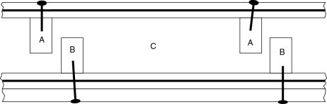
Figure 5.21 Staggered stud system. The sheet layers on each side of a stud wall can be attached to independent sets of studs, connected only by the top and bottom plates ‘C’. By staggering the studs and interleaving them, only a small amount of extra space is consumed compared to that of a conventional stud wall. This system reduces greatly the area of common coupling between the two sets of sheet materials, and usually offers more isolation than the more usual system with common studs. The cavity should be well filled with fibrous material, because resonances in the space can strongly couple the two sheet layers, across the air gap
The majority of the inter wall-surface coupling is in any case through the air cavity. The cavity should be lined with fibrous material, which helps to increase the losses, but at very low frequencies its effect is only minimal. The losses from the air cavity coupling are great as long as the outer surface is very heavy, as it is difficult for a thing of low mass to move a more massive one. It is therefore relatively difficult for the air which is trapped in the cavity to excite the outer composite layer of heavy sheet materials. Historically, some of the first tests of this principle were carried out by experimenting with cannon in the Alps, so as this factor of acoustic coupling is quite an important aspect of our isolation systems, perhaps we should now consider it in a little more detail.
5.8.5 Transfer of Sound between High and Low Densities
In the 19th century, two cannon were placed on the side of a mountain, one low down, but not at the foot, and the other high up. The cannon were charged with equal amounts of powder, and observers were placed not only at each cannon position, but also high up and low down on a mountainside at the opposite side of the valley.10 The arrangement is shown in Figure 5.22. The cannon low down was not placed at the very bottom of the valley so that its sound would not be unfairly reinforced by having the valley floor to push against. When the cannon were fired, the flashes and the smoke were clearly seen from all distant stations, and as the distances to the listening stations were known, the sounds of the cannon were expected to be heard after the appropriate time intervals had elapsed.
Figure 5.22 Nineteenth century cannon experiment. Two identical cannon are positioned at ‘A’ and ‘C’, and charged with equal amounts of powder. When cannon ‘C’ is fired, the observers at ‘A’, ‘B’ and ‘D’ will see the flash almost instantaneously. After a length of time corresponding to the local speed of sound in the air and their distance from C’, the three observers will hear the report from the cannon. When the cannon at ‘A’ is fired, the observers at ‘B’, ‘C’ and ‘D’ will see the flash. After the appropriate time lapse, the observer at ‘B’ will hear the sound, but the observers ‘C’ and ‘D’ in the denser air, may hear nothing, despite the fact that they are closer to ‘A’ than is observer ‘B’
The lower cannon was fired first, the flash was seen, and the three listeners at the distant listening stations, A, B and D, awaited its report, which duly arrived at each position after the respectively appropriate time intervals. In each case, when the sound was heard, the listeners signalled its arrival by means of flags. The sound intensity at each station was described as best as could be done in the days before sound level meters. The sound was heard loudly by the listener low down on the opposite side of the valley, and was clearly heard by the two listeners high up on the two sides of the valley, at positions A and B in Figure 5.22. When the higher cannon was fired from position A, again the flash and the smoke were clearly seen by the distant listeners, this time at positions B, C and D. After the expected time interval had elapsed, the listener at position B signalled that the report had clearly been heard, but after more than enough time had passed for the sound to arrive at positions C and D, no signals were seen, as no sound had been heard.
From this it was deduced that the density of the air in which the sound was produced, relative to the density of the air in which it was heard, was responsible for the efficiency with which the sound would propagate. The explosion in the higher density air, low down in the valley, could easily cause the sound to propagate not only to the listening station D, in the same high density air, but also to the listening stations at A and B, higher up in the lower density air. However, whilst the report from the high cannon could be readily heard at listening position B, which was in the same low density air, the sound could not penetrate effectively into the higher density air at the lower listening stations, C and D. This was despite the fact that position C was closer to A than was position B, where the report was clearly heard. Furthermore, compared to the denser air at the bottom of the valley, the thinner air higher up the mountain provided the explosion of the gunpowder with less air to push against as it left the barrel of the cannon. With less air to push against, less work could be done by the explosion, and hence less work done meant less sound generated. The air pressure reduces by almost 1 millibar for every 8 m that one rises above sea level, and if temperatures are equal, the densities will thus be proportionately reduced. In fact, given the 2000 m vertical separation between the cannon shown in Figure 5.22, the air pressure at the upper positions, A and B, would be less than 75% of that at the lower stations, C and D.
5.8.6 Combined Effects of Losses
It can now be appreciated that the acoustic energy in the vocal room will be severely attenuated by the compounding of the low frequency losses in the deadsheet, the damping loaded upon it by the air in the inter-stud cavities, and the mass of the plasterboard to be moved; damped by the sandwiched, heavy deadsheet. As this whole structure sits on a layer of foam of an appropriate density, it thus sits on a foam spring, and is surrounded on the other five sides by air springs. The radiation of what energy is left must now pass through the ‘springs’ in order to get to the plasterboard layer which covers the foam, which is in turn glued to the structural walls. Springs are reactive; that is they tend to store and release energy, rather than passing it on. The cavity in Figure 5.19 is lined with cotton-waste felt. Any resonances which try to build up in these air cavities, particularly as lateral movement of the waves travelling around the box, must effectively pass through metres of felt, which they patently cannot do. By such means, resonances in the air space are effectively prevented. One acoustic ‘short circuit’ is therefore avoided, because if the air was allowed to resonate, its ability to acoustically couple the two sides of the gap would increase greatly.
The low density air surrounding the inner, floated, acoustic shell must then transfer its vibrational energy to the much heavier plasterboard wall linings. As with the cannon, it is difficult for a low mass of low density material to excite a high mass of high density material, so further transmission losses take place as the mass of the plasterboard resists the vibrations of the air in contact with it. The particles in the plasterboard also provide losses due to their friction, so this reduces even more the energy which can be imparted to the foam to which it is stuck, and which in turn is stuck to the wall.
The foam itself, securely bonded to the plasterboard by adhesive, strongly resists the movement of the plasterboard, so yet again, vibrational damping is provided and even more acoustic losses take place. Finally, the foam, glued to the structural wall, flexes under the force being imparted to it from the plasterboard, because its mass and stiffness are insignificant compared to those of the main structural wall which it is trying to move. The exact effect of this final loss depends mainly on the mass of the wall to which it is attached, but typically, from the inside of the finished room to the other side of a structural wall, at least 60 dB of isolation at 40 Hz could be expected from a structure similar to that being discussed here, though obviously not through the side with the glass doors.
Of course, what we have been considering here on our journey through the complex wall structure are transmission losses, but we should not forget that from each layer boundary, and particularly the inner boundaries of the more massive layers, acoustic energy will be reflected back towards the room. We have four heavy layers in this structure, the deadsheet inner lining, the composite plasterboard/deadsheet sandwich on the outside of the inner box, the plasterboard which is glued to the foam, and the structural wall. We discussed earlier the progress of the reflected wave from the inner lining, but as we pass to the sandwich layer, the reflexions will be stronger due to the greater rigidity of the material. However, these reflexions cannot pass directly into the room. They must first pass through the inner deadsheet layer, which has already attenuated the incident wave due to its mass, its internal viscous losses, and its poor radiating efficiency. The reflexions from the sandwich layer will also suffer similar losses as they seek to pass through the layers on their way back into the room. What is more though, just as some energy of the incident wave is reflected back into the room from the internal lining of deadsheet, the linings will also reflect back into the wall structure, towards the sandwich, a portion of the energy reflected from that sandwich, so we lose energy as we pass through each stage. The more internal losses which we can create within our multi-layered wall, by using internal reflexions to trap the sound within the layers until it dissipates as heat or work done, then the more pure absorption (i.e. not counting transmission) we will be able to achieve.
Similarly, the other heavy boundary layers on either side of our 6 cm foam, stuck to the structural wall, will also reflect energy back towards the room, but the deeper we go through our complex wall structures, the more difficult it will be for the acoustic energy to find its way back into the room. Taken as a whole, such a complex wall structure as in Figure 5.19 deals with the internal acoustic problems and the sound isolation problems by its high overall internal absorption. The structure is progressively absorbent, in that the most reflective layers are those furthest away from the inside of the room. If we remember our open window and brick wall discussion, simple sound absorbing materials tend to be poor isolators, and good isolators tend to be poor absorbers, but in the case of our small neutral-to-dead room we need both good absorption and isolation. The option of placing an adequate amount of a sound absorbing material on the inside of a room, then placing a simple isolation wall outside of it, tends to use enormous amounts of space. Using such simplistic techniques in a space of three metres cubed (the same as the structural space for the room in Figure 5.19) we would end up with a usable space only about the size of a telephone kiosk.
The multi-layered, complex structures described here are much more efficient in terms of the space which they consume. They are also a little like the energy absorbing front ends of motor cars, which crumple gradually on a frontal impact, absorbing the energy of a crash, stage by stage, and preventing it from doing too much damage to its occupants, or to the occupants of the car which it may have run into. Similar principles are now employed in the new, lightweight armour for battle tanks and warships, in place of the enormously heavy, steel armour-plate which was used almost exclusively up to the late 1960s. The similarities here should not be too surprising as, after all, energy absorption is energy absorption, whether it is absorbing the energy of car impacts, shells, or sound waves. However, the impedance differences are great, which is why different materials are necessary in each case.
Well, now that we have dealt with the relatively simple surface treatments which absorb the upper-mid and the high frequencies, and we have discussed the limp bag which so effectively controls the low frequencies, all that we are left with is the low-mid frequencies. These are the modal frequencies, where resonances can develop between the faces of the room surfaces. Their waves are too long to be absorbed by the superficial layers of absorbent felt, but they are not long enough to be fully affected by the deadsheets and composite layers. In the modally controlled region there are two types of mode, the forced modes, which are driven by the sound source but which stop when the sound source stops, and there are the resonant modes, which can continue to ring on at their natural frequency, long after the driving force has ceased. A loudspeaker, when driven by an amplifier, will vibrate at the driving frequencies, but when the drive is disconnected, and if there is little damping, the cone will continue to resonate for a short time as its natural frequencies. The principles in the cases of the room and the loudspeaker are similar.
The problem in terms of the decay time of the room is the resonant modes, the worst offenders of which usually develop between parallel surfaces. In the room of Figure 5.19, no parallel surfaces exist, as the walls have been angled in order to use geometrical techniques to help to prevent modal reinforcement. The amount of angling shown would not be enough in a more lively room, as the lower of the lower mid-frequencies would still see them as relatively parallel in terms of their wavelength (see also Figures 5.8 and 5.10), but in the case of a room lined with so much felt and deadsheet, the gradual, non-perpendicular impacts tend to suffer much greater absorption and much less effective re-radiation than would be the case when striking similarly angled, but more reflective surfaces.
The ceiling structure of this room is similar to that shown in Figure 5.3. It is vaulted with the PKB2 composite deadsheet/felt material, the felt side facing the floor. The 20 cm depth of the vaulting is sufficient to begin to take the energy out of both the direct mid-frequency waves and the ones reflected almost perfectly from the hard floor. As the wooden floor is a better reflecting surface than any of the other surfaces of the room, the design of the ceiling opposing it has to give due consideration to that fact. Above the inner ceiling is a void of about 30 cm in depth. When stuffed with absorbent material, be it fibrous or off-cuts of foam, it provides good absorption of any lower mid-frequencies which may penetrate the inner linings. The ceiling void is actually there primarily for another purpose however; the passage of ventilation ducts, as one does tend to have to provide musicians with a good supply of fresh air, delivered as smoothly and silently as possible. The overall response of the room is very similar to that shown in Figure 5.27 (a), but without the rise below 50 Hz.
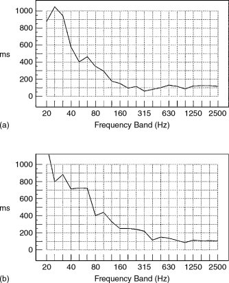
Figure 5.27 The decay characteristics of the rebuilt room shown in Figure 5.26 are shown in (a), whilst (b) shows the decay of the original room, similar to that shown in Figure 5.24. Note the lumpy, roller-coaster appearance of (b), a sure indication of the existence of resonances in the 63Hz to 400Hz region. This contrasts with the smooth curve through the same region in the rebuilt room (Sodinor, Vigo, Spain)
In small vocal rooms, subjectively, the lower mid-frequencies tend to be the most difficult ones to suppress, but in a room such as the one which we are discussing here, the remnants of modal energy which may be detectable after making a sudden, loud ‘a’ sound, as in cat, tend to be no problem in practice. However, these rooms are better assessed through microphones than by listening inside of them. After the completion of an early room of this type, although quite a bit larger than the one being discussed in this chapter, and with an extra window, there was a resonance which was detectable at about 400 Hz, and which lingered for a short time after impulsive excitation of the room. Days were spent looking for ways to control the problem but it simply refused to go away. The studio finally went into use during the time that the investigations were still taking place, and it seemed to be a little strange that there had been no complaints from the recording engineers about the vocal room resonance. In fact, the only comments about vocals recorded in the room were to the effect that they were beautifully clear. The room had a sliding glass door which faced the control room, and a window in an adjacent wall for visibility through to the main studio room. Though this wall was at 90° to the wall with the doors, the window was raked back about 8° from the vertical. There was also a very small window leading to the small vocal booth of the adjacent studio, but this faced directly towards neither of the other windows. The floor was of ceramic flooring tiles. Some thing or things in this room conspired to produce the resonance, but the cause was never found. It was conjectured that the recordings were clean because the directionality of the microphones, when pointing in the usual direction, did not face the source of the problem, which was no doubt partly true. It was finally discovered that the resonance excited by the hard ‘a’ sound was almost 70 dB down relative to the signal, but it had been noticed because it was the only resonance left audible in such a highly controlled room. It was never corrected because in practice there was no problem.
In very small neutral rooms, it is usually impossible to achieve the sense of neutrality than is apparent in the larger rooms. It is impossible to achieve the sense of spaciousness simply because this sensation is achieved by means of late reflexions, which cannot exist in smaller rooms. The fact that the reflective surfaces are so close to the listener also means that there will be a higher proportion of very early reflexions, and even if these are suppressed to very low levels, it is surprising how sensitive the ear can be to their presence. The problem of the resonance of a transient ‘a’ sound can be alarming when first heard, but the low level and shortness of duration of the resonance is usually completely masked by the ‘t’ if the whole word ‘cat’ is pronounced. In these cases, the degree of neutrality must be assessed via microphones, because the purpose of the rooms is recording. They are not specifically designed for walking round in them shouting ‘a’.
5.9 Trims
It is customary in such rooms to provide skirting boards to protect the walls when cleaning the floor, and also knee rails, on which to mount sockets for microphone inputs and power outlets. A dado rail is normally also provided at waist height, as can be seen in the room shown in Figure 5.16. If these are only 10 to 15 cm in width, the specular reflexions that they provide add a little extra touch of life without the risk of being able to support any resonances. Frequencies below around 2 kHz just pass round them as a river flows round a projecting rock. Fabrics, though, can be reflective if they are too stiff. Fabrics such as calico can be so tight when stretched on their frames that they can ring like drum skins. The best fabrics to use are similar to the ones suggested for use in the large neutral rooms of Section 5.7, soft ones with some elasticity and a relatively open weave.
5.10 The Degree of Neutrality – An Overview
In general, as room size reduces, the maintenance of a neutral sound character tends to be dependent on reducing the decay time proportionally. Decisions on neutrality must be made via microphones, because so many psychoacoustic changes occur as room size shrinks that the ears alone are not the best assessors of what the rooms will behave like when they are performing for their intended use – recording. Although numerically based diffusers may seem to be an obvious solution, at the close distances from the instruments that they would necessarily have to be sited in the smaller rooms, the diffuse re-radiation from them can produce some very unnatural, most un-neutral sounds due to the imperfect nature of their diffusion.
It can be very difficult indeed to accurately measure the characteristics of rooms with very short decay times, one reason being that the inherent time responses of the filters in the measuring equipment can be longer than the decay times that they are supposed to be measuring, and hence they can give false and misleading results. The best solution for achieving subjective neutrality in very small rooms tends to be to deaden the rooms to the greatest degree possible, consistent with not allowing the most persistent resonant frequencies to become exposed, then to add a few discrete reflexions where they can add sufficient life for the room to be comfortable to be in (without headphones). However, these reflexions should return from directions where they will not unduly colour the signal entering the microphones. Of course, if they are wanted on a recording, then the microphone positions can be adjusted to capture whatever reflexions that may be deemed to be beneficial to the sound.
Such rooms are becoming of growing importance because of the proliferation of small studios, often based around computerised recording systems, where the diminutive size of the equipment seems to lead to the use of proportionally diminutive rooms. The principle factor conspiring to drive the sizes down is the current financial disproportion between the ever-falling cost of adequate quality (even if not the ‘high-end’) recording systems, compared to the cost of premises, and especially so in city centres. Without adequate experience, though, the creation of subjectively good and flexible recording rooms is not an easy task, so unfortunately the increasing number of rather poor (and even very poor) recording spaces is becoming something of an epidemic afflicting a supposedly professional industry.
In fact, when sited in well-constructed rooms with adequate and appropriate acoustic control, such studios can produce (in the right hands) some quite remarkably high quality results, and they are often orientated towards recordings which do not require many musicians playing simultaneously. Fortunately, many owners of such studios are beginning to realise that they can achieve much better results, and get a step up on their competitors, if they have their room professionally designed. In almost all cases unless a very specialised niche market is being sought, the recording rooms need to possess a high degree of subjective neutrality or there will be a tendency for the recording room to stamp its mark on every instrument recorded in it, which after much multitracking can become excessive in the final mix. Because of the reflexion time-dependent nature of this characteristic sound, it can be very difficult to remove it from the mix by means of equalisation or any other process. Such a recognisable sound can soon become tiring, and can damage the reputation of a studio unless that sound is specifically desired. The photograph in Figure 5.23 shows a room, built with similar techniques to those described in this chapter, in the attic of a house, whose upper floor was converted into a small commercial studio of some considerable success. Getting such rooms ‘right’ is not particularly difficult, but in all too many cases it is not done satisfactorily. It is sad that the failures are usually down to ignorance rather than cost.
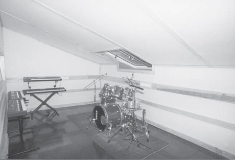
Figure 5.23 The very neutral studio room at Noites Longas studio, in Redondos, Portugal (1993)
5.11 Dialogue Recording Rooms
When the first edition of this book was published, the general theme was about music recording studios, with some sallies into the world of cinema. However, numerous requests were received from readers about providing more information on rooms for dialogue recording. In sub-Section 5.8.7, mention was made of a ‘problem’ which was 70dB down on the signal. In practice, it was considered not to be a problem, because the musical performances themselves would mask any such low level sound. On the other hand, in dialogue recording the rapid decays of consonants can leave very exposed any artefacts which a room may introduce. Nevertheless, a totally dead room is out of the question because actors, as opposed to singers, tend to work to a picture, and do not use headphones.
In typical voice-over situations, an actor will watch a picture on a screen, be it a flat panel or a projected image (or possibly still a cathode ray tube), and listen to the original dialogue via a loudspeaker. When the time comes to record, the loudspeaker is muted and the actor performs to the image, synchronising the voice to the lip movements on the screen. The performance by the actor is in every way a performance, and if the room is too absorbent it will cause the voice to be forced and the sound to be unnatural. Conversely, if the room is too live, it will impart its own characteristics on the recorded sound, and these may not correspond well to the environment depicted in the image. For example, if three people were talking on a sand dune, in a desert, the scene would lose credibility if the voices sounded like they had been recorded in a room. Room sounds can always be added artificially, but it can be very difficult to remove them once recorded.
In dialogue rooms, it can often be useful to provide highly absorptive surfaces behind the actors, at least down to the lower limits of the vocal frequency range, around 90Hz or so. Reflective surfaces (the screens themselves often help, here) can be placed forward of the actors, and cardioid microphones can be pointed towards them (the actors). Such a directional microphone would not respond to the vocal reflexions, which would be absorbed by the ‘trap’ towards which the microphone was pointing, yet these reflexions would give sufficient life to the room so that the actors could feel comfortable and natural during their performances. The big difference to remember, here, is that for actors, the room is their performance stage, whereas for singers, the foldback signal in the headphones is their environmental ‘reality’. Much more will be said abut this in Chapter 24.
In too many cases, not enough space is allocated to rooms which are ‘only’ for dialogue recording, and the existence of so many small rooms has led to a general tendency to believe that they are all that is necessary. The reality is somewhat different, because to provide a highly controlled acoustic with a directional microphone sufficiently far from an actor’s mouth, in order to avoid proximity effect problems, requires a room of decent size, say 4m×4m or so, before acoustic treatment, and at least 3m in height.
Figure 5.24 shows a room which was built by a supposedly professional acoustic design and construction company, but what used to suffice for talk studios for AM radio will often now not meet the requirements for modern, home theatre presentations. In the room shown, the floor was carpeted and the walls and ceiling were covered in panels of pressed cotton-waste felt, geometrically formed into rounded wedges. The panels were mounted on 5cm wooden battens, screwed to the concrete walls, and with 4cm of mineral wool of about 40kg/m3 density in the gap. The room sounded dark, and surprisingly dead, but there was always something unnatural at the lower end of the vocal register, and the recording personnel were constantly filtering out these frequencies, which not surprisingly also tended to thin out the voices of the actors because the equalisation was acting on the direct signal as well as on the room sounds.
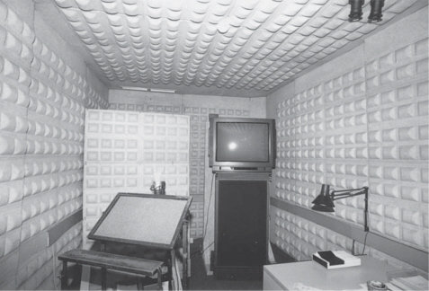
Figure 5.24 A voice recording room constructed without the required space behind the ‘absorbent’ panels on the walls and ceiling
Figure 5.25 shows the published performance plots for the wall panels, and it is quite clear that with the distance ‘d’ equalling almost zero, as was the case in the aforementioned room, the absorption begins to fall off rapidly below around 800Hz. However, with a spacing of 300mm between the support frame and the concrete walls, adequate absorption could be achieved at 100Hz (a coefficient of around 0.4), but many studio owners want to see the space that they are paying for, and many contractors are happy to declare that the customer is always right, despite the laws of acoustics demanding something different from both of them.
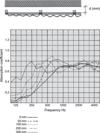
Figure 5.25 Absorption coefficient versus frequency for the compressed cotton-waste panels with respect to their distance from a solid wall
One obvious solution to the problem in the room under discussion would have been to mount the panels ‘properly’ on new frames set 300mm (1ft) from the concrete walls, but it was generally considered that the remaining area within the room would have been too small for the actors and equipment, so a different solution was sought. (Once again, a room of insufficient size had been built.)
Figure 5.26 shows a sister room after reconstruction. In order to only occupy the same space as the original treatment, a totally different approach was devised. To the concrete walls and to the suspended plasterboard ceiling were attached 6cm panels of an 80kg/m3, open cell, reconstituted polyurethane foam, marketed under the name of Arkobel. The foam was attached by contact/impact adhesive, although cement-and-latex adhesives could have been used, which although slow in drying do not give off noxious vapours. To the foam was then attached, by similar adhesive, 3.5cm panels of a porous nature, made from wood shavings and Portland cement, with ample air spaces in-between. This material is quite heavy, being around 18kg/m2 for 3.5cm thickness, so the whole system acts in a combination of ways, as a multilayer absorber, with absorption being due to the tortuosity of the pores, membrane characteristics and panel absorber characteristics. This type of material was originally manufactured in the United Kingdom as Woodcemair, being made from wood shavings, cement, and being lightly compressed so that air voids still remained. Materials such as Celenit (from Italy), Heraklith (from Austria) and Viruter (from Spain) are similar options based on the same theme, with different characteristics of absorption and aesthetics.
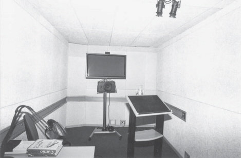
Figure 5.26 A room similar to the one shown in Figure 5.24 but after treatment with a more appropriate combination of materials, yet still only occupying the same space as the original panels
The panels shown in Figure 5.24 were purely porous absorbers, which could only act on the velocity component of the acoustic wave. They only become effective absorbers when spaced about a quarter of a wavelength from a solid surface. The wavelength of 800Hz is 340 (the speed of sound in m/s) divided by 800, or about 42cm. One quarter of this wavelength would be around 10.5cm (4 inches) which corresponds well with the average distance of the protrusions in the pressed cotton panels from the concrete walls, but below this frequency the absorption dropped off rapidly. However, the system shown in Figure 5.26 maintained this porous absorption above 800Hz, but introduced the highly damped, pressure component dependent absorption of multi-layered membrane and panel absorbers at lower frequencies. The decay time with frequency of the room is shown in Figure 5.27 (a), with the corresponding decay time of the original room shown in Figure 5.27 (b).
Unlike in music recording rooms, what happens in dialogue rooms below the range of the vocal frequencies is of little relevance, because even if resonances exist there is nothing in the voices to excite them. Even consonant sounds have difficulty in exciting low frequency resonances. The only real low frequency problems occur if the loudspeaker reproduction becomes less defined during the rehearsal phases before the takes, and even then only if there are low frequency sounds on the original soundtrack.
In these types of dialogue recording rooms the recording technician/ engineer is sometimes working in a corner of the same room, monitoring on headphones and using a small mixing console. Obviously, in such cases, any noisy equipment must be outside the room. Some people feel that this arrangement can give a close, more immediate communication between actors and technicians. Alternatively, some rooms have small ‘control cubicles’ adjacent to them, but some of these are really far too small to allow any form of accurate monitoring via loudspeakers. A somewhat ludicrous control cubicle is shown in Figure 5.28, ludicrous at least if serious attempts at monitoring via loudspeakers are to be made. In fact, if the only realistic means of monitoring in such a small room is via headphones, then the technician/engineer may as well be in the same room as the actors, remote controlling the machinery, and monitoring via headphones. The room shown in Figure 5.28 is simply too small for the introduction of any worthwhile acoustic treatment, and so a coloured, boxy sound is virtually inevitable. Playback of a take via a good loudspeaker in the well-controlled room in which the actors perform would be a much more realistic way of judging the quality of the recording, so there is good justification for working that way if no decent-sized and acoustically treated control room is available.
Figure 5.28 An absurdly small ‘control booth’. Rooms of such small sizes are effectively too small to allow a flat monitoring acoustic, and colouration is unavoidable
In general, the greatest error in the design of most rooms for dialogue recording, be they recording rooms or control ‘cubicles’, is that they are usually too small to allow good acoustic characteristics to be enjoyed, and the control of their deficiencies by equalisation is almost certain to degrade the natural qualities of the actors’ voices. Better recordings are usually made in adequate sized rooms, with space available for the appropriate acoustic treatment down to at least 100Hz.
5.12 Summary
Neutral rooms are good, general-purpose recording spaces. They lightly enrich the character of musical instruments without imposing their own presence on the sounds.
Some life in a room is usually necessary to make the musicians feel comfortable. Uncomfortable musicians rarely play at their best.
Neutrality is easier to achieve in larger spaces than in small ones.
To achieve neutrality, parallel reflective surfaces should be avoided, strong resonances should be suppressed, and sufficient specular reflexions should be present to give a sense of spaciousness.
The neutrality of a recording room should not only be judged directly by the ear, but also via microphones.
Floors should normally be of wood, but should neither creak nor rattle. Certain room proportions are known to give rise to a more even spread of modes. In some circumstances these can give useful starting dimensions.
Plasterboard-based acoustic control shells can usefully control the very low frequencies, and deadsheet membranes can be used to control the mid-bass frequencies. Fibrous layers can be used to control cavity resonances and frequencies from 2 kHz upwards. The upper bass/low mid frequency region is best controlled by a combination of geometry, membranes and fibrous materials.
The proximity of the ceiling to the floor, and to the microphones and instruments, can be rendered benign by combinations of diffusion, reflexion and absorption.
To neutralise an existing room, or a sound isolation shell, it may be best to suppress the reflexions as much as possible then to re-build the desired life into the rooms.
Neutral rooms are very flexible in use, but they may not be able to match the character of more idiosyncratic rooms in some circumstances, even with the aid of artificial (electronic) processing. (See Chapter 6.)
What is acoustically parallel at low frequencies may be far from geometrically parallel.
Neutral rooms of 500 to 1000 m3 would tend to have decay times of around 0.3 to 0.6 s in the mid frequencies, but reflexions should also be present.
Large surfaces of diffusers tend to lead to decay times which are too long for many neutral rooms. Rooms with too much diffusion can lack the necessary specular reflexions which give rise to a sense of spaciousness.
Fabrics used for wall coverings should be non-resonant when stretched and mounted.
Small neutral rooms are difficult to achieve, because the reflexions are rapid and dense, and late reflexions are unobtainable. For general neutrality, small rooms may have to be rather dead, with a few surfaces reflective at high frequencies to achieve a little ‘air’.
Perversely, it is the very same digital recording equipment that exposes low level room sounds in the recordings which also, due to its mechanical noise and bad positioning, frequently masks these room sounds in the control room monitoring. This leaves them exposed to many domestic listeners, whilst going unnoticed by the recording personnel.
It is difficult to find any simple surface treatments to make a small room neutral-to-dead. Complex structures of low depth may have to cover almost the entire surface area, other than the floor, to be able to adequately control the room resonances.
Post-processing of the recording will not usually be able to remove the sound of a bad room.
Multiple-layer treatments can be used to trap the sound energy within the layers. Very small rooms can have very flat low frequency responses because they are operating within their pressure zones, where no modes exist. The pressure zone is in the region below the frequency of the lowest room mode.
Very small rooms can be controlled at low frequencies by a ‘limp bag’ concept and resilient walls.
Sound vibrations have difficulties passing from a lighter medium to a heavy, dense one.
Small, strange resonances in highly damped rooms are often only audible because there are no other room sounds to mask them. What may sound strange in a room may be inaudible via microphones in normal use.
Rooms for dialogue recording may differ in their needs from rooms for recording musical performances.
Highly damped rooms can be beneficial when dry voices must be artificially processed to match a picture.
Rooms used for dialogue recording are often too small to allow adequate acoustic control down to the 100Hz region, and so suffer from colouration.
Room problems below about 80Hz are usually of no consequence because voices contain no frequencies sufficiently low to excite such low resonances.
______________________
* Many of the descriptions in this chapter refer to the use of cotton-waste felt. This is not because it is necessarily sonically superior to mineral wool, glass-fibre wool, or other fibrous materials, but it is because it has been found by many people to be much less offensive to work with. The cotton felt is not an irritant, but face-masks should still be used when working with it in large quantities or confined spaces, because the ingestion of the fibres is still unwise.
1 Louden, M. M., ‘Dimension Ratios of Rectangular Rooms with Good Distribution of Eigentones’, Acoustica, Vol. 24, pp. 101–4 (1971)
2 Gilford, C. L. S., ‘The Acoustic Design of Talks Studios and Listening Rooms’, Journal of the Audio Engineering Society, Vol. 27, No. 1/2, pp. 17–29 (Jan/Feb 1979)
3 Bonello, O. J., ‘A New Criterion for the Distribution of Normal Room Modes’, Journal of the Audio Engineering Society, Vol. 29, No. 9, pp. 597–605 (September 1981)
4 D’Antonio, Peter, ‘Two Decades of Diffusor Design and Development’, AES Pre-print, 99th Convention, New York (1995). (See also Bibliography below.)
5 Schroeder, M. R., ‘Diffusive Sound Reflection by Maximum Length Sequences’, Journal of the Acoustical Society of America, Vol. 57, No. 1, pp. 149–50, January (1975)
6 Schroeder, M. R., ‘Comparative Study of European Concert Halls: Correlation of Subjective Performance with Geometric and Acoustic Parameters’, Journal of the Acoustical Society of America, Vol. 56, No. 4, pp. 1195–201 (October 1974)
7 Schroeder, M. R., ‘Progress in Architectural Acoustics and Artificial Reverberation in Concert Hall Acoustics and Number Theory’, Journal of the Audio Engineering Society, Vol. 32, pp. 194–203 (1984)
8 Schroeder, M. R. and Gerlack, R., Response to ‘Comments on Diffuse Sound Reflection by Maximum Length Sequences’, Journal of the Acoustical Society of America, Vol. 60, No. 4, p. 954 (October 1976)
9 Walker, R., The Design and Application of Modular, Acoustic Diffusing Elements, Proceedings of the Institute of Acoustics, Vol. 12, Part 8, pp. 209–18 (1990)
10 Tyndall, J., DCL, LCD, FRS, On Sound, 6th Edn, Longmans Green and Co., London (1895)
Bibliography
D’Antonio, P. and Cox, T., ‘Two Decades of Sound Diffusor Design and Development, Part 1: Application and Design’, Journal of the Audio Engineering Society, Vol. 46, No. 11, pp. 955–76 (November 1998)
D’Antonio, P. and Cox, T., ‘Two Decades of Sound Diffusor Design and Development, Part 2: Prediction, Measurement and Characterization’, Journal of the Audio Engineering Society, Vol. 46, No. 12, pp. 1075–91 (December 1998)
Cox, T.J. and D’Antonio, P., ‘Acoustic Absorbers and Diffusers’, Spon Press, Abingdon, UK and New York, USA (2004)