
The Behaviour of Multiple Loudspeakers in Rooms
Loudspeakers in different environments. Steady-state and transient response differences. Pan-pot laws. Fold-down compromises. Discrete and phantom image differences. Multiple surround formats. Sub-woofer options.
Chapter 11 discussed many aspects of the performance of loudspeakers in rooms. Principally, it was dealing with single loudspeakers, but a very important aspect of the performance of sound control rooms for music recording in the spacial performance in stereo or surround. This aspect of the performance of loudspeakers is difficult to specify, and in the case of a single loudspeaker, which is usually what loudspeaker specifications relate to, it is currently (2007) impossible to specify. Nevertheless, without knowing the basic behaviour of multiple loudspeakers it will be difficult to appreciate some of the more philosophical discussions that follow in later chapters. Let us now look at the behaviour of multiple loudspeakers in some detail. First, however, we must begin by once again considering mono sources.
14.1 Mono Sources
Figure 14.1 shows a familiar set of response plots for a typical loudspeaker in an anechoic chamber. The individual plots show the response on-axis, and at various angles and directions off-axis. When moving horizontally across the front of such a mono source, it should be evident from the plots that the high frequencies will progressively reduce as one travels further off-axis. If one were to move behind the loudspeaker, then one would not expect to hear much top at all, and a glance back at Figure 11.5 will clearly show why.
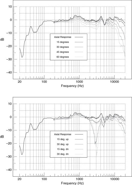
Figure 14.1 Horizontal and vertical directivity plots of a Tannoy ‘Reveal’ loudspeaker
If the high and low frequencies are equal in level on-axis, then it should be obvious that in the room as a whole, there will be more low frequency energy, because at no point do the high frequency levels exceed the low frequency levels. Conversely, the lows are present in many places at much higher levels than the highs. In fact, the areas of the high and low frequency patterns in Figure 11.5 give a reasonable idea of the relative proportions of the radiated power in each frequency band. Nevertheless, in an anechoic chamber, in an arc of ±15° across the frontal axis, a highly uniform response can be achieved.
If we now transfer the same loudspeaker from Figure 14.1 into a reverberation chamber, the diffuse field that the chamber gives rise to will serve to integrate all the responses from all the directions. As Figure 11.5 shows, the low frequencies are radiating in all directions, so they should also be radiating more total power into the room. Figure 14.2 bears this out, and shows the significantly higher level of low frequencies that would be perceived in the far field at any point in a highly reverberant room. In fact, even on-axis at quite short distances, the response would still largely be as shown in Figure 14.2 because the critical distance in such a room, where the direct field is equal in energy to the reverberant field, is very short indeed. (See also Section 11.2.) Figures 14.1 and 14.2 were from actual measurements made by Dr Keith Holland in the anechoic and reverberation chambers, respectively, at the Institute of Sound and Vibration Research (ISVR) in Southampton, UK. All music listening rooms fall somewhere between these extremes, therefore the loudspeaker responses in those rooms will also fall between the same extremes.
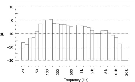
Figure 14.2 Tannoy Reveal, total power response
14.2 Stereo Sources
Let us now consider two ideal point monopole sources, representing a stereo pair of perfectly flat, omni-directional loudspeakers. When reproducing a central mono image, the combined directivity would be as shown in Figure 14.3(a). For a single, mono source, the radiation pattern would simply be spherical and equal at all frequencies (as shown in Figure 14.3(b)), and thus the frequency response at any point in the room would be flat. Unfortunately, as shown in Figure 14.4, the off-axis frequency response of a phantom central image from a stereo source is anything but flat.1 Considering the directivity plot shown in Figure 14.3 it could hardly be expected to be flat. Figure 14.5 goes one stage worse – a central, in-room image created by four sources in a surround system.2 It can be seen that the situation can rapidly get out of hand. Only on-axis in an anechoic chamber can a phantom central stereo image mimic a discrete central image from a centrally positioned loudspeaker, and even then only as measured by a microphone, not by ear. In a reflective room, this can never be achieved, because all the off-axis radiation will be of the comb-filtered nature shown in Figure 14.4. All reflexions from points other than on the central plane between the loudspeakers will therefore also exhibit comb-filtered responses. It must be self-evident that if a single source radiates a flat response in all directions (we are still speaking about perfect omni-directional loudspeakers, here) and a stereo pair radiates comb-filtered responses at all points off the central plane, then the reflexions will return what they receive (given perfect reflectors, of course). This means that the reflective field will exhibit a different frequency balance from a central mono source, such as a single central loudspeaker, than from a phantom central image from a stereo pair.
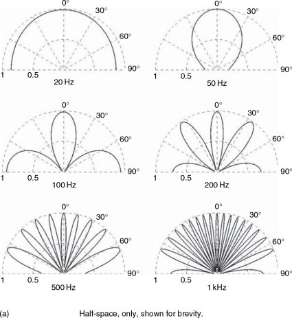
Figure 14.3 (a, b) Discrete versus phantom source patterns. (a) Polar response of a pair of ‘perfect’ loudspeakers when producing a central phantom image and spaced 3 metres apart
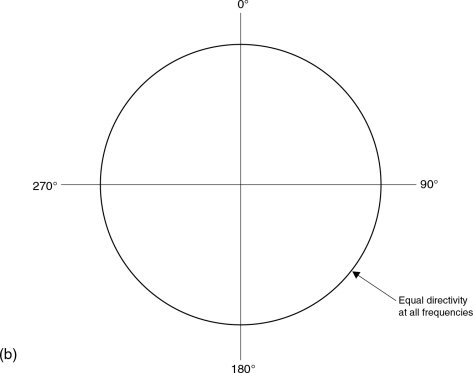
Figure 14.3 cont. (b) Polar response of a perfect loudspeaker in an anechoic chamber. The above plot represents the polar response of a perfect, discrete, mono source
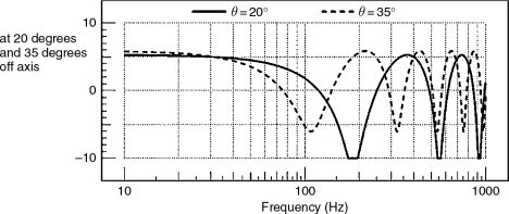
Figure 14.4 Effect of comb filtering. Off-axis frequency response of a pair of ‘perfect’ loudspeakers when producing a central phantom image in an anechoic chamber
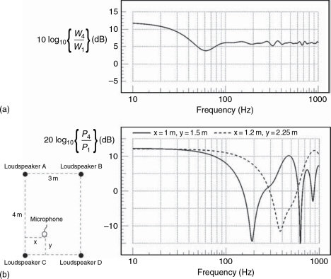
Figure 14.5 Frequency response of four ‘perfect’ loudspeakers radiating the same signal. (a) Total power response in a highly reverberant room. (b) Combined frequency response of four omni-directional loudspeakers at two different position in an anechoic chamber
In rooms with significant modal activity, it must also be remembered that the modal pattern is very much dependent on the point(s) from which the room is driven. A central mono source has one drive point, whereas a phantom central image has two points of origin, separated by the distance between the loudspeakers, and neither point corresponds with the position of the phantom image. The two means of generating a central image can drive the room very differently, and thus cannot be expected to sound the same at any point in the room. Only on, or close to, the central plane in anechoic spaces will the discrete and stereo sources produce identical results, but as has already been mentioned, even these two cases may not be perceived to sound identical, the reason for which will be discussed in the following paragraphs.
14.3 Steady-State Performance
On ‘steady-state’ signals, the situation can be very different between anechoic and reverberant rooms. In anechoic conditions, the interference pattern from the left and right loudspeakers would sum by 6 dB on the central plane, and for a distance either side of it which would be dependent upon wavelength. The 3 dB of ‘extra power’ superimposed upon the 3 dB radiated power increase is gained at the expense of lower SPLs elsewhere in the room. Away from the central plane, the interference patterns would produce comb filtering, as shown in Figure 14.4, the nature of which would be position dependent. Off-axis there would also be additional low frequency power, which was the result of the additional radiation due to the mutual coupling. (See Glossary for Mutual coupling, if necessary.) That this is not perceived on-axis as solely an LF boost, but as an overall boost, can be considered to be a result of an overall directivity change when the two spaced drivers are operating together.
In highly reverberant conditions, a totally diffuse sound field would build up. As we are still considering perfectly flat omni-directional loudspeakers, here, a similar frequency distribution would be radiated in all directions, and so the response at any point in the room would be the same. It would be a simple power summation of the two sources, producing a 3 dB increase in level plus whatever low frequency boost that resulted from mutual coupling. Musically, though, things would sound very confused, with one note blurring into the next. In practice, many listening rooms of a reflective nature tend towards the 3 dB central summation, and some repercussions of this fact will be discussed in Section 14.5, but we should take a minute to look more closely at the area of 6 dB summation in the more anechoic conditions, because the width of the region is very frequency dependent. The region of perfect summation would only be around half a wavelength in width. At 20 kHz, this would be around one centimetre, but at low frequencies it would be many metres. At around 2 kHz, for a two-eared human being sat on the centre line, there would be an effective cancellation due to the spacing of the ears. This is due to the fact that the path length distances are not the same from each loudspeaker to each ear, as shown in Figure 14.6, which is another mechanism by which a centrally panned image, from a pair of loudspeakers, differs in the way that it arrives at the ears compared with the arrival of the sound from a discrete, central loudspeaker.
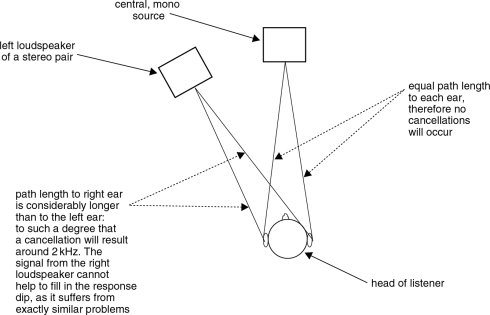
Figure 14.6 Path-length anomalies for phantom central image
14.4 Transient Considerations
On the central plane of a stereo pair of loudspeakers, the transient pressures will also sum, producing a single pulse of sound 6 dB higher than that emitted by each loudspeaker individually. At all other places in the room, as the different distances to the two loudspeakers create arrival time differences, double pulses will result. This effect is clearly shown in Figure 14.7. Although it may seem to an observer on the central plane that four times the power (+6 dB) of a single loudspeaker is being radiated at all frequencies, to an observer off the central plane this would only be the case at low frequencies. At higher frequencies, the effect of the constructive and destructive superposition of the signals results in an average increase of 3 dB. The zones of coupling are shown diagrammatically in Figure 14.8. However, this still apparently leaves us with a ‘magic’ extra 3 dB of power on the centre line, which for transients cannot be described in terms of radiation impedance, because radiation impedance is a frequency domain concept, and transients exist in the time domain. We need to look at this behaviour in a different way.
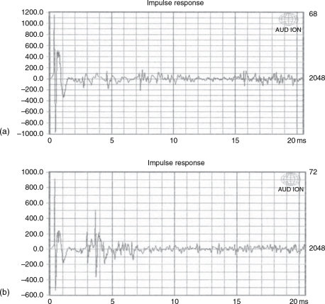
Figure 14.7 (a) Impulse response received from a centrally panned image from a pair of loudspeakers. Measurement taken on the common axis of both loudspeakers (centre line). The response from a central, mono loudspeaker would be essentially similar. (b) Impulse response, as (a) but as received from a position 1 m behind (a) and 1 m to the left of the common axis (centre line). There are two clear impulses with the one arriving from the right-hand loudspeaker, about 3 ms later in time, and about 5 dB lower in level
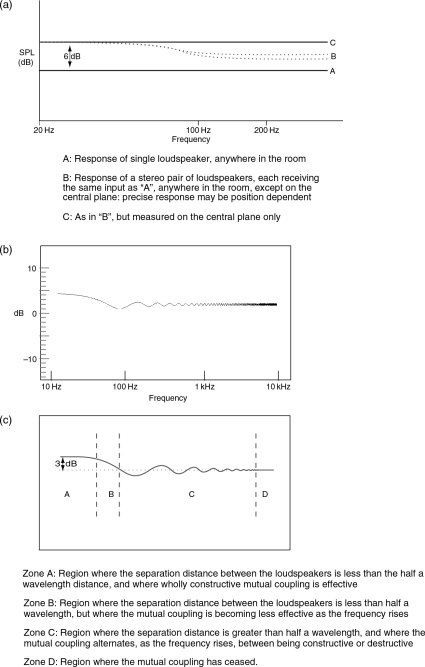
Figure 14.8 Mutual coupling effects – omni-directional sources. (a) Pressure amplitude response in an anechoic room. (b) Frequency response of a pair of loudspeakers at any position in a reverberant room – combined power output. (c) Zones of loading/coupling – general response as in (b)
In the case of a perfect delta function (a unidirectional impulse of infinitesimal duration), the points of superposition would only lie on a two-dimensional, central plane, of infinitesimal thickness. As this would occupy no perceivable space, then no spacial averaging of the power response would be relevant. With a transient musical signal, which has finite length, there would be positive-going and negative-going portions of its waveform. At the places along the central plane where the transients crossed, they would not only meet at a point, but would ‘smear’ as they interfered with each other over a central area, either side of the central plane. Around this central plane, the pressures would superpose, producing a pressure increase of 6 dB over a finite region each side of the centre line. (Doubling the pressure increases it by 6 dB.) As they crossed further, they would produce regions of cancellation, which would show overall power losses equal to the power gain in the central region of summation. The total power would thus remain constant when area-averaged. The above effect is shown in Figure 14.9, in which the average height of all the transients occurring at any one time in the room would be the same as that of a single transient emitted by one loudspeaker, though they would be doubled in number as there are two sources. Only where they interfered with one another would there be disturbances in their height, but there would be no extra total power in the room, just the simple sum of the power radiated by the two individual loudspeakers.
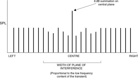
Figure 14.9 Pulse superposition
On transient signals therefore, because of their existence as separate bursts of energy, the performance of anechoic and reflective conditions differs only in that the reflective rooms will add an ever-increasing number of reflected energy burst to the environment, though of ever decreasing energy, which will add to the overall, perceived loudness. However, bearing in mind that a reflective/reverberant room must, by definition, be anechoic until the first reflexion arrives, then dependent on the room size and the length of the transient burst, the subjective perception of the transient could change over time from the anechoic to the reverberant state. Continuous types of sounds (e.g. bass guitar notes) would be perceived more consistently in accordance with the type of room in which they were being reproduced. Perhaps it is little wonder then, that stereo perception can be so variable from room to room.
The perception of a 3 dB overall central summation (as tends to exist in most reverberant spaces) was at the root of the old pan-pot dilemma: should the electrical central position of a pan-pot produce signals which are 3 dB or 6 dB down relative to the fully left or fully right positions? Mono electrical compatibility of the stereo balance requires constant voltage, therefore each side should be 6 dB down (half voltage) in the centre, in order to sum back to the original voltage when added electrically. (The pan-pots, or more fully panoramic potentiometers are potential (voltage) dividers, so, it is the voltages, which must sum.) In the case of an acoustic stereo central image in a reasonably reverberant room, it is the power from the two loudspeakers which must sum to unity in the centre, which therefore requires a condition whereby the output from each loudspeaker would be only 3dB down (half power) when producing a central image. Nevertheless, Figure 14.8(b) shows how below the mutual coupling frequency, the low frequency response would still approximate to the −6 dB requirement, because the power summation would tend to be augmented by a further 3 dB due to the mutual coupling effect between the two loudspeakers.
In stereo radio drama, where voices are often panned across the sound stage, −3 dB pan-pots would produce a uniform level as a voice was panned from left, through centre, to right. However, if the programme were then to be broadcast in mono, the voice would be perceived to rise by 3 dB as it passed through the centre position in the stereo mix, due to the electrical mixing of the signals. If the same task were to be repeated for a bass guitar, then in the mono broadcast it would still be subject to the same, uniform, 3 dB rises as it passed through the centre of the stereo mix. Somewhat inconveniently, though, when heard in stereo, it would be perceived to increase only in its low frequency content as it passed through the centre position on its way from left to right, due to the mutual coupling between the two woofers. The degree of boost, and its frequency of onset, would be dependent on the distance between the left and right loudspeakers, introducing yet another variable. It is therefore different for every different set of monitoring conditions, and cannot be compensated for in any standard mixing console.
As there is usually little dynamic panning of low frequency instruments in stereo music recording, a −3dB centre position used to be considered optimum. In the case of radio drama, where mono compatibility for the majority of the broadcast listeners is a great priority, a −6dB centre position was customarily required. Many mixing console manufacturers will produce consoles with different pan-pot laws for different applications, though they usually opt for a −4.5 dB compromise, which produces only a 1.5 dB worst case error in either instance. This compromise fits nicely with most real-life rooms in which music will be heard, because they tend to exist in a region somewhere between reverberant and anechoic. In fact, in truly anechoic conditions, the acoustical sum on the central plane is identical to the electrical sum, at least in the region where the axial response holds true; but this is a central-planeonly condition. Elsewhere in the room, the summation approximates to the panning effect at all points in a more reverberant space, though with less confusion in the sound. The repercussions of these anechoic/reverberant and steady-state/transient phenomena create many problems for designers of subjectively reliable means of producing electrical fold-down systems for stereo/multichannel compatibility, and for compatibility between large and small cinema mixing theatres. (See Section 21.12.1).
14.6 Limitations, Exceptions and Multi-Channel Considerations
The theoretical concept of the perfect omni-directional loudspeaker therefore breaks down badly when the question arises of where to put them. Within any room other than one that is either perfectly anechoic or perfectly reverberant, boundary reflexions from the rooms in which they were situated would produce an irregular frequency response. Perfectly reverberant conditions would be useless for listening to music, as the perception of much detail would be swamped by the reverberation. Anechoic conditions, in which fine detail is most readily perceived, allow no reflected energy, so the only sound heard by a listener is that which passes directly from the loudspeaker to the listener. In such conditions there is no perceivable difference at the optimal listening position between a perfectly omni-directional loudspeaker and one that radiates a uniform frequency balance on an axis pointing directly towards the listener. A uniform response for plus or minus twenty or thirty degrees off-axis allows for some movement about the central listening position, and this is quite easy to achieve in practice. Therefore, in anechoic conditions, omni-directional loudspeakers would do nothing except waste power by radiating sound in unnecessary directions.
Just as the perceived response of a central image generated by two monopole loudspeakers will be different from that generated by a single, centre loudspeaker, as was shown in Figures 14.4 and 14.6, an image that is generated by four loudspeakers is likely to differ from an image generated by two. There could be a further mutual coupling rise of up to 3 dB as the number of sources was again doubled as shown in Figure 14.5. With dipole loudspeakers though, this build-up may be different, because they are pressure-gradient sources, coupling to pressure nodes, and not velocity nodes (pressure anti-nodes). Any bass lift due to mutual coupling will be greater in the case of typical multi-channel dynamic loudspeakers, as compared to electrostatics. This situation can pose even more problems for people trying to design electronic systems to ‘fold-down’ multi-channel mixes into stereo or mono, while still attempting to maintain the original musical balance.
As well as all the fold-down compromises caused by the effects of the rooms and combined loudspeaker directivity, it can now also be seen that the desired fold-down can also depend on the type of loudspeakers on which the music was mixed, as well as those on which it would be reproduced. To make matters worse, the compatibility of mixes is also affected by the fact that the optimum fold-down must take into account the frequency dependence of the directionality of human hearing. The subjectivity desirable level of the sounds formerly in a rear loudspeaker may be considered excessively loud, or bright, when reproduced from a frontal direction after fold-down. This is because they may have been made brighter in the surround mix because the ears are much less sensitive to higher frequencies arriving from behind the head. Thus when assessing claims about the degrees of compatibility of mixes from surround to stereo or mono, one must ask . . . ‘Compatibility with what?’ The electrical fold-down equation may differ very greatly from the purely acoustic, or the electro-acoustic, or the perceived psychoacoustic fold-down requirements. The acoustic nature of the listening environment will also add its own variables – the room coupling. Once again, relatively anechoic (i.e. highly damped) monitoring conditions would seem to offer the fewest complications for the electrical fold-down requirements. What is more, as the spaciousness would be in the surround, there would be little need for a room to add any more if faithful reproduction was required.
So, even if it was possible to design perfect loudspeakers, the question would remain as to exactly in what sort of a room they would behave perfectly in stereo pairs? Only on the central plane in anechoic conditions, it would appear. In all other cases, the room will impart its influence upon the perceived response, and, even in anechoic conditions, there are aspects of the weaknesses inherent in stereophonic reproduction which mean that we cannot precisely reconstruct the sound from a single source by means of a phantom image generated by two sources. The situation is that we have imperfect loudspeakers and imperfect rooms, trying to reproduce a fragile concept.
This produces a strong argument in favour of three or five frontal loudspeakers, not only in terms of image stability when moving off-axis, but also from the point of view that fewer phantom sources and more discrete sources means that reflexion, absorption and diffusion will all be more uniform in frequency content. True, in real situations, the reflexion, absorption, and diffusion will not all be uniform in their frequency response, but nonetheless, less confusing interaction from multiple sources for single image positions means, at the very least, a more predictable set of starting conditions. Unfortunately, this still presumes omni-directional, point source loudspeakers with perfectly uniform frequency responses, which do not exist.
The job of acousticians and electro-acousticians to get the best out of any given set of circumstances is no easy task. Only by a very careful balancing of all the parameters can optimum end results be realistically hoped for, but parameters can only be balanced if they are understood, and many of the points being made in this chapter are not widely appreciated. The reason why no one principle of listening room design is universally accepted is because of the truly vast number of variables involved, of which the problems that have been discussed here form only a very small part. All of this does little, however, to change the perceptions in the minds of the public at large about room acoustics being a black art. In fact, in many instances, the object of an acoustician’s work is to keep the variables within defined, acceptable limits, rather than to seek an as yet unachievable perfection.
14.7 Surround in Practice
The drawings in Figures 14.10 to 14.23 show 14 surround formats, all except one of which are either already in use or have been proposed by people or organisations of sufficient respect to render them free of any ‘crank’ or ‘minority interest’ status. The exception, the 8.1, is a derivation from the combination of the needs to be able to work in either Dolby Ex (6.1) or Sony SDDS (7.1) (see Figure 14.16) where the provision of both capabilities in one room has left a situation where the summation of the two requirements would seem to be begging to be used.
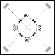
Figure 14.10 4ch ‘Quadrophonic’, also used in basic Ambisonics
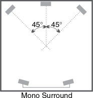
Figure 14.11 Dolby Stereo 3/1 (Pro-Logic)
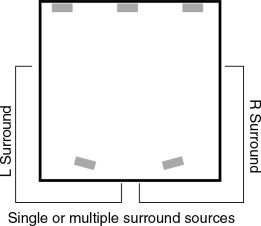
Figure 14.12 5-channel 3/2
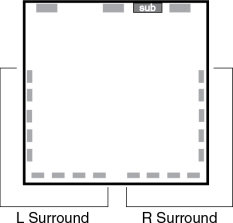
Figure 14.13 Dolby Digital surround
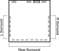
Figure 14.14 Dolby EX 6.1
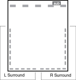
Figure 14.15 Sony 7.1 (SDDS) [Sony Dynamic Digital Sound]
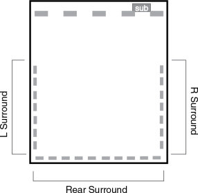
Figure 14.16 8.1? (7.1 SDDS with separate rear channel.)
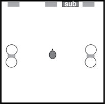
Figure 14.17 5-channel surround using dipole side/rear loudspeakers
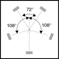
Figure 14.18 Holman Pentagon. ‘Pentagon’ (Boston Audio Society Speaker, Vol. 22, No. 2, p. 31, May 1999) [by Alvin Foster]
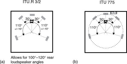
Figure 14.19 (a) ITU.R 3/2. (b) ITU 775
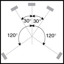
Figure 14.20 HDTV study group – Japan, Preprint 4253, Copenhagen, 1996 AES. The surround loudspeakers are more distant than in the ITU specifications shown in Figure 14.19
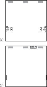
Figure 14.21 Two variations on a similar theme – diffuse surround from two discrete sources. (a) Surround speakers mounted in room, pointing at diffusers on walls – as used by Bell and Dobson. (b) As at TOBIS, with diffuse surround sources – NXT panels – DMLs. See References 3 and 4 of Chapter 21
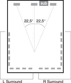
Figure 14.22 THX requirement for film dubbing theatres – 45° subtended angle
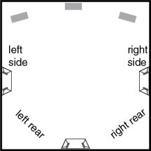
Figure 14.23 Bipolar surround sources. Proposed by Fosgate,3 using processors to decode 7 channels processed from 5
It must be understood that surround is not just a little more complicated than stereo, nor even twice as complicated – it is vastly more complicated. There is a saying ‘Give a person enough rope and they will probably end up by hanging themselves’. Well, surround supplies an awful lot of rope, and the potential for people to get hung up in its complexities is enormous. Stereo supports one phantom sound stage between the two loudspeakers. Five-channel surround (let alone seven or more), by allowing panning between any individual pair or groups of loudspeakers, provides 26! Except in the centre of the loudspeaker arrangement in free-field acoustics, such as in an anechoic chamber, (and even ignoring human hearing directional differences) surround systems will tend to result in different responses of timbre for any instrument panned across any of the possible different sound stages.
In fact, at very low frequencies, mutual coupling effects between the sound sources may result in different low frequency responses even in anechoic conditions, depending on the number of loudspeakers supporting any one phantom image. When the systems are transferred into a room, and boundary reflexions begin to affect the responses, the concept of any sound mixing personnel being able to predict the result outside of the actual mixing room becomes a lottery. Despite all the magazine articles by producers and engineers who are excited about the creative possibilities of surround, the subject is a minefield, ready to trap anybody who does not know exactly where the mines are laid. Many people think that they do know about surround, but as James Moir reputedly pointed out many decades ago, ‘If one thing is certain about acoustics, it is that if anything seems obvious it is probably wrong’.
The 14 layouts shown in Figures 14.10 to 14.23 indicate how difficult it has been to agree on any simple standard set of compromises. Many of the systems are specifically engineered to solve given problems, or sets of problems, but in doing so they each tend to create other problems. The fact that the minds of so many specialists have been put to work on the problems, only to result in chaos, suggests that not only is there no easy solution to the problems of surround, but that the simple, attractive, flexible, high quality systems that the marketing people have been searching for probably does not and will not exist. It is that complicated. It therefore becomes very difficult to specify an environment for the optimum mixing of music in surround because the goals are still not clearly defined.
Even the drawings in Figures 14.10 to 14.23 are simplified inasmuch as many offer the options of whether to use full-range loudspeakers, or to use satellites and a sub-woofer, or even satellites and dual sub-woofers. With these options, our 14 systems would now become 40 or more, each with its own specific tonal differences. Their respective strengths and weaknesses would be dependent upon room conditions, programme material, and how the mixing personnel chose to distribute the sounds.
Much orchestral and organ music definitely benefits from the low frequency ‘wash’ that can envelope the listeners when listening to a pair of stereo full-range loudspeakers. When such music is transferred to a loudspeaker system with satellite loudspeakers and a mono sub-woofer, the effect is largely lost. However, in rooms in which the low frequency response is less than very well controlled, the single source provided by a lone sub-woofer can often lead to a less confused low frequency response than would be experienced when using two full-range sources.
The question of ‘to use, or not to use’ sub-woofers is complex. Undoubtedly, they can offer the flexibility of being able to position them in a room such that the low frequency coupling can be optimised, but such positioning, whilst benefiting the flatness of the low frequency pressure response, may not be optimal in terms of time alignment. This is of particular importance in the context of surround sound when a front positioned sub-woofer may be both physically and temporally misaligned with the rear loudspeaker. The commonly held belief that there is no directional information in frequencies below 300Hz is erroneous. The mis-location of sub-woofers can demonstrate this, easily. When sub-woofers are placed in non-optimally damped rooms, it is advisable to mount them off-centre in order that they will drive the rooms asymmetrically. The central positioning, by virtue of the equal distance to each side wall, tends to cause symmetrical driving of the standing-wave field, which can concentrate reflected energy into narrow frequency bands. By contrast, the asymmetrical drive of the standing-wave field by a non-centrally positioned sub-woofer tends to create more peaks and dips in the response, but of lower magnitude, yielding a generally flatter overall response.
With such off-centre positioning of the sub-woofer, it is usually prudent to offset it to the right, because for orchestral music, the cellos and basses are normally positioned towards the right. For pop, rock or electronic music, where the bass guitar and bass drum are normally centrally panned, then whether the sub-woofer is offset to the left or to the right is of little consequence. However, when listening to orchestral music with the sub-woofer offset to the left, the non-collocation of the low frequencies with their respective instruments can often be noticeable.
Similarly, in surround systems, when a sub-woofer is positioned at the front of a room, with a full-range keyboard instrument panned to the rear, walking backwards and forwards in the room can often reveal very clearly the non-collocation of the different frequency bands. The coincidence of the arrival time of the full frequency range can have a great bearing not only on the punch and impact of a sound, but also on the room-to-room compatibility of the mixes. Mixes done in rooms with badly positioned sub-woofers can make it very difficult to judge the optimum tonal balance of the low frequencies, and it can be difficult in such rooms to make a mix that travels well to other rooms. The optimum balance of bass drum and bass guitar can be quite difficult to achieve in rooms with temporally offset sub-woofers. Furthermore, many sub-woofers use band pass enclosures that have notoriously poor time responses, and this tends to add to the time-smearing confusion. (See Appendix 2.)
The situation with multiple full-range loudspeakers is complex. In a five-channel system, the low frequency response of a signal panned to any individual source is reasonably predictable. However, when a low frequency signal is routed to two or more loudspeakers, the frequency response will be dependent upon to how many loudspeakers it is routed, and the distance between the loudspeakers. The number of loudspeakers will determine the degree of low frequency boost due to the mutual coupling of the sources, and the distance between the loudspeakers will determine the frequency below which the mutual coupling boost will begin to take effect. Clearly, if total freedom of choice exists in whether to use single or multiple low frequency sources, then the degree of predictability of the response compatibility of the mixes with other systems will be poor.
It is more or less standard in serious stereo control rooms to refer mixes to a pair of full-range loudspeakers, two-and-a-half to four metres apart. At the time of writing, there is still no consensus about how to manage the low frequencies for surround music mixing. In the cinema world, the situation is well defined, with the more or less general use of a discrete low frequency effects channel. There is usually also little multi-source panning, except when the full power of the entire system is needed for effect, such as during an explosion. Most music is panned between no more than two frontal loudspeakers, which are usually capable of extending down to 40 Hz or so. In the TV and video world, a single sub-woofer tends to be the norm, though it must be said that when the sound is intended to accompany pictures in a domestic situation, it is rarely, if ever, given the sort of attention that it would receive in music recording.
Ironically, it is in the world of music recording, which is supposedly the flagship of the sound recording industries, that no consensus exists about how to deal with the low frequencies in multi-channel recordings. The lack of standards organisations, the great power of the vested interests of equipment manufacturers marketing their products, and the widespread ignorance of the difference between many of the low frequency options have all had their effect in delaying any general decision on how to handle the low frequencies of surround mixes. Nevertheless, perhaps the principal reason why chaos has ruled for so long is the fact that there is no simple option that will suit all types of music. Mono had one source. Stereo, from the outset, used the pair of low frequency sources. However, surround has a multitude of low frequency options, such as:
- five discrete sources all available as desired
- three full range channels at the front with reduced low frequency capacity in the rear channel
- left front and right front carrying the main panned music mix, with the centre channel principally for vocals or dialogue
- low frequencies handled by one sub-woofer
- low frequencies handled by stereo sub-woofers
- low frequencies handled by multiple, processed sub-woofers.
The problem is that all of the above options will sound different in any one room, and the way that each one will translate to a different system in a different room will also be different. From the point of view of producing control room and monitor systems with any semblance at all to a reference standard, first we need a standard. Without such a standard, the concept of surround sound cannot really be considered high fidelity.
14.8 A General View
The room effects become significantly more problematical as the number of simultaneously radiating sound sources increases. In fact, the problems can multiply so rapidly that with four, five or six sources, as are commonly advocated for surround systems, the complexity can become so great that there may be no solutions allowing delivery of the same degree of fidelity as can be achieved in better stereo rooms. If surround mixing is not carried out with full respect to the acoustic limitations, then trading quality for quantity may become a fact of life. The directional reflexion philosophies used in many stereo control room concepts will not function when 360° of sound sources are used. Many of the surround-sound problems can be solved by highly damped rooms in which all the ambience is in the surround, but this could lead to very unpleasant room acoustics in which to be when the music is switched off.
The subject of surround control rooms will be discussed at much greater length in Chapter 21, but this brief look at the situation will have at least prepared the way for the battles to come.
14.9 Summary
A central phantom image, produced by two spacially separated loudspeakers, creates a very different reflexion pattern in a room when compared to a central mono source. The two sources of the central image produce comb-filtered reflexions.
A central phantom image is also subject to a perceived dip around 2 kHz, due to the different distances from each loudspeaker to the two ears. A central mono source does not exhibit the same effect, so the timbre will sound different to a phantom image.
Pan-pot laws ideally need to be tailored to the acoustics of the rooms in which the music will be heard.
The theoretical concept of the perfectly flat omni-directional loudspeaker would appear to be of no advantage in practical circumstances.
Automatic electrical fold-down of surround mixes to fewer channels is fraught with compromises.
Five-channel surround is vastly more complicated than stereo, and can exhibit at least 26 different phantom sound stages between different loudspeaker pairs or groups. Stereo has one phantom sound stage.
At low frequencies, the mutual coupling between sources will be dependent upon the number of sources in use and the distance between them. The former will dictate the amount of boost, and the latter the frequency below which the boost will occur.
There are more than a dozen authoritatively proposed surround configurations. When one considered sub-woofer options, the number is close to 40.
Single sub-woofers should be slightly offset to the right of the centre-line.
Sub-woofers can produce considerable time smearing of the low frequency response, due to both the physical displacements and the common use of band-pass cabinets with inherently poor time responses.
The problem of surround compatibility from mixing room to listening room is considerable.
References
1 Holland, Keith R. and Newell, Philip R., ‘Loudspeakers, Mutual Coupling, and Phantom Images in Rooms’, presented at the 103rd Audio Engineering Society Convention, New York, Preprint, No. 4581 (1997)
2 Holland, Keith R. and Newell, Philip R., ‘Mutual Coupling in Multi-Channel Loudspeaker Systems’, Proceedings of the Institute of Acoustics, Vol. 19, Part 6, pp. 155–62 (1997)
3 Fosgate, James., designer of the Dolby Pro Logic II System
Bibliography
Borwick, John, Loudspeaker and Headphones Handbook, 3rd Edn, Focal Press, Oxford, UK and Boston, USA (2001). [In particular, Chapter 1.]
Newell, Philip, and Holland, Keith; Loudspeakers – for music recording and reproduction, Focal Press, Oxford, UK (2007)