
Below is a brief description of some of the technical terms found throughout this text. Experience has shown that although some of the terms may be familiar to many readers, they have often been misunderstood or misused. This glossary attempts to clarify the definitions of the terms, at least as used in British English.
Acausal filter
A filter applied, usually digitally, which has advanced knowledge of the signal arriving via delaying the main signal on which it is intended to act – effect before cause through prior knowledge of the cause. See Causal filter.
Active systems
Filters or loudspeaker systems, for example, where an external power source needs to be applied as well as the drive signal. A filter based on semiconductors or valves, driven from an external battery or mains supply, and placed ahead of a power amplifier in a loudspeaker system is an example of an active filter. See Passive systems.
Anechoic chamber
A room that is designed to simulate free-field acoustic conditions by means of the placement of highly absorbent materials on all surfaces. The absorbent materials usually are in the form of wedges pointing into the room. This arrangement ensures that sound waves arriving at the room edges are maximally absorbed for all angles of incidence. The lower frequency limit of anechoic performance is set by the length of the wedges, which are effective down to a frequency where the wedge length is equal to one-quarter wavelength. However, what little reflexions still exist will return more weakly from the distant walls of the larger anechoic chambers than from the nearer walls of a smaller chamber using similar wedges.
Variously known as anechoic rooms or free-field rooms.
See also Semi-anechoic chamber and Hemi-anechoic chamber.
Analogue to Digital converter. A device using a highly stable internal clock which samples the audio voltage waveform at a rate higher than at least twice the highest frequency of interest, and puts out a digital binary signal that represents the voltage level of each sample. For example, to sample a maximum frequency of 8 kHz, the sampling rate would need to be in excess of 16,000 samples per second. See also D to A.
Audio frequency range
The range of frequencies over which the human ear is sensitive is usually considered to be from 20 Hz to 20 kHz. A number of commonly used frequency ranges are listed below. The span of frequencies quoted for each range should not be treated as exact; they are included as an approximate guide only.
Name |
Frequency range |
Infrasonic |
0–20 Hz |
Very low |
15–50Hz |
Low |
20–250Hz |
Lower mid |
200–1000 Hz |
Mid |
250 Hz–5 kHz |
Upper mid |
2–6 kHz |
High |
5–20 kHz |
Very high |
15–25 kHz |
Ultrasonic |
20 kHz–1013 Hz |
Back e.m.f.’s
The electromotive forces (voltages) which are generated in a loudspeaker system by the mechano-magnetic interactions. They superimpose on the drive signal (forward e.m.f.) but are usually largely damped by the energy sinking (absorbing) action of the low output impedance of an amplifier, which thus provides a high damping factor. Excessive impedance in loudspeaker cables, for example, can reduce this damping effect, and hence in such systems the back e.m.f.’s would play a greater part in the overall response of the system.
Bookshelf loudspeaker
A genre of domestic orientated loudspeakers whose low frequency responses are aligned to try to achieve a flat far-field response when the loading provided by a wall is taken into account, as would typically be the case when a loudspeaker was mounted on a bookshelf.
Causal filter
A filter in which the effect takes place after the cause. See Acausal filter.
Cellular
Composed of cells, which can be either open or closed. In closed cell foams, for example, each cell acts like a small balloon. When compressed or distorted the air trapped inside cannot escape, and so the cell acts as a good spring but a poor sound absorber. Open cell foams are generally poorer springs but better acoustic absorbers. (For equal densities.)
Close field
The region close to a sound source, such as a loudspeaker, in which the sound field is largely that due to the source, and is little affected by the room reflexions, resonances, or reverberation. See also Near field.
Codec (code-decode)
An algorithm for allowing data compression in digital systems, usually in accordance with psychoacoustic phenomena, which allows maximum data compression with minimum acceptable (perceptually/subjectively dependent) audible degradation of the reconstructed sound.
Damping
Damping refers to any mechanism that causes an oscillating system to lose energy. Damping of acoustic waves can result from the frictional losses associated with the propagation of sound through porous materials, the radiation of sound power, or causing a structure with internal losses to vibrate.
D to A
Digital to Analogue converters receive digitally coded signals, representing voltage waveforms, and by means of clocking and filtering, produce an analogue output voltage that should be as close a representation as possible of the waveform represented by the digits. See also A to D.
dBA
A weighted (filtered) measurement scale where the filter curves are roughly the inverse of the 40phon contour of equal loudness. The scale was principally developed to relate to the subjective annoyance of noise around the 30–50dB SPL ear sensitivity at mid frequencies, by correcting the high and low frequency measured levels to the same subjective level as the mid frequencies. (See Figure 2.4.)
dBC
Similar to dBA but based on the inverse of the 80 phon contour of equal loudness, relating more to the subjective frequency balance at typical music listening levels. The low frequency response of the dBC curve is almost flat.
Deadsheets
Limp membranes having considerable inertia but little stiffness. They are widely used for the mechanical damping of acoustic waves. Those used in studio construction are normally between 3 and 15 kg/m2.
Decibel
The standard unit of measure for level, or level difference. One tenth part of a bel. Multiplying a given quantity by 1.26 (to two significant figures) will give an increase in level of one decibel.
For example: 1 W× 1.26 = 1.26 W (+1dB relative to 1 W); 1.26W × 1.26 = 1.59 W (+2 dB relative to 1 W); 1.59 W× 1.26 = 2.00W (+3dB relative to 1 W). It must be borne in mind that in all cases, a decibel represents a power ratio.
Decibels and sound pressure level (SPL)
Many observable physical phenomena cover a truly enormous dynamic range, and sound is no exception. The changes in pressure in the air due to the quietest of audible sounds are of the order of 20 μPa (20 micro-pascals), that is 0.00002 Pa, whereas those that are due to sounds on the threshold of ear-pain are of the order of 20 Pa, a ratio of one to one million. When the very loudest sounds, such as those generated by jet engines and rockets, are considered, this ratio becomes nearer to one to one thousand million! Clearly, the usual, linear number system is inefficient for an everyday description of such a wide dynamic range, so the concept of the bel was introduced to compress wide dynamic ranges into manageable numbers. The bel is simply the logarithm of the ratio of two powers; the decibel is one tenth of a bel.
Acoustic pressure is measured in pascals (newtons per square metre), which do not have the units of power. In order to express acoustic pressure in decibels it is therefore necessary to square the pressure and divide it by a squared reference pressure. For convenience, the squaring of the two pressures is usually taken outside the logarithm (a useful property of logarithms); the formula for converting from acoustic pressure to decibels can then be written:
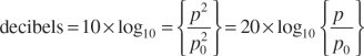
where p is the acoustic pressure of interest and p0 is the reference pressure. When 20 μPa is used as the reference pressure, sound pressure expressed in decibels is referred to as sound pressure level (SPL). A sound pressure of 3 Pa is therefore equivalent to a sound pressure level of 103.5 dB, thus:
![]()
The acoustic dynamic range above can be expressed in decibels as sound pressure levels of 0 dB for the quietest sounds, through 120dB for the threshold of pain, to 180 dB for the loudest (severely ear-damaging) sounds.
Decibels are also used to express electrical quantities, such as voltages and currents, in which case the reference quantity will depend upon the application (and should always be stated).
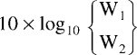
When dealing with quantities that already have the units of power, such as sound power or electrical power, the squaring inside the logarithm is unnecessary and the ratio of two powers, W1 and W2 expressed in decibels is then
Distributed mode loudspeaker (DML)
A type of loudspeaker where the motor system excites a plate of high modal density. The source is diffuse and acts like neither a piston nor a point source. Radiation takes place from both sides of the panel, but the response is not typically that of a more conventional dipole, even when the panel is unbaffled. The stereo imaging is not as good as with conventional loudspeakers, but the response tends to be less disturbed by the room acoustics. Such loudspeakers can be advantageous as the ambient rear channels of a surround loudspeaker system for example.
Doppler distortion
Frequency modulation dependent on the speed with which a source of sound is either approaching or receding from a listening position. The most common example is perhaps that of a train whistle, or horn, which suddenly drops in pitch as the listening position is passed. The whistle exhibits a constant frequency of output, but when it is approaching the listening position, the period between the cycles is compressed as the arrival delay shortens with time. As the source approaches, effectively the wavelength is shortened. This gives rise to the impression that a higher frequency is being emitted. The time of arrival for each subsequent cycle is reduced as the train approaches because it is emitted from a point nearer to the listener than was the previous cycle. Once the listening point is passed, the opposite effect occurs, with each subsequent cycle emanating from a more distant position, lengthening the wavelength and hence suffering a greater arrival delay. The frequency is thus perceived to have lowered. The degree of pitch change is dependent upon the relative speed of the sound source and the listener. (C. J. Doppler, 1842.)
Eigenfrequency
Frequency of the Eigentones (see below).
Eigentones
The natural resonant tones of a space (or any other resonant system, in fact), ‘eigen’ being German for ‘own’. A room’s own tones. If a room is driven (excited) by a noise signal containing all frequencies, then all the eigentones will be driven. When the drive signal is terminated, however, only the eigentones will continue to ring-on, the decay rate being a function of size and total absorption. If a room is driven by a musical signal, only the eigentones that correspond to frequencies in the musical signal will be driven, and then only those eigentones will ring on when the music stops.
The eigentones thus dictate which frequencies will ring-on when the drive signal is stopped, but the input signal determines which eigentones are driven. Eigentone is another term for resonant mode. (See Mode.) If a room is driven at a frequency that does not correspond with an eigentone (mode), then the room response will decay more rapidly, once the drive signal has been stopped, than the frequencies which correspond with the eigentones. This is why widely spaced room modes give rise to uneven overall responses in a room. Frequencies corresponding to eigentones (modes) will be reinforced or cancelled, depending on source and receiver position, but other frequencies will be unaffected. See Standing waves and resonances.)
The European currency unit, roughly equivalent to 1.35 US dollars in 2007. During the reading of the first draught of this book for assessment by the publishers, a referee requested that the currencies used in the text should be converted to one standard unit, such as the euro or the U.S. dollar. In reality, this proved difficult to achieve in any meaningful manner because the wild fluctuations of the currencies would lead to distorted senses of values outside of the local territory of each currency. In mid 2001, the euro would buy 87 cents of a U.S. dollar. By mid 2004 it would buy 1 dollar 34 cents, a rise in value of over 50 percent. Consequently, reference in this book to things manufactured in the USA is given in dollors, and to things made in Europe, in euros. Where any other currencies are stated, some means of assessing the relative value at the time referred to will be given in the text.
Far-field
The far-field is the region in which the radiation from a loudspeaker, or other acoustic source, can be considered equivalent to that of a point source, and in which the sound pressure and velocity reduce by 6 dB for each doubling of distance from the source.
Feedback
- The instability that occurs when the output from a microphone is reproduced by a loudspeaker system, the output of which arrives back at the microphone. Regenerative feedback develops when the overall gain is greater than 1. Also known as ‘howlround’.
- The instability that occurs when an output of an electrical amplification system is re-applied to its input.
- A term used by orchestral musicians to describe the way in which they hear the output from their own instruments reinforced via reflexions in their performance space. When fed to them via loudspeakers or headphones, the usual term is foldback.
- Negative feedback (phase reversed) is used in electronic amplifier circuitry to reduce distortion.
Fourier Transform
The mathematical transform linking the time domain representation of a signal to its frequency domain representation. Application of the Fourier Transform to a signal (waveform) reveals the frequency components in terms of their magnitude and relative phase (the Spectrum). Application of the inverse Fourier Transform to the spectrum yields the original waveform.
Frequency
The rate of change of phase with time. The number of complete cycles per unit interval of time for a sinusoidally time-varying quantity. The repetition rate of any cyclic event. Unit: Hertz: (Hz); previously measured in units of cycles per second (c.p.s.), and even earlier in half-vibrations per second.
The response of a system in terms of its amplitude and phase response. See (Pressure) amplitude response and Phase response.
Group delay
The frequency dependent response delays through electrical or mechanical systems which are given rise to by phase distortions. The group delay is related to the degree of phase shift.
Haas effect
H. Haas, 1951. See Precedence effect.
Hemi-anechoic chamber
An anechoic chamber with one hard boundary (usually the floor) in which the sound sources can be embedded. Equates to 2π space (a hemisphere).
Hysteresis
The lagging of effect when an applied force varies in amount, and where the movement in one direction is not re-traced when the force giving rise to that movement is reversed.
Impedance
A combination of resistance and reactance. Symbol Z. The ratio of pressure to velocity in acoustic systems, or voltage to current in electrical systems, expressed at a given frequency. (See also Resistance and Reactance.)
Infrasonic
Relating to frequencies below approximately 20 Hz. See Subsonic.
Intensity ‘Sound intensity’ is a very specific term, and represents the flow of acoustic energy. It is measured in units of watts per square metre, and should not be confused with either sound power level (SWL), sound pressure level (SPL) or loudness, but it is associated with the sound intensity level (SIL).
Interference field
See Standing wave field.
Kinetic energy
Energy of motion. Energy possessed by a body due to its motion, which can be converted to other forms of energy through the application of a braking force.
Linearity
A system can be said to be linear when the output contains only the frequencies applied to the input. A falling amplitude response is therefore a linear distortion. Such a response is NOT non-linear, as may be erroneously stated in many advertisements. See Non-linearity.
Loss factor
The reciprocal of the Q-factor. See Q-factor.
The property of some materials, for example iron, of expanding and contracting due to the influence of an applied magnetic field.
Microphone directivity patterns
Most microphones consist of a small diaphragm that moves in response to changes in the pressure exerted on it by a sound wave; the diaphragm motion is then detected and converted into an electrical signal.
The simplest form of microphone is one that has only one side of the diaphragm exposed to the sound field. If the diaphragm is sufficiently small, such a microphone will respond equally to sounds from all directions, and is termed ‘omni-directional’.
A microphone which has both sides of the diaphragm open to the sound field will only detect the difference between the pressures on the two sides. When a sound wave is incident from a direction normal to the diaphragm, there will be a short delay between the pressure on the incident side and that on the far side, and the microphone responds to the resultant pressure difference. When a sound wave is incident from a direction in line with the diaphragm, the same pressure is exerted on both sides of the diaphragm and the sound is not detected. This arrangement results in a ‘figure-of-eight’ or dipole directivity pattern.
If an omnidirectional microphone element and a figure-of-eight microphone element are mounted close together and their outputs summed, the resultant directivity pattern will lie between the two extremes of omni-directional and figure-of-eight patterns. If the sensitivities of the two elements are the same, the combined directivity pattern is known as cardioid, because of its heart shape. Various other patterns, such as hyper-cardioid and super-cardioid are achieved by varying the relative sensitivities of the omni-directional and figure-of-eight elements. Similar directivity patterns can be realised using only one microphone element. The microphone diaphragm is mounted at one end of a short tube, and the delay introduced to one side of the diaphragm by the tube gives rise to an approximation to a cardioid directivity pattern. More complex directivity patterns can be achieved by using more than two elements; the SoundField microphone, for example, has four elements that can be combined in a variety of ways.
Minimum phase and non-minimum phase
A minimum phase signal/system is one in which the phase shift associated with the amplitude response is the minimum that can be allowed whilst still exhibiting the properties of a causal system (one in which the output never arrives before the input). As there is a strict relationship between amplitude and phase in such systems, correcting either one will inevitably tend to correct the other. The low frequency response boost given rise to by the flush mounting of a loundspeaker in a wall is an example of a minimum phase response change, which therefore can be equalised to restore the free-field response in terms of both amplitude and phase (and hence it will also restore the time [transient] response). The essential factor is that no appreciable delay is involved between the generation of the signal and the effect of whatever is influencing it. If there is no appreciable delay, then there can be no appreciable phase-shifts, hence minimum-phase, or more fully, minimum phase-shift.
‘Non-minimum phase’ responses are those where amplitude correction, alone, cannot correct any phase disturbances. The far-field response of a loudspeaker in a reflective room is an example of a non-minimum phase effect. Here, there is a delay between the signal generation by the loudspeaker and the superimposition of the boundary reflexions on the overall response. Reflexion arrival times create phase irregularities, which are frequency and distance (time) dependent, so no simple manipulation of the amplitude response of the source can adequately compensate for the complex disturbances.
Another example of a non-minimum phase effect is in the combination of the various outputs of crossovers. In any filter circuits, either mechanical or electrical, there are inherent Group delays for any signal passing through them. The amount of group delay increases as the filter frequency lowers, and as its order (6, 12, 18, 24, etc. dB/octave) increases. A crossover will thus have different group delays associated with each section, and when the outputs are recombined, they will not produce an exact replica of the input signal. For this reason, conventional equalisation cannot be used to correct for response errors at crossover points. Amplitude correction will lead to further phase distortion, and hence time response errors. In practice, most crossovers above first-order are non-minimum phase devices.
Mode
A special pattern of vibration whose position remains invariant, as when a travelling wave and its reflexions superimpose themselves between two or more boundaries such that the peaks and troughs in the waveform coincide, and appear static. See Standing wave field.
Modes and resonances
Sound consists of tiny local changes in air density that propagate through the air as a wave motion at the speed of sound. The speed of sound is around 340 metres per second at normal room temperature and, although it is temperature dependent, it is independent of variations in the ambient pressure, and is the same at all frequencies. The frequency of a sound wave is measured in cycles per second (c/s or cps) known more usually these days as Hertz (Hz), and is usually represented by the symbol f. The distance that a sound wave travels in one cycle at any frequency is known as the wavelength, represented by the symbol λ, and has the units of metres. The speed of sound is represented by the symbol c. The relationship between wavelength, frequency and the speed of sound is simple; wavelength is equal to the speed of sound divided by the frequency, or λ = c/f. Therefore, for example, a sound wave at a frequency of 34 Hz has a wavelength of 340/34 = 10 m.
As a sound wave propagates away from a source in a room, it will expand until it reaches a reflective room boundary, such as a wall, from which it will reflect back into the room. The reflected wave will continue to propagate until it reaches other boundaries from which it will also reflect. If there is nothing in either the room or the boundaries to absorb energy from the wave, the propagation and reflexion will continue indefinitely, but in practice some absorption is always present and the wave will decay with increasing time. The point on the cycle of a sound wave (the phase of the wave) when it reaches the boundary depends upon the distance to the boundary and the frequency of the wave. Figure 4.7 shows how waves at different frequencies, propagating from the same source, arrive at a boundary with different phases.
A rigid boundary will change the direction of propagation of an incident sound wave, but will maintain its phase, so the phase of a reflected wave can be calculated from the total distance propagated from the source. If this total distance is equal to a whole number of wavelengths, then the wave will have the same phase as it started with. When two boundaries are parallel to each other, a sound wave will reflect from one boundary towards the other, and then reflect back again to where it started, continuing back and forth until its energy is dissipated. If the distance between the boundaries is such that the ‘round trip’ from the source to the first boundary, on to the second boundary, and back to the source is a whole number of wavelengths, then the returning wave will have the same phase as the outgoing wave, and will serve to reinforce it. This situation is known as resonance. Resonances can also occur due to reflexions from multiple boundaries; the necessary requirement being that the sound wave eventually returns to a point with the same phase as when it left. One can imagine a whole set of possible combinations of reflexions in a typical room that allows the wave to return to its starting point, and therefore a whole set of frequencies for which resonance will occur. In fact, in theory, every room has an infinite number of possible resonances.
As stated above, if there is nothing in the room or the boundaries to absorb energy from a sound wave, a short duration sound pulse (or transient), emitted from a source, will propagate around the room indefinitely. Of the infinite number of possible paths that the wave can take, only those that correspond to resonances at frequencies contained in the pulse will be continually reinforced; all other paths will not be reinforced. After a short time, the resulting sound field can be thought of as simply a sum of all of the resonances that have been excited. These resonant paths are known as the natural modes of the room, and the resonant frequencies are known as the natural frequencies, or ‘eigentones’, of the room; both are determined uniquely by the room geometry. ‘Eigen’ is German for ‘own’, so the eigentones are a room’s own particular, natural, resonance frequencies.
When sound absorption occurs within the room or boundaries, resonant modes still exist, but the wave will decay at a rate determined by the amount of absorption. To maintain a given sound level in a room in the presence of absorption, the source needs to be operated continuously, at a level dependent upon both whether or not resonant modes are being excited and the amount of absorption present. When the sound source emits a transient signal in the presence of absorption (for example, switching off a continuous signal), many different paths – not just resonant modes – will be excited, but after a short time, only the resonant modes will remain (because they tend to have less absorption); the room will ‘ring’ at the resonance frequencies until the modes decay. The reverberation time of a room is a measure of the average rate of decay of the sound in the room when an otherwise continuous sound source is switched off; it is the time taken for the sound level to fall to 60 dB below its initial, continuously excited, level. As the amount of absorption is increased, the sound level at the resonant frequencies will reduce, but the bandwidth of each mode (the range of frequencies over which the mode can be excited to a significant degree) will increase. When the boundaries are fully absorbent, the room modes no longer exist (an anechoic chamber).
When sounds such as speech or music are heard in a room, the level of the continuous components of the sound will be determined by whether or not they coincide with any room resonances that are excited. The transient components will ‘hang on’ at the resonance frequencies after the transient has gone. It should also be understood that the perception of the modal activity is not uniform within the space, because of the spacial distribution of the nodes and antinodes.
Mutual coupling
Mutual coupling is the term used to describe the interaction between two or more sound sources radiating the same signal. If the diaphragms are receiving different, uncorrelated inputs, then the output power summation will be simply that of the output of the different diaphragms. However, if the diaphragms are receiving the same input, then for frequencies whose wavelengths are greater than eight times the distance between the diaphragms (i.e. the diaphragms are less than one-eighth of a wavelength apart) the outputs will be substantially in-phase at any point in the room. The radiated pressures (not powers) will then superimpose, giving rise to a 6 dB increase in SPL for each doubling of the radiating area if the diaphragms are radiating the same power. This implies four times the output power, yet when the radiated powers are equal, but the radiated signals are uncorrelated (i.e. totally different signals) only a 3dB SPL increase (due to the simple power summation) would result. Where a close boundary reflects a wave back on to the radiating surface of a diaphragm, the effect is the same as if a second diaphragm were radiating the same signal – the mirrored room analogy – and so the diaphragm radiates twice the power that it would do if moved away from the boundary.
This seemingly 1 + 1 = 4 situation is due to the fact that, for a given diaphragm velocity, the power output is proportional to the diaphragm radius raised to the fourth power. Doubling the diaphragm area therefore yields a fourfold increase in power. The increased low frequency radiating efficiency of large diaphragms can be thought of as being due to all the individual parts of the diaphragm mutually coupling. The pressure radiated by one part of the diaphragm resists the movement of the adjacent parts. The increase in radiation resistance on a mass-controlled diaphragm, typical of a heavy woofer (whose movement can be considered independent of the local air pressure), gives rise to increased work being done, by having a greater pressure of air to push against, so more power is radiated.
As the frequency of radiation rises, or the loudspeakers (or the loudspeaker and a reflective surface) are sited further apart (i.e. the diaphragms are separated by more than one-eighth of a wavelength), the coupling becomes less in-phase so the radiation boost reduces. As the frequency or separation distance continues to rise, regions of in and out of phase interference will result, giving rise to a combined output power response as shown in Figure 14.8.Only for a listener on the central plane between the loudspeakers will the 6 dB pressure summation be maintained. (See also Figure 14.9.)
In a reverberant room, the output from a pair of stereo loudspeakers reproducing a central mono signal will sum by 6 dB on axis, at all frequencies, but the reverberant field will be driven by the combined power response, as shown in Figure 14.8(b). The overall sound, therefore, will be darker (with more low frequencies) than that from a central mono source radiating the same signal and receiving the same input power as the mutually coupling pair.
Much more on this subject can be found in Reference [1]. at the end of the Glossary.
Near field
There are two quite distinct and separate definitions of the near field of a source of sound; one is related to the geometry of the source whilst the other has to do with the rate of expansion of radiating waves. The region beyond both near fields is known as the far field.
The geometric near field is defined as that region close to a source where the sound pressure does not vary as the inverse of the distance from a source. The extent of the geometric near field is dependent upon the detailed geometry of the sound source and is finite only at frequencies where the wavelength is shorter than a typical source dimension (for a circular piston this is when the wavelength is equal to the piston diameter); there is no geometric near field at lower frequencies. A point source does not have a geometric near field at any frequency.
The acoustic near field (or hydrodynamic near field) is defined as that region close to a source where the air motion (velocity field) does not vary as the inverse of the distance from a source, although the acoustic pressure may. The extent of the acoustic near field is inversely proportional to frequency: it is large at low frequencies and small at high frequencies. The sound field radiated by a point source has a sound pressure that varies as the inverse of distance from the source at all frequencies and distances. The air motion only varies as the inverse of distance in the far field. For practical sources, the extent of the acoustic near field is affected also by source geometry.
Decisions relating to the proximity of a listener to a close-field monitor should be made by considering the geometric near field only; the ear, being essentially a pressure sensitive organ, is insensitive to the presence of the acoustic near field.
Newton
A standard unit of force; symbol N. Easy to remember examples are that one newton is roughly equal to a weight (on the earth’s surface) of 100 g, and that an apple of medium size is attracted to the earth by a force of around one newton. A force of one newton bearing down on a spring would be applied by a 100 g weight on the surface of the earth.
Non-linearity
A system is said to be non-linear when the output contains frequencies which were not present in the input signal, and are not due to system noise. Harmonic distortion, intermodulation distortion and rattles are sources of non-linearities. A system exhibiting any of these is said to be non-linear. See Linearity.
Noise weighting curves (dBA, etc.)
The human ear does not have a flat frequency response; a low frequency noise will generally sound quieter than a higher frequency noise having the same sound pressure level. A measurement of sound pressure level therefore does not yield an accurate measurement of perceived loudness unless the frequency content of the noise is taken into account. Noise weighting curves are used to convert sound pressure level measurements into approximations of perceived loudness, by discriminating against low and high frequency noises. The most commonly used noise-weighting curve is known as A-weighting. An A-weighting curve is simply a filter with a response that rises with increasing frequency up to 2 kHz, above which it falls off gently.
The frequency response of the human ear changes with changes in sound pressure level (see Figure 2.1), so different weighting curves are required for different levels. The dBA curve was developed for signals having loudness below 40 phon, the dBB curve was intended for use around 60 phons. At levels over about 80 phon, the dBC curve should be used. Other curves are also in use, such as dBD, which can be used for high level industrial noise, and dBG, which is used for infrasonic and very low frequency noise assessments. The responses of some of the weighting curves are shown in Figure 2.4.
The widespread use of the dBA curve for the assessment of noise can give rise to poor results in situations when another weighting curve is more appropriate. For example, Figure 2.4 shows the dBA curve superimposed on the inverse of the equal loudness contours – similar to those in Figure 2.1, but upside down. Only at about 1 kHz and 6 kHz do all the curves agree. Between 3 and 4 kHz, errors of up to 10 dB can be seen, and at low frequencies, the A-weighting curve can over-assess or under-assess noise nuisance levels by up to 20 dB, depending upon level. The dBA curve is often used at relatively high levels; a purpose that it was never intended for, and is not suited to, but sometimes this needs to be done for comparison purposes.
In any case, noise weighting should only be applied when one requires an approximation to the perceived loudness of a sound; it is therefore of most use in noise assessment. Noise weighting should never be applied when absolute values of sound pressure are required; in the measurement of loudspeaker frequency response, for example. Here, a flat measurement (unweighted) should be used unless clear specifications demand otherwise.
Objective and subjective assessment
In acoustics in general, and in audio in particular, there is often some disagreement between that which our measurements tell us and that which we hear. In audio, objective assessment involves measuring the performance of a piece of equipment using instruments, and comparing this performance with a desired specification. Subjective assessment, however, involves auditioning the equipment under carefully controlled conditions and assessing particular aspects of the sounds that are heard. The successful assessment of the quality or suitability of a piece of audio equipment therefore, ideally, needs both approaches. Objective assessment is more easily carried out in the laboratory, or during production runs, than subjective assessment. To make a reliable and repeatable subjective assessment usually requires the ears of a number of subjects, and hence, often, a large amount of time.
Particulate
Relating to particles. Particulate motion = motion of the particles.
Pascal
A pressure of one newton per square metre. See Newton.
Passive systems
Systems, such as filters, without any source of external power other than the signal energy itself. An inductor/capacitor filter immediately before a loudspeaker drive unit is an example of a passive filter. See Active systems.
Phase response
The relative phase of the input and output signals as a function of frequency.
Phon
A unit of perceived loudness, such that a given change in the phon level would always produce an equal, subjective loudness change, irrespective of the actual SPL change. The contours in Figure 2.1 represent phon levels, which it can be seen do not relate directly to the physical sound pressure levels.
Pink noise
Filtered white noise (reducing 3 dB/octave with frequency) which yields equal energy per octave.
Pinna
Plural: pinnae. The outer part of the ear that projects outside the head. The ear flap.
Plasticine
The trade name of synthetic clay used for modelling. It is highly plasticised and does not set hard.
Potential energy
The energy of position; such as imparted on a body by raising it in a gravity field. The energy concentrated in a spring is also potential energy.
Precedence effect
Also referred to as the Haas effect, and the law of the first wavefront. When two short-duration sounds are heard in rapid succession, the tendency is for the second sound to be psychoacoustically suppressed. The pair of sounds is perceived as one sound, coming from the direction of the first arriving source. The precedence effect operates when the second sound arrives within approximately 0.7–30 ms after the first sound.
The affect can often be overridden if the second sound is 7–15 dB higher in level than the first sound.
(Pressure) amplitude response
The ratio of the output amplitude of a system divided by the amplitude of the input as a function of frequency. When sound pressure is involved, the term ‘pressure’ is prefixed: for electrical or mechanical systems, the term ‘amplitude response’ suffices.
Psychoacoustics
Unlike the related discipline of acoustics, which is concerned with the physics of sound, psychoacoustics is the science of the perception of sound, particularly by humans. The stereo illusion, the cocktail party effect and the perception of pitch are all examples of psycho-acoustic phenomena.
PVA
Poly-vinyl acetate. A water-based adhesive that is water resistant once dry.
Q-factor
A measure of the sharpness of the peak in a resonant system. It is defined as

where
fres = resonant frequency
Bh = the half-power bandwidth of the resonance
Reactance
A reactive system is one which stores and releases energy without loss. Inductors and capacitors are reactive. Symbol X. The phase quadrature part of Impedance, q.v. Reactance can be thought of as the resistance to the flow of AC, as exhibited by inductors and capacitors, and is highly frequency dependent.
Resistance
Anything which impedes the flow of energy in such a way that the losses are dissipated (more usually into heat, but also into work). Symbol R. The (in-phase) part of an impedance q.v. Resistance acts equally on AC and DC currents, independent of frequency.
Semi-anechoic chamber
A room in which the absorption is incomplete, and contains a residual reflected component that can be corrected for during measurement analysis. See Anechoic chamber.
Shuffler
A type of circuit used in headphone reproduction to try to create inter-aural cross-correlation to simulate the effect of loudspeaker listening. This is done in an attempt to produce a frontal sound stage, because the stereo sound stage is generally inside or above the head of a listener when using headphones. Pre-World War II, the word was also used for other purposes relating to middle/side (M & S) microphone matrixing.
Sine wave (and its frequency content)
A sine wave is a graph of the value of a single frequency signal against time. Strictly speaking, for a signal to consist of a single frequency, the sine wave must have existed for all time, as any change to the amplitude of the signal, such as during a switch-on or switch-off, gives rise to the generation of other frequencies: this has important implications for audio. Most audio signals contain pseudo-steady-state sounds, such as notes played on an instrument. When these sounds are reproduced by an imperfect audio system, the excitation of any resonances in the reproduction chain will depend upon the frequency content of the signal. During a long note, the signal may be dominated by a few discrete frequencies, such as a set of harmonics, and the chances of resonances being excited are slim. However, during the start and stop of the note, a range of frequencies is produced, above and below those of the steady-state signal, and the chances of resonances being excited are increased. This phenomenon leads to the apparent pitch of the note being ‘pulled’ towards the frequency of any nearby resonance during the start, and particularly the end, of the note.
Sound Power Level (SWL)
The level of sound power, expressed in decibels, relative to a stated reference value. The unit is the decibel referenced to 1 picowatt (1 pW).
Sound Pressure Level (SPL)
The unit is the decibel, referenced to 0 dB SPL at 20 micro-pascals (20 μPa). It is defined by 20 log10 (prms/pref). Sound Pressure Level, or SPL, doubles or halves with every 6 dB change, unlike the sound power, which doubles and halves with 3 dB change, because the power relates to the square of the pressure. In the acoustic and electrical domains, sound power equates to electrical power and SPL to voltage. Subjective loudness tends to double or halve with 10 dB changes: 10 dB higher being twice as loud, and 10 dB lower being half as loud. See also Intensity. Ten decibels relates to a ten times power change.
Squawker
Term of American origin for a mid-range loudspeaker – onomatopoeically relating to the sound of a large bird such as a seagull or macaw.
Standing wave field
The pattern of wave superposition that occurs in a reflective environment, whereby the distribution of peaks and troughs in the response throughout the space appear to be stationary. See Mode.
Standing waves and resonances
Standing waves occur whenever two or more waves having the same frequency and type pass through the same point. The resultant spacial interference pattern, which consists of regions of high and low amplitude, is ‘fixed’ in space, even though the waves themselves are travelling.
Resonant standing waves only occur when a standing wave pattern is set up by interference between a wave and its reflexions from two or more surfaces. And, when the wave travels from a point, via the surfaces, back to that point, it is travelling in the original direction. And, when the distance travelled by this wave is equal to an exact number of wavelengths. The returning wave then reinforces itself, and if losses are low, the standing wave field becomes resonant.
The simplest resonant standing wave to visualise is that set up between two parallel walls spaced half a wavelength apart. A wave travelling from a point towards one of the walls is reflected back towards the other wall, from which it is reflected back again in the original direction. As the distance between the walls is one half of a wavelength, the total distance travelled by the wave on return to the point is one wavelength; the wave then travels away from the point with exactly the right phase to reinforce the next cycle of the wave. If the frequency of the wave or the distance between the walls is changed, a standing wave pattern will still exist between the walls, but resonance will not occur.
It should be stressed that standing waves always exist when like waves interfere, whether a resonance situation occurs or not, and that the common usage of the term ‘standing wave’ to describe only resonant conditions is both erroneous and misleading. See also, Eigentones.
Step-function
Alternative names are ‘unit step function’ ‘Heaviside step function’ and ‘Heaviside function’. (O. Heaviside, 1892.)
H(x) = 0 for x < 0
H(x) = 1 for x > 0
Its value at x = 0 is not defined. The alternative notation u(x) is more common in signal processing.
Subsonic
This, in British English at least, is an aerodynamic term meaning below the speed of sound (as opposed to Supersonic). Its use implying below 20Hz is incorrect. Compare:
Infrared with ultraviolet
Latin: sub – under, super – on top of, above
Infra – below, ultra – beyond
Conventionally, ‘sub’ usually pairs with ‘super’ and ‘infra’ with ‘ultra’. (See Infrasonic.)
Supersonic
An aerodynamic term meaning above the speed of sound. Its use relating to beyond the frequency range of hearing is archaic. Ultrasonic is the term now used for frequencies above the range of human hearing.
Alternative term used (at least in electro-acoustics, although not in all subjects) for the frequency response. What you get out relative to what you put in. A flat frequency response implies a flat transfer function.
Transient response
The response of a system to an impulsive input signal. An accurate time (transient) response requires an extended frequency response and a smooth phase response. A low frequency amplitude response roll-off, for example, will give rise to the lengthened time (transient) responses, as clearly shown in Figures 19.11 and 19.12. The more the frequency response is curtailed, either in terms of frequency of turnover or steepness of slope, the more the transient response will be smeared in time.
Tweeter
Term of American origin for a high-frequency loudspeaker, onomatopoeically imitating the high-pitched ‘tweet-tweet’ sound made by small birds.
Ultrasonic
Relating to frequencies above approximately 20 kHz. Some authorities limit the term to a maximum of 1013 Hz, beyond which the term ‘hypersonic’ is used. Hypersonic is also used in aerodynamics, relating to speeds beyond five times the speed of sound.
Weighting
The pre-multiplication of data by a set of weighting factors. A bias applied to improve measurement compatibility with subjective assessment.
White noise
A random noise signal containing all frequencies. Statistically the response has equal energy per bandwidth in hertz. For example, 20 Hz to 25 Hz (5 Hz bandwidth) would have equal energy to the band from 1000 Hz to 1005 Hz (also a 5 Hz bandwidth), and hence on a spectrum analyser shows a response rising 3 dB per octave as the frequency rises.
Woofer
Term of American origin for a low frequency loudspeaker – onomatopoeically relating to the deep bark, or ‘woof’ of a large dog.
Thanks to Dr Keith Holland for his contributions towards this Glossary, and to Professor Jamie Angus for verifying its accuracy.
Reference
1 Borwick, John, Loudspeaker and Headphone Handbook, 3rd Edn, Chapters 1 and 9, Focal Press, Oxford, UK and Boston, USA (2001)