
Main Supplies and Earthing Systems
Safety and technical earths. Sources of interference problems. The need for low impedances. Mains filtering. The number of phases. Power conditioners. Balanced power.
25.1 The Ground Plane
Large professional studios often have ‘technical earth’ systems, where a dedicated earth is sunk into the ground, and to which no equipment is connected other than the audio equipment. Sometimes this earth is isolated from other earths, and sometimes it is bonded to the earth which is used by the electricity supply company. The regulations about this vary greatly from country to country, and even from region to region, so in a book such as this, designed for an international readership, it is only possible to discuss things in general terms. However, it is always imperative to discuss earthing matters with a local, licensed electrician who is fully aquainted with the local regulations. There is an inherent problem in this, though, because many qualified electricians are totally unfamiliar with the concepts of technical earths, and even professional studios sometimes encounter problems with such negotiations.
Nonetheless, the object of the exercise is to provide a ground reference plane with a low impedance to earth, which acts as a common reference plane for all electrical signals. As the impedance of the surface of the planet is so exceptionally low, and its mass is so great, if one can get as low impedance a path as possible to earth, then whether the technical earth is, or is not, connected to an electricity company safety earth is usually not of too much purely technical relevance. The task is to get the audio system earth connected to any other earths in such a way that any common impedances are minimal. Figure 25.1 shows two different, right and wrong approaches which should be more or less self-explanatory.
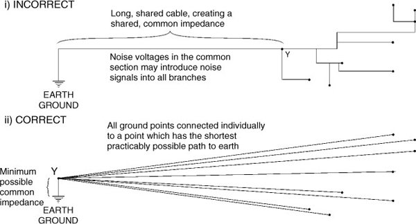
The section of the cable between point Y and earth, in each case forms the lower half of a potential divider between the individual earthing points and earth ground. The impedance of this section should be minimised, which means that the series components of resistance and inductance should be carefully considered. As we are dealing with AC, it is futile using a path of minimum resistance if the inductance is still allowed to remain high. In the case of power wiring, the close coupling of the individual cables for live and neutral can be used to help to cancel the inductance in each strand, but with single earth (ground) cables this option is not available, so short runs are the only real option.
Figure 25.1 Grounding
Incidentally, the terms earthing and grounding, which frequently get interchanged, may also have different meanings in different countries. Often, they are one and the same thing, but, strictly speaking, the chassis of an aeroplane can be the ground for all the electronic systems, even though in flight the aeroplane is not connected to the earth. The ground, in general, is the common reference plane for the electrical/electronic circuits, whether or not it is physically connected to the earth. In fact, in some audio installations, the audio ground may be separated from earth by a suitable impedance. Normally, however, in order to overwhelm the effects of any differences in ground potentials due to leakage inductances and capacitances to earth, a low impedance connection is made from the ground plane to the physical earth of the planet. Furthermore, if all metal chassis are earth grounded, then they cannot become lethal in the event of a loose live wire touching them – a fuse or a breaker merely blows, and not a human being.
Geography, or rather local geology, can also play a great part in the effectiveness of earthing systems, and if a studio is sited in a region of poor ground conductivity then little can usually be done about it. However, when the audio system interfacing is carefully and correctly terminated, the necessity for an excellent earth is usually significantly reduced. On the other hand, when the earthing system is excellent, an audio system may stand a better chance of tolerating less than optimum audio interfacing without the manifestation of too many problems. Obviously, though, one should strive to get both aspects as good as one can.
The general level of electromagnetic interference has risen in recent years to a point where we now seem to be swamped with it. The amount of radio traffic is now enormous, which has polluted the air with electromagnetic signals of all sorts. Even in the earth, surprisingly large noise currents can flow near to railway lines where digital signalling and control equipment is used. In industrial areas, there can also now be enormous amounts of electromagnetic pollution in the air, in the ground, and in the mains electricity supply. Staying clear of all this is not an easy task, but by paying due attention to each potential source, the effects can usually be reduced to insignificant levels. Unfortunately, the types of equipment often found in low budget studios tend to be more prone to external interference than top-of-the-line equipment. This problem is compounded by the fact that the level of knowledge about how to deal with the noises is less readily found in the smaller studios. This now often leads to situations where the studios which are least equipped to deal with these problems are the ones which most need to do so.
Good audio interfacing practices and good earthing practices can go a long way to reducing interference problems, but they may be able to do little about mains-borne interference. The European Union and other authorities around the world have already introduced legislation which restricts both the amount of interference which equipment can generate, and its sensitivity to it, but this will take years to take real effect. In fact, due to the seemingly endless growth of the use of electrical and electronic equipment, much of the legislation may only serve to slow down the rate of growth of electro-magnetic pollution, rather than to actually reduce it from present levels. The two cardinal rules are to ensure that studio equipment is supplied with the lowest practicably achievable source impedance for its electricity supply, and to keep all the interconnected equipment on the same phase. Figure 25.2 illustrates a right and a wrong way of installing power wiring if interference problems are to be avoided.
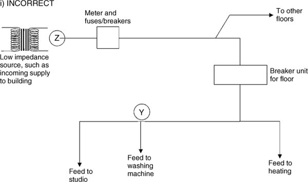
In the above arrangement, the long, shared section of the supply between points Y and Z serves to increase the impedance of the supply to the studio. Electrical loads on the other floors, together with current taken by the heating and other devices, will cause the voltage at Y to fluctuate as the current demand varies. Furthermore, interference caused by the washing machine motor will be superimposed on the supply line to the studio. The result would be a dirty and unstable supply to the studio when other electrical systems in the building were in use.
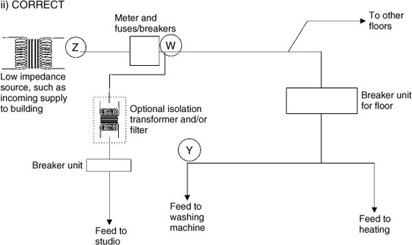
Here, the studio is fed directly from the meter at the incoming supply to the building, via over-sized cable. Whilst the voltage at point Y may still vary as other equipment in the building is turned on and off, the studio feed, from point W, will take advantage of the stability of the low impedance supply and will remain relatively stable. The section Z-W, which is of only minimum length and impedance, will form the lower half of a potential divider, Y-W-Z, with most of any interference from washing machine motors, or similar devices, being dissipated in the upper portion, Y-W. This solution may be seen as ‘inconvenient’ by the electrical installer, and unnecessarily expensive from a conventional power wiring point of view, but it may be the only way to ensure an adequate supply to sensitive recording equipment.
Figure 25.2 Power distribution
25.2 Low Impedance Supplies
Many pieces of equipment used in studios, such as most power amplifiers, are notorious for drawing current in surges. Figure 25.3 shows the typical way that an amplifier (other than the inefficient, constant output-stage current, Class A designs) will draw a large transient current from the mains in response to a loud bass drum signal being driven into the loudspeakers. The amplifier will initially draw current from the reservoir capacitors in its power supply, but once the voltage rails fall below the level where the peak voltage on the input rectifier exceeds it, large currents may begin to flow to replenish the reservoirs. The power drain from the electricity supply is therefore not continuous, but a continual series of high current pulses. As the supply impedance is in series with the amplifier, a potential divider will be formed, with the amplifier being the lower element. When the amplifier calls for a current surge, its mains input impedance will drop, and unless the power source is of a significantly lower impedance, the mains supply voltage measured at the wall socket will decrease as each pulse is drawn. Switchmode power supplies can also be very demanding, as shown in Figure 25.4, creating the same voltage sags as shown in Figure 25.3.
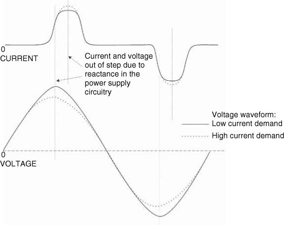
In the case of a stable, resistive load, such as an electric heater, the current demand would follow the sinusoidal waveform of the voltage, and both would be in phase. An audio power amplifier, however, presents a very different load to the supply. Due to the presence of inductance and capacitance in its power supply circuitry, it will present a partially reactive load to the supply, in which the current and voltage peaks will be displaced in phase. What is more, the current demand will not be sinusoidal, but will be more like the waveform shown above.
As the output stages of the amplifier supply power to the loudspeakers, they will deplete the charge in the reservoir capacitors. In a conventional power supply, the capacitors will be replenished via a transformer and bridge rectifier, but the bridge cannot begin to conduct until the voltage on the AC side exceeds the DC voltage on the capacitors. This means that as the AC voltage rises from zero, no current will be drawn until the voltage on the transformer secondary winding exceeds the residual voltage in the capacitors. The above figure shows no current initially being drawn, followed by a sudden rush of current once the DC voltage level is matched. Once the AC input voltage of the rectifier falls below the charge voltage on the capacitors the current then ceases, relatively abruptly. Note that as the current demand increases, the voltage falls, as shown by the dotted lines. The amount of voltage drop is dependent upon the supply impedance. A supply of zero impedance would suffer no voltage drop, which is why very low impedance supplies are often referred to as constant voltage sources.
The dotted lines in the current plot show the likely demand from a zero impedance supply, but the impedance of a poor supply would limit the current which can be drawn. This would cause the voltage to sag, and could cause the voltage on the studio power outlets to look something like the dotted lines on the voltage plot. This, in turn, produces harmonics on the supply voltage, which can extend into the hundreds of kilohertz region. Such harmonics can easily enter recording equipment, creating harsh sounds, and can play havoc with computer systems.
It is necessary to bear in mind that when current is drawn in this way, it is not as would be calculated by a simple V× I calculation. For example, a heater consuming 1 kW from a 230 volt supply would draw 4.35 amperes. However, if current was only being drawn 25% of the time, as could be the case with an amplifier, then 1 kW (or rather 1 kVA) would draw 17.4 amperes. Fromthe point of view of an electrician, a 5ampcable would suffice, because the time-averaged heating effect in both of the above cases is the same. The need for oversized cabling in studios is thus not due to cable heating or power consumption, but to avoid the voltage drop associated with the high current pulses, as these cause the voltage waveform distortion which gives rise to the intrusive harmonics.
Figure 25.3 Current and Voltage interaction. Current demand cycle of a typical power amplifier under heavy drive conditions
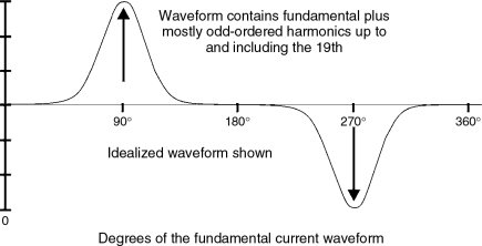
Figure 25.4 Current and Voltage interaction. Typical high-peak-current waveform for switch-mode power supply input on mains power circuit (after W.H. Lewis)
It matters naught whether or not there is a power conditioner on the mains input to the studio, because these harmonics, which can extend up to quite high frequencies, are being generated locally, and so they will have the same effect as any externally generated harmonics entering via a non-conditioned mains electricity supply. Harmonics on the supply can lead to a whole raft of problems, which will be discussed as this chapter progresses. However, if the supply impedance is low enough it will tend towards acting as a constant voltage source, and within reasonable limits will continue to supply a clean waveform even when high current demands are made. This is exactly akin to an amplifier with a high damping factor acting as a constant voltage source to the varying load which is characteristic of most loudspeakers. Sonically, this means more punch in the bass response, but, unless the amplifier itself draws current from a low impedance supply, the punch may be lost if its own power supply is depleted by the transient signals, especially when working near to its power output limits.
The power supplies of many pieces of equipment are not very good at filtering out higher harmonics on the mains. In all transformers, there exist leakage capacitances between the windings, and these can act as easy routes for the high frequency harmonics to enter the signal circuits. In analogue audio equipment they can cause harshness in the sound, but, somewhat surprisingly to many people, in digital equipment they can cause glitches and even crashes. They can also introduce errors into control circuits, and jitter into digital audio signals. It is remarkable how many such problems can be solved by using a low impedance supply.
Wherever possible, a studio should draw its mains supply directly from the electricity company’s input to the building, and not from any branch circuits. It should not share any cable run with any other part of the building, and the audio supply should not even share any cable runs with the studio’s own air conditioning units or refrigerators. It is also worth using the heaviest sensible gauge of wire, even if the fusing is much below this rating. This one can sometimes be difficult to get the electricians to understand, as, to many of them, power is power, and cables and fuses go hand in hand. Electricians may often frown strangely when asked to supply a fused, 50-amp feed with cable rated at 100 amps or more, but when the reasons are explained they are usually willing to comply. The situation is analogous to using loudspeaker cables of much higher current rating than is necessary for the continuous rated power handling of the loudspeakers. The rules, in fact, are identical: to supply the loudspeaker, or the studio, with the shortest, lowest impedance cables which can be practically realised.
Impedance is the mixture of resistance and reactance which is presented to an alternating current. It is the combination of the DC resistance, which can be measured by an ohm-meter, and the inductive and capacitive reactances. This can fool many people. A short, thin, closely intertwined pair of cables may possess an identical resistance to a longer, fatter, spacedapart pair, but the former may possess a lower impedance than the latter. Inductance is an electro-magnetic phenomenon which tends to cancel as the pair of wires forming the circuit are brought closer together, because the equal and opposite magnetic fields tend to cancel. The capacitance between the cables will increase as they are brought closer together, but this is a parallel phenomenon, whereas the inductive reactance is in series with the DC resistance. In practice, at power supply and audio frequencies, and especially with cables of typical studio lengths, the capacitive effects are negligible.
From the point of view of both power wiring and loudspeaker cabling, cables sharing the same outer jacket, and hence which are closely physically coupled, tend towards having the lowest impedances, and hence are best suited to studio use. In many countries, earth wires are also required to lie close to the live and neutral cables. It is hard to find specific data on this, but it is believed that the impedance of the earth wires tends also to be reduced by this method of dressing, and there is less chance of stray currents activating differential circuit breakers. Nevertheless, obtaining the lowest possible impedance path to the earth point, from each piece of equipment, is something that should be sought. The earthing system should also follow the same rules as the live and neutral feeds, in that the earth wire should share no common length of cable with any other building earth, as was shown in Figure 25.1 (ii).
25.3 The Number of Phases
In some countries, anything other than a mono-phase connection would be prohibited by regulations which state that no pieces of single phase equipment connected to different phases can be installed within the distance of the spread of a person’s arms. This is so that the two pieces cannot be touched simultaneously. On the other hand, in southern Europe, it is still not unusual to find 12-way plugboards installed inside studio equipment racks with four sockets connected to each of the three phases,1 and these have been installed by licensed electricians. Even in France, it has not been unusual to find a multitrack tape recorder on one phase and its associated mixing console on another phase. Noise levels under such circumstances are rarely satisfactory. In some cases, to have been able to supply one phase to the studio with capacity enough to supply all the equipment would have meant re-wiring the whole mains supply system within the building, which the owners were not prepared to do.
Electricity companies supply three phases because it is a much more efficient way both to generate and to distribute electricity in large quantities. Just as multi-cylinder piston engines run smoother than their similar sized, single cylinder counterparts, so three phase generators run smoother and more efficiently than single-phase generators, in which the electromagnetic effects of each revolution are less balanced. When power can be balanced across three phases it requires less cable to distribute it, because any neutral cables carry composite currents which are not in-phase, and so do not produce the cable heating effect of the total current passing in three, single-phase, neutral ‘returns’. More efficient generators and distribution mean less costs to the electricity companies, and hence cheaper electricity for the users.
The United Kingdom is a relatively rich, industrial country, with plenty of electricity and a culture in which concepts of safety are deeply entrenched. It is quite normal for a single domestic dwelling (house or flat [apartment]) to have a single phase 100 amp supply. In Iberia, on the other hand, where electricity is in short supply, a whole house may be limited to a 15 amp, single-phase supply, and many commercial premises may only have a 20 amp, three-phase supply. Requests for more power can incur large installation costs and a heavy surcharge on each subsequent bill. The British requirement for a single phase supply to all interconnected pieces of audio and/or video equipment is based on the premise that as potentials of around 400 volts can exist between phases, then equipment insulation could be more likely to break down when interconnected equipment is fed from different phases, as compared to being fed from a single, nominally 230 volt supply. What is more, the effects of any breakdown across different phases would be potentially more lethal than a breakdown on a single-phase supply. The Iberian philosophy seems to be ‘That is all that we have got – take it, or leave it’. The French, no doubt, explain it with the ubiquitous ‘Gallic shrug’. In fact, in the United States, there are many bi-phase supplies, derived from the two half-windings of a centre-tapped transformer, giving 120 volts from each half; frequently with one half going to each of a pair of adjacent houses. Internationally, these things are far from standardised.
25.3.1 Why One Phase Only?
Anyhow, the science behind all of this is not a variable, and it is for good reasons that a single phase supply is needed. If all the studio equipment were to be operated split across three phases, then all would be quiet as long as the three phases were supplying pure sine waves and were taking equal current. However, perfect sine waveforms on mains electricity supplies are somewhat rare, and studio equipment is not like the three balanced windings of a three-phase electric motor. It does not draw constant current because things are being turned on and off, such as tape machine motors, or have variable current demands such as most power amplifiers when music signals are passing through them. Current imbalances produce harmonics, and strange currents can be created in the common neutral wire. This subject is dealt with in great detail in two of the books listed in the bibliography at the end of the chapter. To quote from the Davis and Davis book (1997, p. 394) ‘It can be seen that noise generated by the power system can be minimised if only a single-phase power system is used throughout the electronic equipment’. To quote from the Giddings book (1995, pp. 54–56) ‘Another issue regarding AC power is the number of phases that are being used to drive the audio system. The ideal number is one, because of the capacitive coupling between most electronic equipment’s case and the power supply within. This coupling creates a voltage fluctuation at the line frequency on the case, which is usually the ground reference for the electronics within Pieces of equipment on the same phase will have a similar oscillating ground-reference, so they tend to cancel. If a second piece of equipment operating on a different phase is interconnected with these, a small voltage difference exists in the ground references due to the phase differences, and can be picked up as commonmode ground noise by the input, and amplified The more often the signal passes between pieces of equipment powered by different phases, and the greater the gains of this equipment, the more the problem is compounded’.
Over many years now, the method of power distribution that has been used in many good quality studios is to power all of the audio equipment from one phase, all the single-phase air conditioning, or heating, on another phase, and the lights, ventilation, and general power (to the office, etc.) on the third phase. If one phase is obviously cleaner or more stable than the others, then this one should be chosen for the audio. However, this should be periodically checked, as circumstances can change as a result of modifications in adjacent buildings.
25.4 Line Filters and Power Conditioners
As mentioned earlier in this chapter, it can be of little use conditioning the incoming power if there are pieces of equipment within the system which are introducing electromagnetic interference (EMI). Nevertheless, additional filtering of the supply ought to do no harm. The trouble is that so many EMI or RFI (Radio Frequency Interference) filters (or suppressers) fail to dispose of the problems, and merely result in dumping even more electrical hash on the earthing system. Figure 25.5 shows how this can commonly take place. In fact, the notion that uninterruptible power supplies will supply an absolutely clean supply is often very misguided. Only units with internal output voltage feedback control will ensure a clean waveform, and such units often need to be of substantially higher capacity than initially assumed, or even they may cause more problems than they solve. The problem is that they rarely have sufficiently low output impedances to ensure freedom from the production of harmonics by mechanisms such as power amplifier transient demands. Some of these things can actually cause computer crashes unless they are connected to individual computers without any other equipment sharing the supply. (For readers unfamiliar with these mechanisms, a careful re-assessment of Figure 25.3 could be useful.)
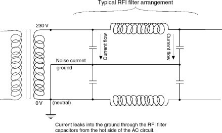
Figure 25.5 RFI filters in unbalanced circuits. Radio interference (RFI) filters can often remove much noise from the AC supply, only to dump most of it on the ground, which may be equally noise-sensitive: ‘Out of the frying pan, into the fire!’
25.5 Balanced Power
Figure 25.6 shows the balanced equivalent of Figure 25.5. The drawing was taken from an article by Martin Glassband,2 the author of the 1996 amendment to the United States National Electrical Code (Sections 530––70 to 530–73).
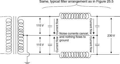
Figure 25.6 RFI filters in balanced circuits. The grounded centre tap on the AC transformer provides grounding for the AC system and balances the leakage currents to ground, thereby eliminating capacitive leakage from RFI filters as a source of objectionable ground currents, and the consequential noise
It has long been known that supplying sensitive audio equipment from a balanced power source can resolve many noise problems. The essence is to use a centre-tapped transformer supplying two supplies of opposite polarity, each of half of the total voltage. For example, a 230V supply is replaced by a centre-tapped supply, supplying two 115V ‘halves’ balanced around the centre tap which is taken to earth. Figure 25.7 shows how difficult reactive current problems can also be nullified by balancing the power feeds. In some countries, to supply the standard wall sockets of a building in such a way may be prohibited by local regulations, but in many cases no problem exists if alternative types of sockets are used for the balanced power.
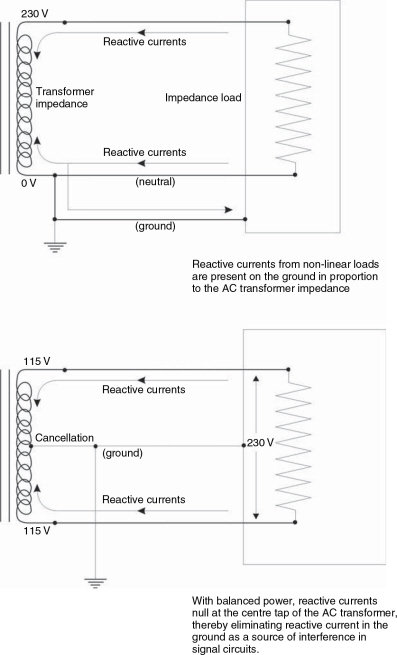
Figure 25.7 Comparison of behaviour of reactive load currents in unbalanced and balanced AC systems
In the United States, the fact was recognised in the late 1980s that certain high technology systems were so sensitive that conventional electricity supplies were limiting their performance. In 1996, there was an amendment added to the US National Electrical Code which allowed audio-video and similar installations to be run from balanced power systems as long as certain specific conditions were met. In other countries, after due explanation, it may be possible to persuade the local electrical safety people of the necessity of power balancing. On the other hand, as such codes relate only to systems installed within the structures of buildings, it may be possible to use a balancing transformer as a free-standing unit, feeding the plugboards to which the audio equipment is connected. This is not something which should be undertaken without expert advise, however, because the use of isolation transformers might defeat the operation of differential circuit-breakers, which are essential safety features in many installations. Further protection will likely be necessary on the isolated side of the wiring.
There are now many installations in which balanced power has been used, and the benefits can be quite wide-ranging. Studios with historic problems of noise have reported over 15 dB less interference pick-up. Due to the ability of balanced power systems to null high frequency interference in a way that is almost unachievable in conventional systems, jitter has been reduced in digital circuits, allowing much cleaner audio signals. The measured reduction in jitter has sometimes been more than 30%. There is also an effect on capacitive interference, because the effects of an electric field are related to the square of the voltage. A nominally 230 volt balanced system can only be 115 volts away from ground, compared to the 230 volts of an unbalanced system. (Or 60V instead of 120V in some countries.) Halving the voltage to ground therefore reduces the interference strength by 22, or four times. Balanced supplies can be very effective even in the most arduous of circumstances.
One reason why balanced power is so appropriate to smaller studios is that, unlike fully professional studios, they are very likely to have the sort of equipment mix which does not easily lend itself to optimal audio interfacing. They may be using mixed signal levels, many balanced to unbalanced connections, and much equipment that is only marginally engineered in the first place. Power balancing is also appropriate because lower budget studios are often sited in buildings where dedicated earths and low impedance mains supplies are difficult to arrange. They may also be in remote areas, at the end of long power lines, or on the 21st floor of a building where a good earth can be hard to achieve. Remember, though, never to attempt any electrical modification without the aid of a qualified electrician. Lives are at risk!
25.6 A General Overview
Whilst it is way outside the scope of this book to go into details of how to make special earthing or power supply arrangements, hopefully this chapter can at least stimulate awareness of the range of problems and solutions. Indeed, it would be totally irresponsible to encourage non-specialised personnel to attempt to make any changes on such safety related issues. Anybody who is particularly interested in the subject should refer to the books mentioned in the Bibliography at the end of the chapter, which explain very clearly just how deep and complex the subjects are.
The main point to be made in this chapter is that a good, clean mains supply and earth are not to be expected from a simple, domestic supply outlet. Many more computer crashes are caused by power problems that are ever realised, and software is often blamed when it is not at fault (although very frequently it is). Many noises are blamed on poor earths when they may actually be caused by poor mains, and vice versa. Many power conditioners do not provide the degree of cleanliness that their users believe they will deliver, and many uninterruptible supplies are not as free from mains-borne interference as they would lead their users to expect.
Once again, domestic and semi-professional equipment may be much more prone to disturbances by poor mains supplies and earthing arrangements than their fully professional counterparts, yet they may be the very pieces of equipment which are most likely to be used in less than optimum conditions. One thing which must be borne in mind, though, is that the fixing of poor mains supplies and earthing, to get the best out of semi-professional equipment, may be more expensive than buying professional equipment which may be more tolerant of poorer supply conditions.
25.7 Summary
The precise nature of earthing systems can depend on local geology and regulations.
Even in the earth, interference currents can now be very high, especially in industrial areas or near electrical transport systems.
One of the best protections against ‘earthing’ problems is to ensure low impedance mains supplies.
Harmonics on mains power supplies can be very detrimental to system performance.
Studio power wiring should be taken from the primary inlet to the building. Sensitive and interconnected equipment should all be connected to the same phase.
Line filters and power conditioners can actually create problems if they are not installed with a full understanding of how they work.
Balancing the power can be highly beneficial in circumstances of high mains-borne interference levels.
No power wiring should ever be installed or modified without reference to a qualified electrician who is knowledgeable of local conditions and regulations.
References
1 Newell, P. R., ‘Namouche’, Studio Sound, Vol. 36, No. 12, p. 48 (December 1994)
2 Glassband, Martin, ‘The Origin of Balanced Power’, Sound and Video Contractor, pp. 54–60 (September 1997)
‘Sound and Video Contractor’ [P.O. Box 12901 Overland Park, KS 66282-2901 USA] (September 1997). Issue dedicated to power quality
Giddings, P., Audio System Design and Installation, Focal Press, Boston USA and Oxford UK (1995). Previously published by Howard W. Sams. Indianapolis, IN, USA (1990)
Davis, D., Davis, C., Sound System Engineering, Second Edition, Focal Press, Boston, MA, USA (1997)