
CHAPTER 3
Sound Isolation
The weight of air. Interaction of the air vibrations with room boundaries. Reflexion, transmission and absorption. Reflexion and absorption as a means of isolation. The mass law, damping and decoupling. Frequency dependence of isolation needs. Level dependence of isolation needs vis-à-vis the non-uniform ear response. Floor, wall and ceiling isolation. Weight considerations. Material densities. The journey through a complex isolation system. Considerations regarding impact noises. Matters influencing studio location choice. The behaviour of mass/spring floor systems and the characteristics of fibrous and cellular base layers.
3.1 Vibrational Behaviour
Sound waves in air can be remarkably difficult to stop. Air is a fluid of considerable substance. It can support 500 tonne aeroplanes and blow down buildings. In fact, it is much heavier than most people think. On Earth, at sea level, air weighs about 1.2 kg per cubic metre, which is a very good reason for pumping any unnecessary excess of it out of aeroplanes (depressurising). This process is partially carried out to reduce the pressure differential stresses on the aircraft fuselage when flying at altitude in air of lower pressure (and density), but the aircraft also use less fuel by not having to carry excessive quantities of air over their entire journeys. A jumbo jet can actually reduce its load by around half a tonne by depressurising to an equivalent pressure altitude of around 8000 feet (2500 m). Air is also a rather springy substance, which makes it useful in air-pistols, shock absorbers and car tyres.
When any material is immersed in a vibrating fluid, it will itself be set into vibration to some degree. The characteristics of the resulting vibration will depend on the properties of the material, especially as, unlike air, the speed of sound is frequency dependent in many materials. The ‘laser gun’ sound sometimes heard from railway tracks when a train is approaching is due to phase dispersion within the steel tracks. The high frequencies travel faster than the low frequencies when the wheel flanges excite the rail modes, and so arrive first, with the lower frequencies following later.
An acoustic wave when travelling through air will continue to expand until it reaches a discontinuity, which may be a solid boundary or a porous material. It will then encounter a change in acoustic impedance that will cause some of the energy to be reflected, some to be absorbed, and some to be transmitted beyond the discontinuity. The degree of reflexion will be determined by the lack of acoustic permeability of the boundary and the degree of internal losses that will tend to convert the acoustic energy into heat. A rigid, heavy, impermeable structure, such as could be made from a 1 m thickness of reinforced concrete with a well-sealed surface, would reflect back perhaps 99.9% of the incident energy. Conversely, a wall of 1 m wedges of open-cell foam or mineral wool would present a very gradual impedance change which would allow the acoustic wave to enter with minimum reflexion, perhaps absorbing 99.9% of the incident energy. Mechanisms such as internal friction, tortuosity, and adiabatic losses convert acoustic energy into heat. The internal friction results in losses as the materials, on a molecular or particulate level, rub together. The energy required for these motions is taken from the acoustic energy.
Tortuosity relates to the degree of obstruction placed in the way of the air particles as they try to move under the influence of the acoustic wave. Air, in some circumstances, can act like a rather sticky, viscous fluid, and the viscous losses are increased as the degree of tortuosity increases. The fibres of a medium density mineral wool, for example, present a very tortuous path for the air vibration to negotiate. Remember, though, that there is no net air flow associated with these vibrations. The air particle motion is very localised, and is dependent upon the amplitude and frequency of the vibration. Adiabatic losses occur when the heat of compression and the cold of rarefaction, which both normally contribute to the sound propagation (see Chapter 4), are conducted away from the air by the close proximity of a porous medium in which the air is dispersed.
Because the above losses are proportional to the speed with which a particle of vibrating air tries to oscillate within the material, their absorption coefficients tend to be greater as the frequency rises due to the particle movements being more rapid. In addition, as the acoustic wave propagation must stop and reverse when it reaches a solid boundary, the particle motion will tend to zero when the boundary is approached. The absorbent effect of fibrous materials is therefore greater when the materials are placed some distance away from the reflective boundary. The particle velocity is greatest, and hence fibrous absorption is greatest, at the quarter and three-quarter wavelength distances from the boundary, on the velocity anti-nodes, which coincide with the pressure nodes of an acoustical wave. (See Chapter 4.)
Wave motion can be thought of like a swinging pendulum. When the pendulum is at its maximum height, the movement is zero, and when the movement is at its maximum velocity, the pendulum is swinging through its point of minimum height. The height is therefore at its maximum when the speed is at its minimum, and vice versa. Similarly, in an acoustic wave, the velocity component is at its maximum when the pressure component is at its minimum, and vice versa, and the energy in the propagation is continuously passing from one component to the other. This will also be discussed further in Chapter 4, because absorption will be seen to be more relevant to acoustic control than to isolation. When absorbent materials are used in isolation systems, they tend to be used more as mechanical springs and for acoustic damping. One reason for this is that fibrous/porous absorbers in general have little effect at low frequencies except in great depth and away from a reflective boundary. When we are considering sound isolation for recording studios, we tend to be considering treatment principally at low frequencies and near to boundaries, because preventing the acoustic energy from bass guitars and bass drums entering the boundaries is what we are largely seeking to achieve.
Once acoustic waves are allowed to enter a structure, things may become highly unpredictable. The disturbance will travel through the materials of the structure at their characteristic speeds of sound, sometimes with very little loss, then re-radiate into the air from the vibrating surfaces with unfathomable phase relationships that can produce ‘hot spots’ of sound energy in some very unexpected places. The speed of sound in solids is usually much greater than in air. For example, in concrete it is around 3500 m/s, in steel over 5000 m/s, and even in liquid water about 1500 m/s. In woods, the speed of sound can be dependent on the direction of propagation. Taking the case of beech, sound propagates along the grain at around 4500 m/s, yet at only just over 1100 m/s across the grain. These speeds are all approximate because the materials are somewhat variable in nature – fresh water and seawater, for instance – and there can be different speeds at different frequencies.
3.1.1 Relevance to Isolation
If isolation is the goal, then it is the degree of transmission through the boundaries that is important. From this point of view absorption and reflexions are often lumped together, because isolation will be achieved either by reflecting the energy back from a boundary or by absorption within it. Reflexion is by far the most important control technique, because absorbent walls would need to be of enormous thickness to be effective at low frequencies – several metres at 20 Hz, for example. In Chapter 2 it is mentioned that an anechoic chamber with 1 m wedges would absorb around 99.9% of the sound power down to 70 or 80 Hz or so, but such absorption is minimal in terms of isolation. Ninety-nine point nine per cent of the power being absorbed leaves only one part in 1000 of the original energy, but still only represents a 30 dB reduction (10 dB for each 10 times reduction). For measurement purposes, this renders reflexions insignificant in most cases, but 30 dB of isolation around a drum kit and bass guitar could still leave over 80 dB SPL on the other side of a 99.9% absorbent wall. To isolate by 60 dB we cannot allow more than one part in one million of the sound power to escape. Ten-metre thick walls of 70 kg/m3 mineral wool may suffice at 20 Hz, but it is hardly a practical solution, especially when one realises that the ceiling would need the same treatment.
3.2 Basic Isolation Concepts
There are essentially four aspects to sound isolation; mass, rigidity, damping and distance. Taking the last one first, if we can get far enough away from noise sources and our neighbours, then we will have solved our isolation problems. At least that seems to be rather obvious, but obvious things in acoustics are rather rare. The characteristics of mass, rigidity and damping are a little more complex.
All other things being equal, it takes more energy to move a large mass than a small one. Consequently, a large mass subjected to an acoustic wave will tend to reflect back more energy than a small mass, because it has more inertia. It has more acoustic impedance because it has a greater tendency to impede the path of the wave. However, if the mass is not rigid, and has a tendency to vibrate at its natural frequencies, energy may be absorbed from the acoustic wave that can set up resonances in the structure. Once the whole mass is resonating, its surfaces will be in movement and will act as diaphragms, re-radiating acoustic energy. If this mass were a wall, then the outer surface would selectively re-radiate the sound which was striking the inner surfaces. Isolation would therefore be dependent on the degree of the freedom of the mass to resonate.
If the mass were perfectly rigid, then resonances could not occur, because vibration implies movement, and infinite rigidity precludes this. Theoretically, of course, if a sealed room were made from an infinitely rigid, lightweight material, then because it could not vibrate it would be soundproof unless the whole thing could be set in movement en masse. In the latter case, the inertia of the air inside the room would resist the motion of the shell and set up pressure waves from the boundaries. Unfortunately, lightweight infinitely rigid materials do not exist, so the only way we can normally achieve high degrees of sound isolation over short distances is by the use of highly rigid, massive structures.
3.2.1 Damping and the Mass Law
A great influence on the ability of any structure to provide sound isolation is that of damping. Damping is the degree to which a propagating wave within a material or structure is internally absorbed, normally by the conversion of the vibrational energy into heat. The damping of a material or structure can also be achieved to some degree by the addition of a damping material to its surface – Plasticine on a bell, for example. An acoustically very ‘lossy’ (highly damped), massive structure can in many cases, for the same degree of isolation, be less rigid, because the passage of the vibrational waves through the structure is severely attenuated before the waves can re-radiate from another surface.
Limpness, to some degree, achieves the same end as rigidity – the inability of the structure or material to vibrate sympathetically – but unsupported limp materials are incapable of forming a structure – they have inertia, but no stiffness. This leads us to partitions that are essentially controlled by the mass law, which roughly states that when the inertia of a panel, rather than its stiffness, is the dominant principle for sound transmission loss, that loss increases by 6 dB for each doubling of the mass per unit area, and by 6 dB for each doubling of frequency. At least, that is, for plane waves at a given angle, this is why the mass law is only an approximation to normal circumstances.
3.2.2 Floating Structures
In practice, the means by which isolation is usually achieved is by mechanically decoupling the inner structure of a room from the main structure of the building. As has been discussed, isolation by pure absorption is very unwieldy – rooms made from 10 m thick mineral wool walls and ceilings are not an option. As no lightweight super-rigid structures are readily available, then neither is rigidity alone a practicable solution. To some degree, mass is used, but if it were to be used alone, then it too can become unrealistic in its application. For example, let us presume that a concrete block wall of 20 cm thickness and 40 dB isolation were to be augmented, by mass alone, to achieve 60 dB of isolation at low frequencies. The mass law would add at the most around 6 dB of isolation for each doubling of the mass per unit area, though the increasing rigidity of the more massive structure could tend to raise the isolation to above the 6 dB mark. Under ideal circumstances, which may not be realised in practice, doubling the thickness to 40 cm would yield 46 dB. Doubling this to 80 cm would result in 52 dB, and doubling this yet again to 1.6 m would still only provide 58 dB of isolation. We would therefore require walls of around 2 m thickness to achieve 60 dB of low frequency isolation if we were to rely on increasing the mass alone, and even this may be compromised by internal resonances within the structure.
The practical answer to the isolation problem lies in decoupling the inner and outer structures. This can be achieved by many means, such as steel springs, rubber or neoprene blocks, fibrous mats, polyurethane foams and other materials. There have even been cases of rooms floated on shredded car tyres, and even tennis balls, but the problem with tennis balls is that the air will gradually leak out over time. Re-inflatable air bags use the same principle, and this is another practical solution sometimes used.
The floating relies on the mass/spring/mass resonant system as shown in Figure 3.1. If the first mass is set in motion, the force exerted on the spring will be resisted by the inertia of the second mass, and above the resonant frequency of the system the spring will be heated by the vibrational energy. This converts the acoustic energy into thermal energy. Such isolation systems work down to about 1.4 times the resonant frequency of the system, below which the decoupling ceases to become effective. The resonant frequency is a function of the mass that is sprung and the stiffness of the springs. Increasing the mass and decreasing the spring stiffness both tend to reduce the resonant frequency.
The effect of this decoupling of the masses is to render the two systems (floated and structural) acoustically independent. Hence if we had a structure of 20 cm sand-filled concrete blocks, with 40 dB of low frequency isolation, we would only need an internal floated structure with 20 dB of isolation in order to achieve 60 dB of total isolation. This may be achieved by internal floated walls of 10 cm thickness, such as of sand-filled, concrete blocks, spring isolated from the floor, with a 5 cm mineral wool lined air space between the two walls. Such a system, as depicted in Figure 3.2, would achieve in a total thickness of 35 cm what could only be achieved by 2 m thickness of blocks that were mechanically connected, at least down to the resonant frequency of the floated system. Below that frequency, the isolation would begin to fall, and the advantage would pass back to the 2 m solid wall.
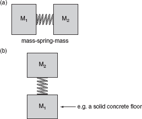
Figure 3.1:
(a) A resonant system; (b) If we now ‘earth’ M1 we will have a good representation of a floated floor, where M1 becomes of almost infinite impedance, such as would be the case for a heavy base slab on solid ground. If mass M2 were to be set in motion, say by pressing down on the mass and releasing it, the system would oscillate at its resonant frequency until all the energy was dissipated. The length of time for which the system oscillates depends on the resistive losses – the damping. If the mass M2 were caused to vibrate at a frequency above the resonant frequency of the system, the spring would effectively decouple the vibrations from the earthed mass, M1.
The way that this works is that the internal wall attenuates the sound from inside the room by 20 dB, which is the resultant level on the outside of the inner wall. The air between the walls acts as a spring and it is not capable of efficiently pushing or pulling the much greater mass of the inert outer wall. If the walls were in contact, the masses would be reasonably comparable, so the vibration in the inner layers would have relatively little trouble progressing through the structure. In the isolated wall system, it is only the sound pressure which has already been attenuated by 20 dB which impinges on the outer wall, which then attenuates the sound by another 40 dB before reaching the outside of the building, thus achieving the 60 dB of isolation. Figure 3.2 shows the inner wall floated on a layer of high-density mineral wool, which is an economical solution. However, a drawback is that as more weight is loaded on it with each layer of blocks, it compresses significantly. With a wall of 4m height it my go down from 10 cm to 6 cm, or thereabouts. This means that the whole room needs to be built with one entire layer of blocks at a time because if one whole wall is erected first, the first layers of blocks of the adjacent walls will not line up with those of the first wall which has already compressed the mineral wool below it. It is therefore essential when using mineral wool to make all the walls at the same time, row by row, so that the mineral wool compresses at the same rate. Until any lintels are in place above any doors or windows, some free-standing sections of wall may need to be supported by props, in order to keep them vertical.
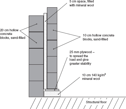
Figure 3.2:
Floating a wall – an earthed mass-spring-mass system in practice.
As an alternative, there are other isolation materials available made from materials such as neoprene and rubber. Sylomer and Clempol are typical examples, but the precise type of each material needs to be selected according to the total load which they will support. Somewhat confusingly, various manufacturers give the working loads in kg/m2, lb/ft2, lb/in2, kPa, kg/cm2, N/mm2 and other units of force. This can be totally confusing for non-specialists, and it is certainly not helpful for specialists, either. Nevertheless, they are all directly convertible.
Materials such as rubber and neoprene would typically be used in thicknesses of about 15 mm, and so would not compress as much as mineral wool during the construction of the walls. This allows a little more flexibility in the number of rows which can be laid at one time in each section of wall, because the compression range per row will be much less, but care should still be taken not to work too unevenly or hot-spots may be formed in some areas whilst other areas may be bridged over. It is, therefore, still best to build the rooms one entire row at a time.
3.2.3 Floating System Choices
The choice of what to use to float the inner structure depends on the mass to be floated and the lowest frequency to which isolation is needed. Two identical studio rooms, one for the recording of bass guitar and one for the recording of speech, both requiring the same degrees of isolation within the frequency range of their intended usages, would need rather different suspension systems if they were to be built in economically efficient ways. The former room would be much more expensive to build, and it would be a total waste of money to make a room such as this if so much low frequency isolation was unnecessary. For simplicity, let us make a comparison of two such rooms in which we are only interested in the sound leakage in the outward direction to a neighbouring room.
Taking the vocal recording room first, most of us will have experienced how the sound of speech can travel through walls. Noisy neighbours talking till late in the night whilst we are trying to get some sleep, either at home or in a holiday hotel, for example. This problem is so easy to solve that it is a disgrace that so many buildings have been constructed with so little thought about the problem. However, if a huge number of people want to go away on holiday as cheaply as possible, it is not too surprising that the hotels that they stay in will have been built as cheaply as possible. You often get what you pay for, but not much more.
People talking relatively loudly are likely to produce sound pressure levels in the order of 80 dB SPL (or the same dBA as there is little low frequency content) at the boundary of a room, a couple of metres from the source of the sound. (The speech frequencies, whose lower frequencies begin around 100 Hz, are little affected by the low frequency roll-off of the dBA weighting.) The deepest tones of some male voices extend down to 80 Hz or so, but they tend to be weak in level, and even with a little attenuation through a wall soon reduce to levels that become imperceptible. A glance at Figure 2.1 will reveal that at low frequencies at low levels the equal loudness curves close together. They do so to such a degree that only 5 dB or less reduction in SPL will produce a halving of subjective loudness as opposed to the 10 dB a mid frequency would require to produce the same effect. Therefore, 20 dB of isolation at 70 Hz and 50 dB of isolation at mid frequencies would render speech all but inaudible above a quiet background noise in an adjacent room. Figure 3.3 shows how this could typically be achieved. A person recording drama in an otherwise residential building would be unlikely to make the neighbours aware of their activities if such a treatment of the recording room were to be undertaken.
A musician wishing to practice playing bass guitar at home, in the same building as our drama studio, would not be so lucky. In this case, the fundamental frequencies of some 5-string basses can go down as far as 35 Hz. Enthusiastic playing could produce 100 dB SPL or more if it was for recording, where the sound of amplifier compression at high level can become an integral part of the sound. What is more, the relatively sustained notes of a bass guitar can exist for a sufficient period to excite strong structural resonances in an acoustically non-specifically designed construction, such as an apartment building.
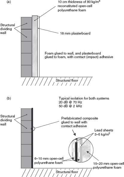
Figure 3.3:
Isolation treatments for direct application to walls: (a) With reflective surface to room; (b) With absorbent surface to room. Typical isolation for both systems: 20 dB at 70 Hz; 50 dB at 2 kHz.
From Figure 2.1 it can be seen that below about 55 dB SPL, 35 Hz is inaudible. If the bass guitarist were playing at a level of 80 dB at that frequency, then whether the room had 30 dB of isolation or 40 dB of isolation would make no difference, because in either case the resultant leakage at 35 Hz would be inaudible. Thirty dBA is usually considered to be an acceptable noise level for sleeping, and at 35 Hz, 30 dBA would actually be about 70 dB SPL (the 30 phon level in Figure 2.1) so in practice, even 10 dB of isolation at 35 Hz would suffice if the intention was not to annoy the neighbours. At 500 Hz, if the guitar were also producing 80 dB, then 50 dB of isolation would be the minimum needed in order not to annoy the neighbours with more than 30 dB of ‘noise’.
If the musician increased the volume by 30 dB, so that both the 35 Hz and 500 Hz components of the bass guitar were producing 110 dB, 30 dB extra isolation would be needed at both 35 Hz and 500 Hz to reduce the 110 dB down to a tolerable 30 phon (the 30 dBA curve equivalent) for the neighbours. However, because of the ear’s tendency to increase its sensitivity to low frequency level changes as the frequency descends, the provision of only 15 dB of extra isolation at both frequencies would not have an equal subjective effect. At 500 Hz, the 15 dB excess leakage would somewhat more than double the subjective ‘noise’ level for the neighbour (10 dB doubles loudness at mid frequencies) which, during the daytime and early evening, may be tolerated. Not so at 35 Hz, though. Figure 2.1 shows that at 35 Hz, 70 dB SPL lies about the 30 phon level. Increasing the SPL to 85 dB (the 15 dB extra leakage) now places 35 Hz on the 60 phon level. In other words, it will have subjectively doubled in loudness from the 30 to 40 phon curves, doubled again between the 40 and 50 phon curves, and doubled yet again between the 50 and 60 phon levels. The result would be an eight times increase in apparent loudness, which the neighbours simply may not tolerate.
What this means is that if the drama group begin to scream and shout and produce 30 dB more sound during the day, then they may well get away with an increase of isolation of only 15 dB in the mid and low frequencies, as they produce little low frequencies. However, the bass guitarist would not remain a friendly neighbour if the volume were to be increased by 30 dB with only 15 dB extra isolation being provided. What is worse is that low frequency isolation in structures is much less effective than high frequency isolation, because of the aforementioned mass law. (See Section 3.2.1.) Therefore, not only will the bass player need more isolation, but also the extra low frequency isolation needed will be much heavier than the equivalent mid frequency isolation. In a domestic building, the basic structure may simply not support the necessary weight of isolation materials, and so being a good neighbour whilst playing a bass guitar at 110 dB SPL may simply not be possible unless the other occupants of the building are deaf.
In practice, it may simply not be possible to provide adequate isolation for somebody who wants to play a bass guitar at 100 dB in a residential building if they are not on solid ground and where a very heavy internal structure can be built. Conversely, it may be possible for a drama group to make 100 dB of noise in a similar residential building without causing any nuisance after only a small amount of isolation work. The circumstances are very frequency dependent.
This variability in hearing sensitivity with level causes so much confusion for nonspecialists in the understanding of sound isolation requirements. Simple figures are not possible, as everything must relate to frequency and level. In effect, only curves of isolation requirements can be specified, dependent on the frequency range to be isolated and the levels to which they either will produce sound, or will need to be isolated from it. The seemingly simple question of ‘How many decibels of isolation do I need?’ usually has no simple answer.
Figure 1.1 shows an actual construction that was necessary to prevent bass guitars at around 110 dB from annoying the neighbours in a bedroom above. Looking at this and Figure 3.2 will show clearly the degree to which the isolation of low frequencies at high levels can get wildly out of hand in inappropriately chosen buildings. The room shown in Figure 1.1 weighs about 40 tonnes, and has a floor area of about 27 m2, so had it been on anything other than the ground floor – and on solid ground, with no basement – then it would not have been feasible to construct it in any normal domestic building. The only exception would have been if acoustic engineers could have got to the architects before the building was constructed, in order to suggest the type of reinforcement shown in Figure 1.2. If the premises were to be used for commercial recording, as was the case in Figures 1.1 and 1.2, then such isolation work might just be realistic, but purely for rehearsal it would normally (in fact in almost all cases) be economically out of the question. What often fails to be appreciated is that the sound waves do not know why they are being produced, so the isolation requirements do not change according to the use or the economic viability of their constraint. It is remarkable how many people believe that if they ‘only’ want to make the sound for personal fun the isolation will somehow cost less than if they were making the sound for commercially serious recording.
3.3 Practical Floors
Most floor isolation systems are based on the mass/spring/mass system shown in Figure 3.1, and some typical examples are shown in Figure 3.4. In each case the floated mass and the material used as the spring are different. Such options are necessary in order to achieve the required isolation, which may vary not only in the overall amount needed but also in the lowest frequency to which it must be effective. In general, however, the low frequency isolation reduces as the floated mass reduces, such as from (a) to (d) in Figure 3.4. For whatever requirements, the floor needs to be tuned so that its frequency of resonance is about half of that of the lowest frequency to be isolated. Also, whatever ‘spring’ is being used must be operating in its optimum load range. This concept is explained in Figure 3.5.
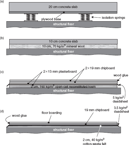
Figure 3.4:
A selection of floor-floating options.
It can therefore be seen that the springs cannot be chosen without an accurate knowledge of the weight that they will be supporting. In turn, the weight cannot be calculated until the structural requirements and the lowest frequency of required isolation are known. The choice of isolating springs may also depend on the floor which supports it; because obviously the springs which are spaced out over the surface of the floor present much higher point-loads on the supporting floor than do the ‘blanket’ coverings of fibrous materials or polyurethane foam panels (compare Figures 3.4 (a) and (b)). Figures 3.6 and 3.7 show the practical problems which may be encountered if the floor floating spring material is inappropriately chosen, even though the isolation achieved may be entirely adequate. These problems are not restricted to lightweight foams, however, as there have been cases of rooms built on 40 cm concrete slabs, and floated on very low frequency steel springs, which have tilted alarmingly when a heavy mixing console has been placed in an off-centre position when the rooms were equipped ready for use.

Figure 3.5:
Float materials need to be in the centre of their compression range for the most effective isolation.
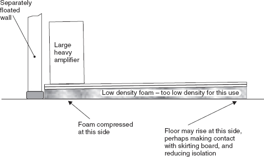
Figure 3.6:
Effect of uneven floor loading on low-density float material.
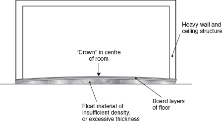
Figure 3.7:
Crown effect.
Vibration conduction via the ground can be considerable, but it is so dependent on the nature of the local terrain that it may be very difficult to predict or describe. Even a very massive rock and concrete floor can be set into vibration by a bass guitar amplifier in contact with it, so in all but the rarest of cases, a floated floor is mandatory for a professional recording studio. This is even more necessary if there is a potential for vibrations to enter the studio, such as may be the case with main roads or railways in the vicinity, or neighbouring factories with heavy, vibrating machinery.
As previously discussed, the low frequency isolation in terms of both the cut-off frequency and the degree of isolation will be dependent upon the type of recording to be undertaken. The isolation system shown in Figure 3.4(a) is typical of the large studios for full frequency range recording. The 20 cm concrete slab weighs about half a tonne per square metre, and the springs are chosen to support this weight in their mid-compression range, when the whole system will probably have a resonance of 5 to 8 Hz. The bases of the spring mounting frames (or boxes) will be likely to have an area of about 400 cm2, or 0.04 m2. If there were one spring for every 1 m2, then the load on each 0.04 m2 base would be 500 kg, which equates to a pressure of 12.5 tonnes per square metre immediately below the bases. Things like this must be taken into account when designing floor-floating systems. If such spot loads cannot be supported, then something must be done to spread the load. Likewise, the floated slab itself must usually have some load spreading, to avoid the tops of the springs punching through it. However, this is usually automatically a part of the construction, because the slab will need a continuous base over its entire area, above the springs, before it is cast. (See the plywood base in Figure 3.4(a).)
Whether the floated slab supports walls around its perimeter is largely dependent upon the weight of the perimeter walls. For a heavy concrete block isolation wall structure, such as shown in Figure 1.1, it would be typical to float it separately from the floated floor, and only to build the lighter weight acoustic control shell walls directly on the floated slab. Too much weight around the perimeter could lead to the crown effect shown in Figure 3.7 unless extra spring reinforcement were to be placed close to the edges of the slab. It is definitely preferable, however, with heavy structures, to float the walls separately on their own spring base, which makes the calculations and the construction much easier. It is also more flexible should modifications need to be made later. Furthermore, the heavy isolation walls may also have to carry the weight of a ceiling structure, so the downloads below the isolation wall can easily reach 5 or 10 tonnes per square metre, which is excessive in terms of being supported on the edges of a floated slab. In fact, there have been cases where a situation such as that shown in Figure 3.7 has occurred, and where the floated layer has been a reinforced concrete slab which has subsequently cracked open under the load. It is best to restrict the load on a floated slab to the internal acoustic control structures.
Figure 3.4(b) shows a 10 cm reinforced concrete slab floated on a mineral wool base ‘spring’. Using this technique, the load is evenly distributed over the entire supporting area. It is relatively simple to cast tubes in this type of floor to carry cables, even though the concrete is relatively thin, as shown in Figure 3.8. There can be advantages and disadvantages to this type of floating because, depending on circumstances, the continuous blanket of mineral wool can transmit more energy into the base slab by virtue of the greater area of contact, or it may improve matters due to the extra damping of the base slab. Certainly, if the floated floor is not on solid ground, such as if it were above a basement, the more even weight distribution of the continuous spring material may be advantageous structurally, even if not acoustically. In general, the discrete spring or elastomer block system of floating is acoustically superior to the fibrous blanket method. The discrete mountings allow an air cavity to exist between the slab and the structural floor, which can improve the isolation. Any such gap is usually damped with a light, uncompressed filling of mineral wool.
Figure 3.4(c) shows a composite floor made from multiple layers of heavy and limp materials, floated on a reconstituted polyurethane foam base. (The polyurethane foam is the sponge [open cell] type, not the aerosol type of closed cell expanding polyurethane foam, which has entirely different properties.) This system is useful where wet-work (cement) is impracticable. Such a floor sandwich would weigh about 50 kg/m2, which is about one fifth of the weight of a concrete slab of 10 cm thickness. For stability, and to avoid the effect shown in Figure 3.6, the foam spring layer would typically be 3 cm of 120 to 160 kg/m3 sponge. This type of floated floor exhibits less low frequency isolation than concrete floors, but can achieve what is often an adequate degree of isolation in circumstances where the floor loading is restricted. Many domestic buildings may only have total floor loading capabilities in the region of 120 kg/m2, which would be incapable of supporting even a 5 cm floated concrete slab. The density of concrete is typically around 2000 to 2500 kg/m3 so a 1 m square of 10 cm concrete slab would weigh around 250 kg. The typical light industrial loading for a building would be in the order of 400 kg/m2 (or 100 lb/ft2 in imperial measure). Table 3.1 shows the densities of some typical acoustic materials, plus a few others to provide some points of reference.
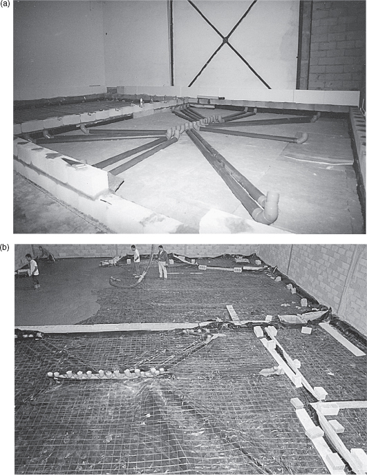
Figure 3.8:
Cable tubes: (a) If the 10 cm of mineral wool is composed of two layers of 5 cm, the upper layer can have channels cut into it to allow the tubes to be lowered on to the lower layer, thus positioning the tube half in the mineral wool and half in the concrete; (b) The tubes and mineral wool are covered in plastic sheeting and steel reinforcing mesh. The tube mouths can be seen protruding. They are blocked with mineral wool plugs prior to the pouring of the 10 to 15 cm concrete slab; (c) Detail of procedure.
Figure 3.4(d) shows a very light floating system. It consists of a wooden floor surface glued on top of a 19 mm layer of chipboard, floated on top of a composite of a 3.5 kg/m2 deadsheet and a 2 cm layer of cotton-waste felt. Deadsheets will be discussed further in Chapter 4 (see also Glossary), but they are essentially heavy, limp membranes used as damping layers. This type of floor is principally used to reduce the effect of impact noises from entering a structure. They are particularly useful above a weak ceiling where impact noises from footsteps could enter a structure and be rather difficult to treat from below, especially when the room below has only limited height, and hence not much room for treatment.
Table 3.1: Density of materials
Cork |
0.25 |
Pine |
0.45 |
Typical hardwoods |
0.60‒0.75 |
Plywood |
0.60‒0.70 |
Plasterboard |
0.75 |
Chipboard |
0.81 |
Water |
1.0 |
Dry sand |
1.5 |
Brick (solid) |
1.8 |
Glass |
2.4 |
Concrete |
1.8‒2.7 |
Aluminium |
2.7 |
Granite |
2.7 |
Slate |
2.9 |
Steel |
7.7 |
Iron |
7.8 |
Lead |
11.3 |
Gold |
19.3 |
Osmium (the densest element known) |
22.4 |
The figures are in grammes per cubic centimetre, but they also represent tonnes per cubic metre.
Figure 3.9 shows a range of isolators used for structural floating. It should now be apparent that the range of possibilities for floor floating is enormous, which is just as well because the range of different circumstances requiring floated floors is equally enormous.
3.3.1 Floors on Weak Sub-Floors
The situation of floor floating is complicated enormously when the structural floor is itself significantly resonant. Such can typically be the case when a ground floor studio is sited over an underground car park, or when studios are stacked one above the other in the same building. If the site under consideration as a potential studio building also has low ceilings, then the sound isolation problems can become impossible to solve without major reconstruction of the building. Isolation of floors and ceilings takes up space, as a considerable thickness of materials is needed in each case.
When structural floors are weak, it is very difficult to prevent low frequency noises (such as those caused by a bass drum on a floated floor) from passing through the spring layer and exciting the resonances in the floor below. If the floor is resonant, then it only requires a relatively small amount of energy to excite the natural frequencies of the structure. In many cases, the only way to overcome such difficulties would be to support another floor, on steel beams, above the main floor, but this can only be done in cases where the walls are strong enough to support the extra weight and when there is sufficient headroom to accept the loss of height. In the following section, these problems will arise again when we look at the problem of low headroom and weak ceilings, and it will also be discussed in Section 3.8.
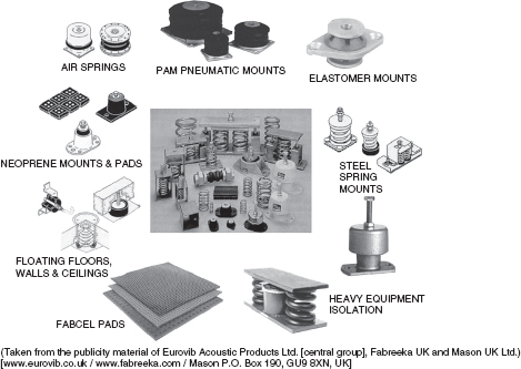
Figure 3.9:
Range of isolation mounts.
Essentially, a fundamental requirement for high isolation, unless large amounts of money or space are to be consumed, is that the entire outer shell of the chosen building should be massive, rigid and well damped. Steel, and cast concrete, often fail to provide the last of these three requirements; they can have characteristic resonances that weaken the isolation. However, steel reinforced concrete floors can be excellent when they are sufficiently strong, as the steel rods encased in the concrete can be effective in providing damping, but the situation can be improved further by the addition of damping agents to the wet concrete mix if the floors are to be cast from new. ‘Concredamp’, for example, is one proprietary brand of such a compound.
3.4 Ceiling Isolation
Reference, once again, to Figure 1.1 will show a range of techniques used for ceiling isolation. The need for this seemingly excessive collection of techniques was precipitated by the somewhat absurd decision by four Andalusians to site a recording studio, for 24 hours per day use by rock bands, directly under the bedroom of an unsympathetic neighbour in a building of unsuitably weak structure. Although, for clarity, the drawing is not exactly to scale, neither is it too far from scale. It does give, therefore, a reasonably realistic view of the amount of space lost to isolation and acoustic control.
Such a construction was only possible because the original space had (barely) adequate height – about 3.5 m – allowing about 1m for isolation and acoustic control before the inner fabric ceilings at 2.5 m. There is currently a tendency towards smaller and smaller studios as the perceived size requirement comes down by using hard disc-based recording and mixing systems. However, the size of human beings and acoustic wavelengths is not coming down, and as virtual studios do not replace conventional ones, there is a limit to how small one can go. The other force that is bearing down on studio size is an economic one. In many cases, as the real price of recording equipment of good sound quality comes down, an enormous number of people now seem to expect that the cost of recording acoustics should somehow fall accordingly. It is unlikely to do so, though; simply because economics have no bearing on the speed of sound or any other physical law, and it is the physical laws of acoustics that determine whether a room is well isolated or not – and also whether it is going to have good internal acoustics or not. There will be more on this subject in the following chapters, but there is definitely a tendency for people to underestimate the need for adequate ceiling height in order to make a good studio.
Given a starting height of only 3 m, it is almost impossible to install adequate ceiling isolation if the floor above is either noise sensitive or liable to radiate noises that can be prejudicial to the operation of the studio. The only exception is if the floor is truly massive, but this may only be of use in constraining sound within the studio. In the reverse direction, the vibrations in a floor that has considerable mass can be extremely difficult to stop from entering the space below unless an isolated ceiling can be employed which is suspended from floated walls, and not from the ceiling above. In Figure 1.1, an isolated plasterboard inner ceiling, above the acoustic control shell, can be seen suspended from a 6 cm layer of polyurethane sponge (reconstituted foam) which is in turn glued to a plasterboard/deadsheet/plasterboard sandwich fixed below wooden beams. These are supported on the floated concrete walls. In addition, to augment the transmission loss and to prevent resonances between the upper plasterboard layer and the plasterboard suspended from the upper ceiling, a mineral wool infill was used between the beams. There is therefore no physical contact between the structural ceiling and the intermediate isolation ceiling except via the air, and ultimately the ground, but this contact is decoupled by way of the suspension materials between the floated concrete isolation walls and the main structure. Furthermore, on the underside of the structural ceiling (the floor of the bedroom), a layer of 5 cm medium density mineral wool had been attached by a cement. Below that, also by means of a cement, a layer of 18 mm plasterboard had been suspended. A further isolation layer of two 13 mm plasterboards had been laid on top of the inner isolation structure.
One reason why so many different materials and suspension systems were used was to avoid any coincident resonances that can result from using too much of too few materials. Any resonances inherent in any structure or material will tend to reduce the isolation, perhaps seriously, at the resonant frequency. By using a variety of isolation techniques, the resonances will tend to occur at different frequencies, and hence any weak spots will be covered by the other material combinations in the different layers. A brief ‘ride’ on a sound wave attempting to propagate through the isolation ceiling may be usefully informative, as we can discuss the isolation mechanisms involved as we come across them.
3.4.1 A Trip Through the Ceiling
Before reading this subsection, it may be worthwhile photocopying Figure 1.1 and keeping it visible during the discussion. The description of the passage of an acoustic wave through the ceiling system should be informative because it will encounter the many different types of obstacles that have been built into this ceiling in order to try to achieve the desired isolation. An understanding of something of the feel for these isolation concepts is essential, because experience and knowledge of the practical application of these principles are perhaps the only real way of deciding on the most effective combination.
Even great academic acousticians acknowledge that ‘the theoretical analysis of the sound transmission through double leaf partitions is far less well developed than that of single leaf partitions, and that consequently greater reliance must be placed on empirical information’.1 Clearly, the ceiling construction that we are describing here is even more complex than a double leaf partition, so if any readers get any bright ideas about using their computers to solve these complex interactions – forget it! There are simply no programs to deal with this sort of thing, and even experts need to use a lot of discretion when using what limited computerised help they have. In the words of Fahy: ‘The reason is not hard to find; the complexity of construction and the correspondingly large number of parameters, some of which are difficult to evaluate, militate against the refinement of theoretical treatments’.1 Bearing this in mind, please forgive the following wordy treatment of the subject.
An acoustic wave originating in the recording space shown in Figure 1.1 and travelling in the direction of the ceiling would first pass through the lower layers of the inner ceiling, whose purpose is primarily for controlling the character of the sound within the room itself. The wave would next encounter the two layers of plasterboard fixed on top of the support beams of the inner acoustic shell. Plasterboard consists of a granular textured plaster core, covered with a layer of paper on each side to provide a degree of structural integrity. It is more resistant, less dense and less brittle than pure plaster sheet. High frequencies striking this surface would be almost entirely reflected back, because the plasterboard is reasonably heavy, having a density of about 750 kg/m3. The weight of a double layer, around 18 kg/m2, would be sufficient for the mass law, alone, to ensure that the highest frequencies were reflected back. As the frequencies lower, they will be progressively more able to enter the material and set it into vibration. To some degree, these vibrations will set the whole layer in motion, and the opposite surface will then re-radiate the vibrations into the air above. However, to a considerable degree, the particulate/granular nature of the core material will cause frictional losses as the vibrations pass through the material, turning acoustic energy into heat energy. The amount of energy available to re-radiate from the upper surface of the plasterboard will therefore have been reduced, and a degree of isolation will have been achieved. Figure 3.10 shows a typical loss-versus-frequency plot for this type of ceiling. However, the plot can only be taken as approximate, because the isolation provided by such structures is dependent upon their absolute surface area, their rigidity, and numerous other factors.
Not all the isolation is due to absorption, of course, because some is due to the energy being reflected back down towards the floor, but there will be progressively more absorption and transmission via re-radiation, as the frequency lowers and the reflectivity reduces. The overall transmission loss will include the reflexion and absorption, and the overall coefficient of absorption figure will include absorption and transmission. Essentially the isolation is what is not transmitted, and the absorption coefficient is what is not reflected. In fact, absorption is traditionally measured in units called sabins, after Wallace Clement Sabine, the pioneer of reverberation analysis, who himself first used ‘equivalent open window area’ as a unit of absorption. From this concept, it can be clearly understood how absorption can include transmission, because an open window converts almost no acoustic energy into heat. It transmits almost all of it to the other side.
One hundred per cent transmission = 100% absorption = zero reflexion. Zero transmission, achieved either by 100% absorption, 100% reflexion or some combination of the two, still amounts to 100% isolation. The loosely used terminology can be a little confusing, but absorption does get lumped into isolation and transmission figures, depending upon which one is of greatest importance in the context of the problems. Just to help to clarify things, a room of 1 m thick, smooth, solid concrete walls and ceiling would have excellent isolation, but very little absorption. It would tend to have a long reverberation time because the sound energy would be trapped inside of it. Almost nothing would escape. Conversely, a room of tissue paper in the middle of a desert would have very high absorption (and consequently almost no reverberation time), but almost no isolation, because all the energy would be either lost in the sand, or would be free to escape to the outside air.
Anyhow, let us now return to our discussion of Figure 1.1. The vibrational energy that is transmitted through the double plasterboard acoustic shell cap would then proceed across the air gap to the lower surface of the isolation shell ceiling. The acoustic wave would first pass through a layer of 2 cm cotton waste felt, bonded to a 3.5 kg/m2 layer of an acoustic deadsheet (see Glossary). Here we encounter an additional, loosely coupled mass layer with the absorbent felt layer uppermost, in the air gap. The function of these layers is to damp resonances in both the plasterboard and the air. The high viscous losses in the deadsheet tend to suppress any high (see Glossary) resonances in the plasterboard, and the fibrous absorption characteristics of the felt will tend to damp down any cavity resonances, caused by the hard parallel surfaces of the upper surface of the control shell and the lower surface of the isolation shell.
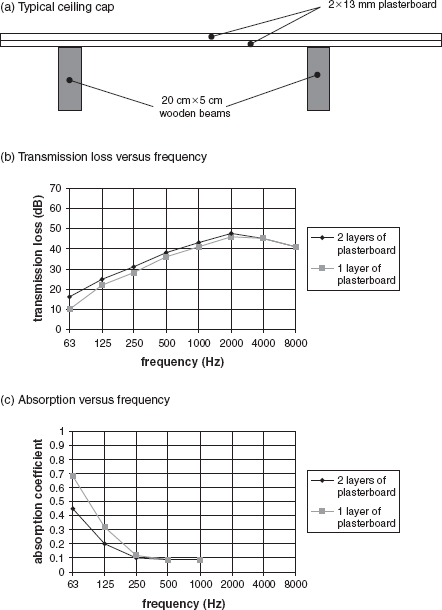
Figure 3.10:
Acoustic performance of a typical ceiling cap: (a) Typical ceiling cap; (b) transmission loss versus frequency; (c) absorption versus frequency. Note how the addition of an extra layer of plasterboard increases the transmission loss (isolation), as shown in (b), but decreases the absorption, as shown in (c). The addition of a second layer adds more mass to the system and tends to make it more rigid. The effect is that the two layers become more reflective than the single layer. The additional layer therefore improves the isolation by means of reflecting more energy back into the room, but this will of course make the room more reflective or reverberant. If the decay time of the room with only one plasterboard installed was to be maintained after the addition of the second layer, more absorbent materials would need to be introduced into the room. Isolation and absorption are often confused by non-specialists, but this situation clearly demonstrates the difference.
The lower surface of the isolation shell is a classic mass/spring/mass combination, formed by a double layer of 13 mm plasterboard (the lower mass) connected, by contact adhesive only, to a 6 cm layer of reconstituted open cell polyurethane foam of 80 kg/m3 (the spring). This is in turn connected, by contact adhesive only, to the upper mass. In this case, the upper mass consists of a sandwich of two layers of plasterboard with a 5 kg/m2 deadsheet in between, nailed to a relatively heavy and rigid series of wooden support beams. The lower plasterboard layers are not in contact with the concrete block walls – there is a gap of a few millimetres all around. This mass layer is therefore free to vibrate, with its vibrations alternately applying compression and expansion forces on the polyurethane foam spring. Such a system might seem a little insecure, but in fact the foam can withstand traction forces of over 3 tonnes per square metre. With a good adhesive, there is little chance of the plasterboard causing problems, as the double layer weighs less than 20 kg/m2 – less than 1% of the traction limit.
Once again, the lower plasterboard layers will tend to reflect back the incident wave to a degree according to the frequency, and will absorb some of the energy in the internal frictional losses. However, this time its upper surface is not so free to radiate, because it is glued to a spongy foam. The foam will have the action of damping the vibration in the plasterboard, again rather like sticking Plasticine on a bell. The vibrations that do enter the foam layer will be strongly resisted by the mass and rigidity of the upper mass layer. The tendency, therefore, will be for the foam to compress and expand, rather than to move as a whole, and the internal frictional losses in the cellular construction of the foam will be very effective in converting the acoustical energy into heat. This action will be effective down to the resonant frequency of the spring thus loaded.
The upper mass layer acts as a low frequency barrier, and its effect is augmented by the rigidity imparted by the wooden beam structure. In this instance, the two layers of plasterboard sandwich a layer of a 5 kg/m2 deadsheet, the combination constituting what is known as a constrained layer system. The principle of the damping effect and additional acoustic losses due to the constrained layer are shown in Figure 3.11. Such a system will be reflective down to lower frequencies than the plasterboard alone, but it will also produce more absorption down to lower frequencies. It will certainly transmit less.
Whatever acoustic energy is left to propagate above the constrained layer will then cross the air gap between the wooden beams and proceed on to the layer of 18 mm plasterboard, attached to a layer of medium density mineral wool by adhesive cement. The mineral wool is itself then attached to the structural ceiling by the same cement-type adhesive. The air gap again contains mineral wool to suppress any cavity resonances, but it also acts as a velocity component absorber, as described in Section 3.1.
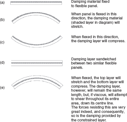
Figure 3.11:
Constrained-layer damping principle.
The plasterboard/mineral wool/structural ceiling combination, again, is a mass/spring/mass system. As mentioned previously, the reason for using different materials and thicknesses in this upper system was to avoid any weak spots caused by resonances that coincided with the resonances in the lower mass/spring/mass system. Once again, the upper mass of the structural floor acts to resist the bodily movement of the mineral wool spring as it is set in motion by the vibrational energy impinging on the lower mass of 18 mm plasterboard. By this time, the acoustic energy from the source in the recording room will have been reduced to such a degree that what remains to re-radiate into the bedroom is insufficient to create any disturbance to the sleep of the neighbours. By now, also, it will only consist of low frequencies – the highs will be virtually non-existent. If this all seems a little extreme, it must be borne in mind that in order to achieve even 60 dB of isolation, only one one-millionth of the sound power can be allowed to penetrate the barriers.
3.5 Summing the Results
So, from the individual isolation figures of the individual isolation systems we should be able to calculate the total isolation, but there are some practical circumstances which make calculations difficult unless many other factors are known.
If we have a noise source in the recording room, then it is of little help if we only know its output SPL in free-field (anechoic) conditions. If we know that a guitar amplifier can produce 110 dB SPL at 1m distance in a relatively dead room, it does not mean that it cannot produce more in other circumstances. If we were to take it into a very live room, the level of the direct signal would be augmented by all the reflexions, which could superimpose their energy on the direct sound and easily produce 6 or 8 dB more SPL. Therefore, we need to know the sound pressure levels that will be produced by instruments in the actual rooms which we need to isolate, and from this, it will be obvious that for any given sound source, a live room will need more isolation than a dead room. Quite simply if things sound louder in an acoustically live room, then the sound isolation requirements to an adjacent room will be correspondingly greater.
Conversely, if the receiving room is reverberant it will amplify, by means of reflected energy, the noises entering from an adjacent room. In a small bedroom, a double bed provides significant absorption, as do furniture and curtains. In the case that we have been discussing, the bedroom was well furnished, and the noise level measurements were taken at a point 50 cm above the bed. Had the room been stripped of all furnishings it would have become much more reverberant, so the 30 dBA measured after the isolation may then have risen to 35 dBA or so, which could be deemed to be unacceptable for the neighbours to sleep easily. Similarly, if the acoustic control treatment were to be removed from the recording room, rendering it much more reverberant, the maximum SPL produced in the room by typical instruments would also increase, and again the isolation shown in Figure 1.1 may no longer be adequate.
So many variables exist in acoustic control work, which is why it is often so difficult for acoustics engineers to give simple answers to what may appear to be simple questions. What has hopefully become obvious from the previous two sections is that there are often multiple processes at work simultaneously in a typical isolation system, and that they may interact in very complex ways.
3.5.1 Internal Reflexions
There is another reason why the simple summation of the calculated isolation provided by each individual section of the complete structure cannot be relied upon to give the isolation of the whole system. It is that internal reflexions can be set up between the layers, which can add re-reflected energy to the forward-going propagation. This is shown diagrammatically in Figure 3.12. The reduction of this effect requires fibrous layers in the various air spaces. Especially in existing buildings, where the exact nature of the structure is not known, a degree of ‘cut and try’ can be involved, even for very experienced acoustic engineers.
3.6 Wall Isolation
In general, walls are easier to isolate than floors or ceilings. Figure 3.13 shows a relatively simple solution, the addition of a heavy internal wall with a cavity between the isolation wall and the structural wall. There is usually little problem constructing walls of significantly greater mass per square metre than can be used in ceilings, for example. Floors, of course, will be in some sort of physical contact with the structure, via either springs or mats, but heavy ceilings need to be supported with massive beams or suspension systems, which can often be quite impracticable. A wall, however, as long as it has a solid floor below it, can usually be both very heavy and simple to construct. The only problem with the wall system in Figure 3.13(a) is the flanking transmission via the contacts at the floor and ceiling. This is simply avoided by the insertion of spring seals as shown in Figure 3.13(b).
Wall isolation is sometimes also made easier by the fact that the existing structural walls are often more massive than the floors (other than those built directly on the ground) and ceilings. Very effective wall isolation can be achieved by the use of floated concrete block walls filled with sand. These are especially effective if the structural walls are also massive and well damped. In new buildings, it can be advantageous to ask the architects to use sand-filled concrete blocks in the main structure. The combination of structural and floated wall systems so made, with a 5 or 10 cm air space between, can easily produce more than 70 dBA of isolation, which is extremely difficult to achieve in floor or ceiling isolation systems unless these can be used simultaneously, both above and below the structural ceilings and floors.
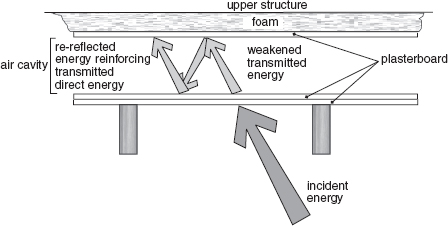
Figure 3.12:
Re-reflexion between layers. Resonant build up in an air cavity can reduce isolation in a similar way to which the build up of reverberant energy in a space can make a source louder than it would be in free-field conditions.
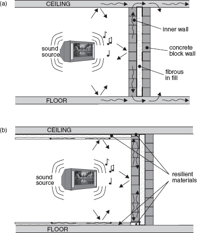
Figure 3.13:
The benefits of floating surfaces: (a) The addition of an inner wall to aid isolation between the rooms can be largely ineffective if flanking transmission via the floor and ceiling pass round it. What is more, resonances within the inner wall structure can themselves pass additional energy into the floor and ceiling, perhaps making matters worse at some frequencies; (b) Protecting the floor and ceiling from direct sound, plus floating the inner wall away from the walls, floor and ceiling, can greatly reduce the amount of sound passed into the structure, and hence to the neighbour.
In shared buildings, therefore, where access to the walls, floors and ceilings of neighbouring premises is not possible, wall isolation is by far the easiest to achieve in one-side-only treatments.
3.7 Lighter Weight Isolation Systems
In some circumstances, either only a limited degree of isolation is necessary, or moderate isolation is needed in buildings with weak floors. In such cases, systems such as those shown in Figure 3.14 can be used. The technique simply involves lining the entire room with open cell polyurethane foam (or mineral wool) of suitable density and thickness, and lining the interior with plasterboard. With low density spring materials (foam or mineral wool) on the walls and ceiling, the system resonances can be kept quite low. On the floor, however, low density materials would lead to instability, such as shown in Figure 3.6, so to keep the system resonances sufficiently low with the higher density spring, a correspondingly greater weight needs to be added. This can be achieved by laying concrete paving slabs on top of the floor covering, or even casting a reinforced concrete slab if it is feasible.
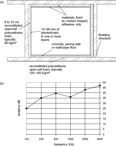
Figure 3.14:
Distributing the isolation load: (a) Typical construction. Isolation of this type can be very effective. The walls and ceiling bear much of the load, which can make this technique useful in premises with weak floors. Alternatively, a similar system can be used with mineral wool and a cement-based adhesive. (See Figure 1.1.) Contact adhesive gives a more instant bond, without the need for support during setting, but the noxious fumes can be a problem during construction; (b) The plot shows the typical extra isolation achieved by the sort of system shown in (a), above that provided by the basic building structure.
The results with this type of isolation system can be surprisingly good, though their resistance to the ingress of impact noise from outside the structure can be poor. The other benefit is that the weight is distributed about the room surfaces, and the whole load is not imposed on the floor. Even the walls carry some of the load, which can be very advantageous in weak buildings.
3.8 Reciprocity and Impact Noises
Notwithstanding certain restrictions, if we were to build two adjacent rooms with 60 dB of isolation between them, it would not make any difference which room contained the source of the sound and which was the receiving room. The isolation would remain the same, even though the order of materials in the isolation system may be asymmetrical, as shown in Figure 3.15. However, this only remains true for airborne sound, where the solid materials present an acoustic impedance much greater than that of the air because their densities are enormously different to that of air.
Figure 3.16 shows the vertical separation of two rooms, the lower one having an open cell foam/plasterboard ceiling isolation, which is typical in many rooms with limited ceiling height because it provides a means of, in many cases, adequately protecting the rooms above from airborne noise from below. Once again, 50 dBA of isolation could be achieved, irrespective of the direction, if the sounds reaching the horizontal surfaces were airborne.
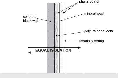
Figure 3.15:
Non-directionality of airborne sound isolation. Despite the asymmetric distribution of the isolation materials, the isolation for airborne sounds will be equal in either direction.
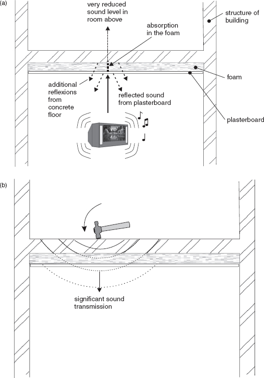
Figure 3.16:
Airborne and impact noise isolation: (a) For airborne sound; (b) for impact noises. Direct impacts on the structure can set the whole thing in motion, including anything that may be attached to it. What is more, a very wide range of frequencies are produced by the impact, which are capable of exciting many resonances.
The problem arises when people, and especially when wearing high, slim heeled shoes, walk on the upper floor. In this case, the weight on a small area when the heel strikes the floor presents a totally different case than if somebody were to strike the lower plasterboard ceiling with a similar shoe heel. The difference between this situation, where the isolation is not reciprocal, and the case of airborne noise isolation, where reciprocity exists, lies in the nature of the impedance differences.
When a shoe heel strikes the hard surface of the upper floor, the heel is brought to rest almost instantly. The transmission of the impact energy into the floor is great because the termination is abrupt and resistive (solid). If the heel were to strike the plasterboard surface, below, the surface presents a less abrupt termination to the impact. The plasterboard on the foam will tend to give, acting like a shock absorber, and the springiness will rebound and return some of the energy to the heel. There will be a sensation of a bounce-back; the termination will be more reactive (see Glossary). Such solid object-to-solid surface contacts are not typical of the gas/solid/gas contacts of normal airborne sound isolation, and they behave differently.
Without making a complete break in the solid materials it is very difficult to prevent the structural impact noises from penetrating most practical ceiling isolation systems. This is where the problem arises when structural ceilings are too low, and there is too little room to use a separate set of ceiling joists on the floated walls to float a completely separate ceiling structure. One solution to the problem is to use a simple floated floor system, such as that shown in Figure 3.4(d), on the floor above, but this may not be possible when the upper floors are occupied by different owners. In any case it may not be possible to float the floors because of the need to change doors and their frames if the raised floor reduces headroom below legal limits.
In general, adequate isolation may be difficult if not impossible to achieve when chosen premises do not have adequate ceiling height.
3.9 The Distance Option
The degree to which sound isolation is required in any proposed recording studio building is dependent upon several factors: the construction of the building (whether light or heavy); the proximity of noise sensitive neighbours; the proximity of external noise sources, and also the nature of the recording to be undertaken. All affect the noise control calculations. At one extreme, let us imagine a synthesizer-based musical group, who wanted to make recordings in a studio on the ground floor of a massively built farm building in a valley. If this building were sited miles away from any neighbours, and was not subject to any farm machinery or heavy transport noise, then the sum total of isolation needed would probably be to fit double-glazing with 40 cm between the panes of glass, and change the doors to a type with good acoustic isolation.
At the other extreme, let us consider the isolation needs for a recording studio for orchestral and choral use, sited in an office building in a location above an underground railway and surrounded by streets with heavy traffic. In this case, it would be unacceptably expensive for noise-induced delays to affect the recording of a 100-piece orchestra due to underground train rumble during quiet passages. It would also be unacceptable for the fortissimo passages to disturb people who may be concentrating on their work in adjacent offices. The isolation work may require the construction of an entirely floated inner isolation shell, of considerable weight, which may need reinforcement of the floor in order to support it. In turn, this new hermetically sealed box would need to be penetrated by HVAC (heating, ventilation and air-conditioning) systems, which themselves would require considerable isolation. The costs could be very high indeed.
In the first of the cases discussed above (the studio for the synthesiser band), probably the only acoustic recordings would be of close-mic’d vocals and the occasional guest musician. Neither the sound egress nor ingress would be particularly problematical, because there would be nobody to annoy by any external leakage of the sound, and except for the rare coincidences of extreme weather conditions during the recording of an even rarer acoustic guitar, the signal-to-noise ratio of recordings would generally be excellent. The only problem in this type of situation is that it would be restricted in its use. To some degree, though, all recording studios are restricted in their use; none are universal in their applications.
In the second case, after due isolation work and internal acoustic treatment, the studio would be capable of recording just about any type of music at any time of day. The main restriction would be financial. After spending so much money on the studio building and preparation, the hourly rate would need to be prohibitively high for the general overdubbing of vocals, for example. That high hourly rate may be inconsequential though, compared to the cost of an orchestra’s expenses when travelling to a studio in a distant out of town location.
It is true, therefore, that an isolated location, by virtue of its distance from noise related problems is an option for reducing isolation costs, because the physical, geographical isolation is acoustic isolation. However, when overall convenience of access is important, this geographical isolation may be completely impractical, so the only solution may lie in the choice of an inner-city site and a considerable amount of acoustic engineering.
3.10 Discussion and Analysis
Clearly, isolation is not a simple subject to grasp, and no simple computer programs can solve the problems. Isolation is a subject for specialists, and where critical situations exist, the cost of calling in a specialist before construction will surely be less than the cost of trying to fix the problems after construction. In fact, the problems may lie deep within the construction, in which case total rebuilding may be required. Intuitively, leaving out a layer of fibrous material between two of many layers in an isolation system may seem insignificant, but if the cavity resonates without the lining, the air at resonance can be a remarkably strong coupling medium.
The addition, or not, of a small component in a complex structure may thus make a disproportionate difference to the results, and even one decibel of improved isolation may be important. Experience has shown that it is better to design for inaudibility for the neighbours, rather than to legal limits, because peace with the neighbours can be crucial to their tolerance of the occasional nuisance. Nevertheless, ultimately the law will decide if the worse comes to the worst, and that is where that 1 dB can mean make or break.
In fact, if the room shown in Figure 1.1 had failed to achieve its low frequency isolation target by 1 dB, then where would one begin to look for the weakness? What would one do to plug the 1 dB leak? If the room had been completed, with all its decorations, and was considered by all concerned to sound good, then how could an extra decibel of isolation be found without perhaps destroying all the finishes, changing the sound within the room, and severely straining the finances of the owners? These are not easy questions to answer; not even for experts, so to fail by 1 dB could be disastrous.
Efficient acoustic engineering implies that the maximum effect is achieved with the minimum use of resources, but isolation in difficult situations does not always lend itself to precise analysis and the presentation of finely tuned solutions. Despite the fact that isolation can be expensive, there needs to be a safety margin in the calculations and assessments of situations, because the science is not exact and the cost of failure can be so grave. It is always better to err on the safe side. The subject of the rather imprecise nature of isolation measurements is discussed in more detail in Section 10.7.1.
Isolation work is something that should not be undertaken without adequate knowledge of the subject, because much of it is very counter-intuitive, and the potential for disappointing results and wasted money are very great.
3.10.1 Fibrous and Cellular Springs – Thicknesses and Densities
To highlight some of the above points, and to answer the queries of some readers of the first edition of this book, it may be informative to discuss the seemingly simple subject of the resilient layers below floated floors. However, despite the fact that it may seemingly be simple, there are many factors which need to be taken into account in order to choose the most appropriate density and thickness for any given application.
As shown in Figure 3.5, if the elasticity of the floor floating springs is either too great or too little, good isolation will not be achieved. Below the resonant frequency of the mass/spring system, such as that formed by a floated concrete slab and a mineral wool layer beneath it, most of the isolation is lost. At and around the resonant frequency, the isolation can actually be worse than with no treatment at all, because of the amplifying effect of the resonance. In general, isolation is considered to begin to become effective above about 1.4 (√2) times the resonant frequency; thus if isolation down to 20 Hz is required, the floor resonance should be below about 14 Hz (14 Hz × 1.4 = 19.6 Hz). Nevertheless, effective isolation does not tend to occur until the resonant frequency is around half the lowest frequency to be isolated. In practice, for full frequency range isolation, 12 Hz is a good target to aim for.
Using a weaker spring will lower the resonant frequency, as will increasing the weight placed upon it, but as shown in Figures 3.6 and 3.7, if the spring material is too weak then floor stability and flatness may be lost. If, for example, 70 kg/m3 mineral wool were to be used as the base, then doubling the density to 140 kg/m3 would increase the resonant frequency (by virtue of providing a stiffer spring) by √2 (1.414). Halving the density to 35 kg/m3 would reduce the resonant frequency by the same amount. If the higher density was necessary in order to give increased stability, then the only way to reduce the resonance frequency to its original value would be to double the weight resting upon it.
If the resonance frequency were required to be halved, whilst using the same mineral wool spring (or, in fact, any given spring), then the weight would need to be quadrupled. That is, if the frequency of resonance of a 10 cm concrete slab floor resting on a given mineral wool base spring were to be halved, then 40 cm of the same concrete would be necessary. Adjusting the springs is therefore often a more practical (and height saving) option than adjusting the masses. Of course, one could always increase the density of the concrete if the height increase from 10 cm to 40 cm was unacceptable, but even a density change from 2 tonnes per cubic metre to 3 tonnes per cubic metre would still need a thickness of about 27 cm.
Note, here, that the weight (mass×gravity) is what is important. This gives rise to the force acting down upon the spring. In the case of the mineral wool, the density affects the elasticity of the spring, whereas the concrete density affects the weight (and hence force) applied to the spring for any given thickness of slab.
However, as we shall see below, we cannot reduce the mineral wool density too far or it may become so compressed that it loses its elasticity and ceases to behave like the required spring. Furthermore, if the mineral wool is compressed to a thickness commensurate with any irregularities in the surface of the floor on which it is laid (or the concrete that may be poured on top of it), then at some places rigid contacts may be made as some points penetrate the material. This problem can be ameliorated by placing a layer of plywood, for example, on top of the mineral wool, and smoothing the floor below it, but such treatments tend to be wasteful of time and materials compared to simply using a thicker layer of mineral wool and/or a higher density.
3.10.2 The General Situation with Masses and Springs
Figure 3.17 shows a graph of the relationship between the mass and the resonance frequency when the mass is loaded on a moulded panel material made from glass fibre, sold under the trade name of Acustilastic. The aforementioned 12 Hz resonance can be seen to be achieved with a load of about 230 kg/m2, which would signify a 10 cm slab of 2.30 density concrete (2.3 tonnes per cubic metre). Another type of graph which is commonly encountered is shown in Figure 3.18. In this case, it is for a granular, rubber-based matting used typically under brick or concrete block walls, where the loads can be very great. The graph shows the degree of compression under load – up to 300 tonnes per square metre. Although this does not directly show the resulting resonant frequency, it can be calculated from applied force (the weight) and the degree to which the material is compressed under static load as a proportion of its original thickness (see Subsection 3.10.4). In both cases (Figures 3.17 and 3.18), it can be seen that the relationships are described by curves, and not by straight lines, because as the materials are compressed their densities increase. Consequently, a 70 kg/m3 mineral wool base compressed to 50% of its original thickness would then have a density of 140 kg/m3, and so would resist a given extra force (weight placed upon it) more than would the uncompressed mineral wool. In other words, if a 50 kg weight over a given area compressed the original 70 kg/m3 mineral wool by 4 mm, the addition of an extra 50 kg/m2 would only compress the material by around a further 2 mm.
In the case of Figure 3.17, the graph stops at 2250 kg/m2. This material (Acustilastic) has an allowed maximum deformation of 30% (which corresponds to a resonant frequency of 4 Hz with the 2250 kg/m2 load) because above around 2500 kg/m2 the material goes beyond its elastic limits and begins to permanently deform due to the breaking of individual fibres. The recommended usable load for this material is 2000 kg/m2. However, if significantly heavy loads are expected to be placed on such a floor, the usable load would need to include the extra load, and cannot be consumed by the floated slab alone. The resonant frequency would be a function of the total load. In the case shown in Figure 3.7, where the walls and ceilings are also loaded on the slab, their extra weight will also contribute to the overall load and so they must also be taken into account when calculating the final resonant frequency of the floor when the whole room is finished and loaded with equipment.

Figure 3.17:
Load versus resonance frequency graph for the material Acustilastic. It can be seen that the weight of the load must be quadrupled in order to halve the resonance frequency; hence to quarter the resonance frequency the load must be multiplied by sixteen.
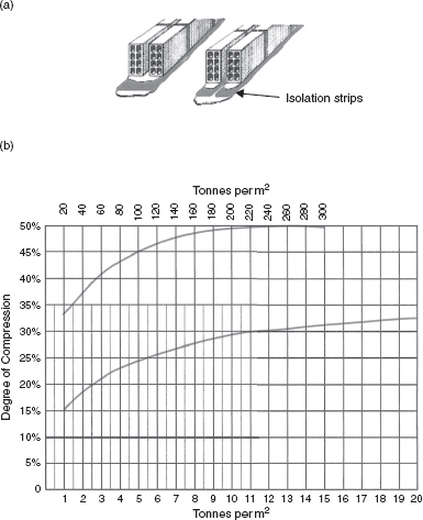
Figure 3.18:
(a) Typical application of the material for floating heavy walls; (b) Plots showing the degree of compression of the material with different loads.
On the subject of the thickness of a ‘spring’ material, consider the examples shown in Figures 3.19, 20 and 21. In Figure 3.19, a single spring is loaded by a given weight and can be seen to compress by 20% of its original length. In Figure 3.20, two similar springs are placed in parallel and loaded by the same weight, where the deflexion can be seen to be less for each spring. In Figure 3.21, however, the two springs are placed one on top of the other – in series – and as the force acting upon them is equal (i.e. they are each carrying the same load – it is not divided between them) they each compress to the same degree as the single spring shown in Figure 3.19. The proportional compression of each spring would therefore be the same as for the single spring.
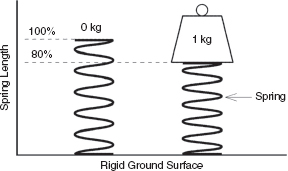
Figure 3.19:
In the example shown, a weight of 1kg has compressed the spring to 80% of its unloaded length.

Figure 3.20:
In the case of the two parallel springs, each identical to the single spring shown in Figure 3.19, the compression for each spring is half of the compression of the single spring: the force on each spring is half of the force on the spring shown in the previous figure. The resonance frequency will rise by √2 (1.414) compared to the resonance frequency shown in Figure 3.19 because the stiffness has been increased.
Nevertheless, twice the total deflexion would be experienced, so effectively the spring would be softer. The stiffness would be halved, so the resonant frequency of the mass/spring system would be the resonance of the same weight on a single spring divided by √2, i.e. 1.414. (The same work cannot compress two springs as many times per second as it can compress only one spring.)

Figure 3.21:
In the above example, two springs, each identical to the spring shown in Figure 3.19, are placed in series. The force acting on each spring is the same, and is also the same as the force acting on the spring in Figure 3.19, so the compression of each spring will also be the same. However, the overall effect is that of a softer spring, as the total compression distance is double that of a single spring and the resonant frequency will be that of Figure 3.19 divided by √2 (1.414).
Consequently, doubling the thickness of a mineral wool base below a concrete slab would reduce the resonant frequency by a factor of about 1.4. Halving the thickness would increase the resonant frequency by about 1.4. Doubling the density or halving the density of the mineral wool would also increase or reduce the resonant frequency by a factor of about 1.4, respectively. However, as previously mentioned, if the initial thickness of the material is too little, and/or the density is too low, the material may be compressed to the extent shown in Figure 3.5(c), in which case the spring effect may be lost, and with it much of the isolation if it were the base for a floated floor.
Figure 3.22 shows a somewhat more complicated case. Here, two springs of different stiffness are placed in series, one on top of the other. Despite being in series physically, their stiffnesses behave like two electrical resistors in parallel – the resultant stiffness is always less than the least stiff spring, just as the combined resistance of two parallel resistors is always less than the lower of the two resistances. For resistors in parallel, the combined resistance is calculated by dividing the product by the sum; in other words:
![]()
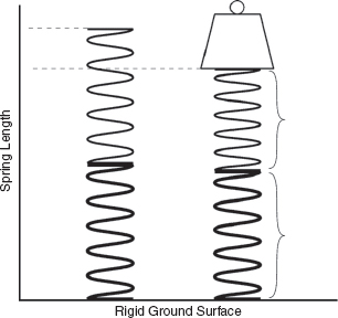
Figure 3.22:
In this example, two dissimilar springs have been placed in series. The result is still a single resonance frequency, because the springs combine to yield a total stiffness which can be calculated from the product divided by the sum, as for parallel resistors or inductors, or capacitors in series.
For two parallel resistors of 10 ohms and 20 ohms:
![]()
(In fact, the springs in series behave like two capacitors in series, but the concept of resistors is perhaps more widely understood by people not so conversant with electrical theory.)
The resonance frequency of the system shown in Figure 3.22 with respect to that shown in Figure 3.19 can be calculated from the change in stiffness, but it will always be below the resonance frequency of either of the single springs loaded with the same weight. However, if we separate the springs by another mass, as may occur if a floated floor is laid on top of an already resonant floor – which has its own mass and spring components – the situation begins to become rather complicated. The concept is shown diagrammatically in Figure 3.23. If the two resonant systems share the same resonant frequency, individually, then the interactive coupling will move the resonances apart. Prediction of exactly what will happen in practical structures is very complicated, as many of the relevant parameters will not be known.
On the other hand, if the resonances of the two systems are well separated, then one resonance may dominate, or the pair may behave chaotically, especially under transient excitation. Parallels can be drawn with the behaviour of double pendulums and their ‘strange attractors’ described in chaos theory. In the automobile industry, such complicated multiple spring/mass systems are sometimes used, where the huge research and development costs of modelling and measuring can be amortised over a long production run of identical vehicles. Conversely, most acoustic calculations for architectural sound isolation purposes relate to one specific job, so it is usually better to stick to the use of more easily predictable systems, and to avoid double mass/spring systems because the research costs usually cannot be supported.

Figure 3.23:
This can be a difficult problem to calculate, because in practice, combined structures are rarely pure springs or pure masses. The springs in this example are separated by a mass, so two resonant systems exist. There are two degrees of freedom, and interactions of accelerations. Had the two springs and masses in the above case been equal, they would still not resonate at the same frequency because the resonance would be displaced by the interactions.
In multiple mass/spring systems, factors such as the relative masses or stiffnesses will also have to be taken into consideration, as will any damping or loading effects which one system may impose on the other. What is more, if the masses are reasonably similar to each other they may interact in a way which is very different to the case if they were greatly different. The importance of the various rules which govern the behaviour of such systems can therefore change with the relative proportions of each system.
As a practical example of this type of double system, one can imagine a case where a floated isolation floor needs to be laid over a structural floor at ground level, but with a subterranean car park below. It is not uncommon to find such floors with natural resonances in the region of 20 or 30 Hz. In general, if a load-bearing, structural floor exhibits a relatively high resonance frequency, then a floated floor of soft springs and high mass (low stiffness, high inertia) may be needed in order to achieve much isolation below the resonant frequency of the structural floor. If that floor cannot support such a load, then achieving useful low frequency isolation may be out of the question. These are the sorts of situations where the experience of acoustics engineers is invaluable on a case-by-case basis. There tend to be too many variables in this type of equation to expect a simple computer analysis to predict the results.
In practice therefore, combinations of slab thickness and density both affect the weight (mass), and changes of the thickness and density of the mineral wool will affect the stiffness of the spring. All of these changes will have effects on the resonance frequencies of the systems. When considerations such as floor height or strength must be taken into account the parameters will be chosen for the most practical result. For example, a mineral wool under-layer which is doubled in thickness and halved in density will lower the resonance frequency by half; achieving a reduction of √2 from the doubling of the thickness and a further √2 from the doubling of the density. The resonance could be returned to its original frequency by quartering the weight of the concrete slab. Such a change may be necessary if a lighter weight or less high floor was required, but the floor would also, obviously, be much weaker with only one quarter of the thickness of concrete. On the other hand, rigidity could perhaps be increased by choosing a thicker layer of a lower density concrete and using more steel reinforcement mesh. Such are the decisions of an acoustics engineer.
3.10.3 Measured Characteristics of Various Suspension Materials
In order to show the effects of the practical application of a selection of commonly used materials for floating floors, a series of measurements was undertaken specifically for the second edition of this book. Materials were cut into samples of 10 cm squares (i.e. 100 cm2). On each sample, a 1 kg weight would equate to approximately 100 kg/m3, allowing for small differences due to the different ratios of surface area to edge. The material samples were placed in a device which allowed different weights to be loaded onto them, and to be distributed evenly over their surfaces by means of a light but rigid plate of the same size as the samples. In each case, the height of each material sample was measured unloaded, then measured again at increments of 1 kg between 1 kg and 10 kg, the latter corresponding to approximately 1 tonne per square metre.
Figure 3.24 shows the static loading effect on two samples of a reconstituted polyurethane, open-cell foam, known as Arkobel, having a density of 60 kg/m3. In three of the measurements the sample is the same, but it has been rotated in each case through 90 to measure each axis separately. There is one axis of recommended use, preferred because of the direction in which the foam is cut after compression during the manufacturing process. The preferred axis can be seen to exhibit a curve which is a little less steep overall. However, what is interesting is that when the sample was unloaded, from 10 kg back to 0 kg, the curve did not follow the compression curve. The material was exhibiting hysteresis (see Glossary) under static conditions, but this should not introduce any unwanted effects under dynamic conditions because the vibrational movements would be much too small to exhibit non-linearities.
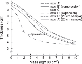
Figure 3.24:
Compression versus load for 10 cm and 20 cm Arkobel (a reconstituted polyurethane foam) of 60 kg/m3 density. The thicknesses of the 20 cm samples have been divided by two on the plots in order to make easier comparisons with the 10 cm samples. In fact, the 20 cm sample compressed in ‘axis A’ coincides so well with the 10 cm sample in the same axis that the two lines are almost indistinguishable. Axis B is the normal axis of use. The hysteresis loop shows the different behaviour in compression and expansion.
A 20 cm sample was then tested in the ‘A’ and ‘B’ axes, with the figure showing the results divided by two, which overlays the 10 cm and 20 cm curves for easy comparison. In the ‘A’ axis, except for the section between 0 kg and 1 kg, the plots overlap exactly, showing the practical results of the effect shown in Figure 3.21 relating to springs in series. The ‘B’ axis of the material, in both the 10 cm and 20 cm samples, exhibits a slightly less regular curve, but the agreement at low and high loadings is relatively consistent.
Figure 3.25 shows the plots for a type of Arkobel with double the density of the first sample – 120 kg/m3. Samples of 6, 9 and 18 cm were tested. Normally, this higher density is used in smaller thicknesses, such as 3 cm, but for these tests the deflexions would be too small for reliable measurement, so greater thicknesses were chosen. The 18 cm sample measurements have been divided by two for easier comparison of the plots. It can be seen that the proportional compression is much less than for the 60 kg/m3 sample. Nine point seven centimetres of 60 kg Arkobel compresses to about 3.7 cm under a 10 kg load, whereas 9.1 cm of 120 kg Arkobel compresses to only 6.9 cm under a similar load – a deflexion of 2.2 cm as opposed to 6 cm.
An interesting observation from Figure 3.25 is the comparison of the multiplication of the 6 cm sample measurement by 1.5, overlaid on the 9 cm sample plot. At loadings above 8 kg, the 6 cm sample curve begins to flatten out, showing that the thinner sample is beginning to bottom; that is, compress beyond its elastic limits. This effect is also observable with the thinner samples in Figures 3.26 and 3.27. The bottoming occurs when the material begins to be compressed into a solid mass, and the mechanisms which give rise to the springiness begin to cease to operate. (See Figure 3.5 (c)).

Figure 3.25:
Compression versus load for different thicknesses of Arkobel (reconstituted polyurethane foam) of 120 kg/m3 density. The 6 cm measurement multiplied by 1.5 is overlaid on the measurement for the 9 cm sample. The two plots correspond very closely up to 8 kg, after which the 6 cm sample begins to compress less, indicating that it is beginning to ‘bottom-out’. The 18 cm sample (÷ 2) and the 9 cm sample show no such effect.
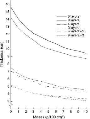
Figure 3.26:
Compression versus load behaviour of various thicknesses of Blancot, a cotton-waste felt material of around 60 kg/m3 density. The 3 layer plot and the 9 layer plot ÷ 3 are identical up to 4 kg loading, after which the 3 layer plot shows evidence of bottoming out as the thinner sample begins to compress proportionately much less than the thicker, 9 layer sample.
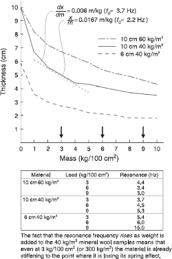
Figure 3.27:
Compression versus load for different thicknesses of 40 kg/m3 and 60 kg/m3 mineral wool. Again, bottoming-out is evident above 8 kg/100 cm2 loading for the thinner sample of the lower density material. The resonance calculations relate to the descriptions given in Subsection 3.10.4. Of the two samples which had a thickness of 10 cm when unloaded, the lower density material, as expected, compresses much more as weight is added, up to about 4 kg/100 cm2, but thereafter compresses less than the higher density sample. This suggests the beginning of a bottoming-out process for the lower density sample under higher loads. In the resonance/load table, note how the resonance frequency begins to rise abruptly once the bottoming-out begins, showing that the spring is becoming very stiff.
The Blancot (a cotton-waste felt material) shown in Figure 3.26 exhibits a different shape of curve to the foam materials in the two previous figures. In this case, the 9 layer measurement divided by 3 and overlaid on the 3 layer measurement shows that the 3 layers begin to bottom at loads above 4 kg (400 kg/m2), and between 8 and 10 kg there is a horizontal straight line, showing that the material has ceased to act as a spring. The density of this Blancot is the same as that of the first Arkobel sample, 60 kg/m3, but a comparison of Figures 3.24 and 3.26 shows that the way in which the two materials compress is very different, as shown by the different curve shapes, particularly in the lower half of the weight scale.
The mineral wool plots shown in Figure 3.27 are different from both the Blancot and the Arkobel. Of the lower density samples, the plots show a high initial rate of compression which rapidly begins to flatten out, and indeed bottoms out in the case of the thinner sample. The 10 cm sample of the higher density (60 – 70 kg) is very typical of what is often used in studio isolation floors. Finally, Figure 3.28 shows an interesting comparison of the different slopes and shapes of the different materials as measured for the previous figures. Clearly, there are some very different mechanisms at work which are giving rise to their elasticity. They are most certainly not perfect, theoretical springs.
3.10.4 Calculation of Resonance Frequency
From the measured deflexions of the materials, the resonance frequency for each mass/spring combination can be calculated. If the spring is perfect, i.e. 2 × load = 2 × deflexion, the resonance frequency is given by:
![]()
where x is the deflexion in metres and g is the acceleration due to gravity (9.81 m/s). In general, as shown above, practical materials do not behave as perfect springs and the stiffness of the spring changes with changing load. Under these conditions, the resonance frequency for a particular load may be estimated from the slope of the load/deflexion curve, thus:
![]()
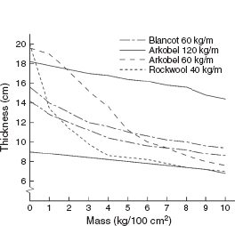
Figure 3.28:
Comparison of the shapes of the compression versus load curves for the different fibrous and cellular materials. The cellular materials can be seen to behave more uniformly, which is evident from the straighter nature of the curves. Clearly, the mechanisms giving rise to the spring-like behaviour are different in each material.
where dx/dm is the slope (gradient) of the load/deflexion curve at the applied mass m (note that for a perfect spring, dx/dm = x/m and the two expressions become identical).
By way of example, marked on Figure 3.27 are two estimates of the resonance frequency of a material (which is clearly not a perfect spring) loaded with a mass of 2 kg/100 cm2, one based on the static deflexion and the other on the slope of the curve. The static deflexion estimate is shown to be less than half the value of the more reliable estimate based on the slope of the curve, and the predicted resonant frequency is considerably higher.
3.11 Summary
When anything is immersed in a sound field it will, to some degree or other, be set into vibration. Any vibrating structure can, depending upon the degree of isolation that it can achieve, receive the vibrations on one of its surfaces and re-radiate them from another.
When a sound wave strikes any surface, the three possibilities are that the energy in the wave can be reflected, transmitted, or absorbed.
Absorption can be achieved in several ways, such as by tortuosity, particulate friction and internal viscous losses.
Porous absorbers work best in situations of maximum particle velocity, such as at pressure nodes and at high frequencies.
The differences in the speed of sound through the different materials in the structure of a building can give rise to great difficulties in predicting the structural vibration and re-radiation.
Isolation is best achieved by reflexion, because isolation by absorption would generally be too bulky to be practical.
The three basic means of sound isolation are mass, rigidity and distance; but acoustic damping can also play a prominent part.
The use of springs to isolate internal and external structures is usually the best way to achieve high isolation; by decoupling.
A good hint to remember is that springs do not like to change their length, and masses do not like to change their velocity. When something tries to vibrate a mass/spring system, both the mass and the spring try to resist the vibration, for their own individual reasons. Working together, they can make very efficient isolation systems.
The degree of isolation needed at any given frequency will be dependent upon circumstances and the type of recordings to be made. Low frequencies are generally much more difficult to isolate than high frequencies, though the general reduced sensitivity of the human ear to low frequencies at low levels helps to mitigate the problems incurred.
For floated isolation systems to be effective, their frequency of resonance must be below the lowest frequency to be isolated.
In weak buildings, adhesive mounted isolation systems can be attached to all parts of the internal surfaces.
Complex isolation structures are difficult to analyse, and a degree of empirical experience is often needed to achieve reliable predictions of the outcome of a design.
Impact noises can be much more difficult to deal with than airborne noises.
If possible, careful choice of location can also be instrumental in reducing isolation requirements.
Mass/spring systems are often used for making isolation floors by means of concrete slabs over mineral wool bases.
Doubling or halving the mass, whilst maintaining the same spring, will respectively lower or raise the resonant frequency of the system by √2. Quadrupling or quartering the mass will respectively halve or double the resonance frequency.
Doubling or halving the stiffness of the spring, such as by means of doubling or halving the density of mineral wool (the initial thickness remaining the same), will respectively raise or lower the resonance frequency of the system by √2. Quadrupling or quartering the stiffness will double or halve the resonance frequency.
Doubling or halving the thickness of a mineral wool spring will lower or raise the resonance frequency by √2. Quadrupling or quartering the thickness will respectively halve or double the resonance frequency.
Mass/spring, floated floors begin to become usefully effective in their isolation about one octave above their resonant frequency.
Resonant frequencies can be calculated from the applied force (mass × gravity, or weight) and the proportional compression of the spring.
Two identical springs in series (such as doubling the thickness of a mineral wool base) will reduce the resonance frequency by √2.
Two identical springs in parallel (such as achieved by doubling the density of a mineral wool base) will increase the resonance frequency by √2.
Springs of different stiffness, placed in series, will behave like electrical resistors in parallel, and the combined stiffness will always be below the stiffness of the weaker spring.
Systems with two degrees of freedom, such as mass/spring/mass/spring, can behave in complex ways. If the two masses and springs are identical, the resonances will not be: they will move apart. If the masses and springs are not identical, then their behaviour can depend on their relative proportions. Prediction of the overall behaviour can be very difficult to achieve: one resonance may dominate, or the two resonant systems may even behave somewhat chaotically under shock excitation.
Reference
1 Fahy, Frank, Foundations of Engineering Acoustics, Academic Press, London and San Diego, p. 331 (2001)
Bibliography
Gréhant, Bernard, Acoustics in Buildings, Thomas Telford Publishing, London, UK (1996). Originally published as Acoustique en Bâtiment, Lavoisier Tec & Doc, Paris, France (1994)
Parkin, P. H., Humphreys, H. R. and Cowell, J. R., Acoustics, Noise and Buildings, 4th Edn, Faber and Faber, London, UK (1979)