
CHAPTER 26
Analogue Audio Interfacing
General interfacing problems. Old solutions. Modern developments. Polarity standards. The case for jackfields. Balanced–unbalanced interfacing. Grounding of signal screens.
When people plan their first studios of any significant complexity, they are often shocked once they find the true cost of the cables and connectors needed to interface all the equipment. They tend to count carefully the cost of the items of equipment when preparing their budgets, but when everything is ready for installation, and the reality of the interconnection costs confronts them, there is often not sufficient money left to do the equipment justice. It is always a great risk to cut corners on the audio cabling infrastructure because so many seemingly simple solutions can lead to traps. A simple lead, such as one connecting a phono (RCA) plug to stereo jack plug, may seem appropriate to connect the output of one device to the input of another, but there could be five or six ways of connecting those two ‘simple’ plugs. Although under many circumstances a signal will flow between the two pieces of equipment with any of the likely wiring arrangements, it is surprising to many people just how wrong some of those connections can be, and how they can degrade the sound without necessarily making any change in the measured frequency response.
Figure 26.1 shows a range of possible methods of connecting the two connectors mentioned above. In many cases, these get made in studios for specific purposes, but subsequently they get used for other purposes for which they ‘look right’, but are unsuitably connected. A typical example would be a cable which was perhaps being used to connect the unbalanced output from a CD player into the balanced tape return input of a mixing console, but which had originally been made to connect the transformer balanced output of compressor into an unbalanced input of a tape recorder. (The input and output function of each connector thus being reversed.) Whether or not it works in its new role is entirely dependent upon the type of balancing used in the input circuitry. The result of such a random interconnection may be noisy, it may be quiet, it may sound ‘perfect’ or it may sound degraded. The result of the incorrect wiring may be totally impossible to predict without knowledge of the precise type of circuitry to which it is connected, and which will not be described in most manuals for semi-professional equipment. The individual pieces of recording equipment in any studio really need to be brought to a common place of standardised termination if they are to be flexibly and reliably connected together. The normal analogue way of doing this is via a 3-pole jackfield (or patchbay in US English).
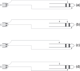
Figure 26.1:
Viable RCA (phono) to 3-pole jack configurations. Four possible wiring arrangements which are likely to be found in studios. (d) is an arrangement which may be found when using some mixing console insert jacks as ‘direct’ sends, or, in some cases, returns. All of the above have their specific uses.
We currently have a state of affairs whereby equipment manufacturers produce their equipment, often with little regard for how compatible it will be in its interconnection with other equipment. This is a more or less inevitable consequence of the evolution of much ‘semi-professional’ equipment out of the consumer market, where no interconnection standards were ever properly developed. In the realms of truly professional equipment there is less of a problem, because the professional equipment evolution has been more controlled.
26.1 The Origins of the Professional Interfaces
In the early days of recording, valve (tube) equipment demanded a strict code of interface. Valves could not easily drive long lines directly, so transformer matching was used. The lines were usually run at +4 dBm (0 VU) which was 1.223 volts into a 600 ohm load, a standard which had been adopted by telephone companies as the best compromise between noise and crosstalk in telephone systems. The jackfields themselves were also borrowed from telephone technology, where they were used in the switchboards of exchanges. Output transformers required accurate terminations if their frequency responses were not to be disturbed, so inputs were terminated with standard 600 ohm impedances. Partly to ease the loading problem of one output feeding multiple inputs (which was a more usual requirement in studios than in telephone systems), the studio industry began to terminate the outputs directly, and not rely upon a 600 ohm loading by the following input. This allowed 10 kohm ‘bridging’ input impedances to be used, and by the mid-1960s almost all professional studio equipment had nominally 600 ohm outputs and 10 kohm inputs; balanced, of course. Forty years later, at the top of the professional end, electronic balancing of inputs has become widespread, and the outputs have often tended to become unbalanced, although they are almost universally of very low output impedance; less than 50 ohms. However, there is usually no problem whatsoever in interconnecting any of the truly professional equipment produced over the last 50 or 60 years. Old style outputs will drive old or new style inputs, with at worst only the addition of a simple resistor, and old style inputs will accept new or old style outputs. About the only complication that arises is that it may still be necessary to confirm which pin is in-phase ([ + ] [hot] [live]) on an XLR type connector.
The Cannon XL connector (‘L’ for the ‘latching’ version of the original ‘X’ connector) was widely used in the 1950s as a professional audio connector, but it was found that there could be problems of poor contacts after many insertions. Cannon’s fix was to use a resilient rubbery material in which to mount the contacts, so that they could be slightly offset and made to wipe on each insertion or withdrawal. The resilient (R) XL became the XLR connector, and it soon became, along with its equivalents by other manufacturers, very much a professional recording industry standard connector. In the United States, in the 1950s and 1960s, pin 3 usually seemed to be the accepted hot pin, with pin 2 being cold and pin 1 ground (earth). In Europe, pins 2 and 3 were frequently used in the reverse sense. In most cases, the male connector was used for outputs, but in the late 1960s, some recording equipment appeared with male input connectors and female output connectors, probably adhering to the concept that for safety (especially at higher voltages) outputs should not appear on exposed pins. Fortunately, this third ‘standard’ was rapidly abandoned, certainly for low level signals. Microphones have nearly all adhered to one standard pin configuration, with pin 2 producing a positive voltage in response to a positive pressure at the front of the diaphragm.
The AES (Audio Engineering Society) recommended standard is now for pin 2 hot, which would keep the microphone polarity-standard throughout the audio chain, but its adoption has not been universal. For some large manufacturers, with so many years of production behind them and so much equipment in the marketplace, to reconfigure their ‘in-house’ standard could lead to great confusion in the interchange of old and new equipment. JBL has suffered from this problem with their loudspeaker drive units, on which a positive voltage to the red terminal will produce a backwards (inwards) movement of the cone or diaphragm. The AES standard calls for a positive voltage on the red terminal to produce a positive pressure at the front of the cone; that is, an outward movement. JBL adhered to a very old but very logical standard. This stated that when the microphone diaphragm goes in, the loudspeaker cone should go out, because if the sound source was a voice, for example, it would be an out-going pressure from the mouth which would push the microphone diaphragm inwards, so the loudspeaker should follow the polarity of the source; not the microphone. However, few other companies followed this concept, but JBL produced such a large quantity of material that to change polarity after so many decades would be extremely difficult. There would be no way to inform all their users of the change, so old units would often be likely to be replaced by incompatible new ones, and total chaos could result, perhaps giving JBL products a bad name solely from the lack of information available to the people making the repairs. JBL compromised on this problem by making their newer cabinets adhere to the standard, so a positive voltage on the red terminal of the box will produce a positive pressure at the front of the loudspeaker, but the older style drive units remain as they were.
As previously stated, at least as all reputable microphones use pin 2 as positive (hot) there are usually no polarity problems in that department, except via incorrectly wired leads. In the case of a piece of equipment which is likely to be connected in different parts of the signal chain at different times, such as a tape recorder or an equaliser, then if it has balanced inputs and outputs, and if it is feeding and being fed from correctly connected balanced inputs and outputs, it really does not matter which pin is hot. As long as the inputs and outputs are in-phase with each other, the relative polarity of the signal will be maintained. The problems arise when a piece of equipment has XLR connectors on its main inputs and outputs, but jacks or some other similar connectors on intermediate inputs and outputs, such as insert points or compressor side-chains. In such cases, the polarity of the inputs or outputs on the jacks will be dependent upon whether pin 2 or pin 3 was ‘hot’ on the XLRs. Operators of mixing consoles need to know the phase relationship between external inputs and outputs and the jackfield, and this usually requires permanent and correctly polarised wiring of the equipment, which usually means that all inputs and outputs are brought to a standardised jackfield.
(Strictly speaking, the term ‘polarity’ should have been used throughout this discussion, and not phase, because a polarity reversal is a 180° phase change at all frequencies. However, the polarity reversal switches on almost all mixing consoles are labelled ‘phase’, and this terminological misuse has somewhat established itself, at least in many parts of the industry. Nevertheless, two signals with a relative phase shift of around 15° could be referred to as being substantially in-phase, but not in polarity. Polarity relates to phase relationships of 0° and 180° being ‘in’ and ‘out’ respectively.)
26.2 Jackfields (Patchbays)
It would seem to be a fundamental requirement of any studio which considered itself to be professional that the equipment should be wired to a central jackfield, and that this jackfield should be of a three conductor, tip, ring and sleeve type. In top line studios, this is de rigueur, but the home studio influence has cast some bad influences on many lower budget studios, and also on some others who should know better. The home studios and many project studios have often drawn their experiences, influences and equipment from various sources, including home hi-fi, consumer recording equipment, live (stage) equipment and the professional recording world. This can lead to a very difficult mixture of balanced and unbalanced inputs and outputs, from –20 dBV to +4 dBV nominal signal levels (low level outputs tend to be less costly to produce) and both two contact and three contact connections.
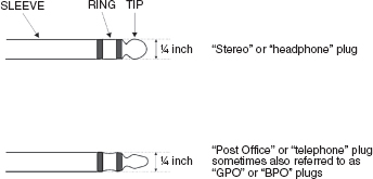
Figure 26.2:
Two types of ¼ in (6.35 mm) 3-pole jack plug. (Note: the ‘bantam’ or ‘TT’ jack plug is a 3/16 inch [4.76 mm] version of the GPO/BPO/telephone plug).
There are three basic types of 3-pole jacks, as shown in Figure 26.2. First there is the ‘stereo’ jack, where the plug is like a mono ¼ in (6.35 mm) jack with an additional ring connector. This type is used on many headphones. As long as the plugs and the connectors on the jacks are kept clean, they can perform well, and cost considerably less than the more professional types.
(Incidentally, in all cases, the ‘jack’ is the female connector, and the ‘jack plug’ is male.) For use in jackfields, quarter inch BPO jacks are preferable; these being again of a ¼ in (6.35 mm) sleeve diameter, but the ring and tip of the plug are narrower. They were formerly known as GPO jacks in the United Kingdom, and telephone jacks elsewhere, but the name changed when the General Post Office in the United Kingdom became the British Post Office. These are more expensive than the stereo jacks, but come with a variety of very hard, low resistance and self-cleaning contacts, with the normalling (switching) contacts usually being made from hard metals that will not oxidise, such as platinum or palladium and occasionally other related metals. These are fully professional jackfields, good for 20 years of daily use. Switchcraft, the US connector manufacturer, developed a miniature version of these jacks, variously called ‘bantam’ jacks or ‘TT’ jacks. TT stands for ‘tiny telephone’ and bantam is, according to the Concise Oxford Dictionary, ‘small but spirited’, for example bantamweight boxers. Due to their compact size and good performance, the bantam jacks are gradually taking over from the ¼ in (6.35 mm) types, though the smaller plugs can be tricky to wire unless special cable is used. Some of the varieties need special tools for assembly, and may perhaps not be able to be disassembled or reused. They are certainly nowhere near as robust as their ¼ in (6.35 mm) counterparts, which may ultimately be a better choice for smaller studio use as they are easier to wire, reusable, and, in most cases, less expensive, but the massive jackfields alongside many large studio consoles require the compactness of the bantams.
In general, and somewhat perversely, domestic/semi-professional equipment is often far more problematical to connect together than the very expensive professional equipment. In most cases, a relative novice at recording could successfully connect together the equipment of a fully professional studio, but it usually takes a real professional to wire together a domestic studio, once, that is, it progresses beyond a hard-wired package, and this is where a properly wired jackfield becomes invaluable. Be warned, though; except for the most basic of patching, mono jack, 2-pole jackfields are taboo. They create nightmares in terms of grounding (earthing) which usually can never be correctly resolved for all combinations of cross-patching.
26.2.1 Balanced to Unbalanced Problems
Three-pole jackfields should be wired with the ‘hot’ (+, in-phase) conductor of a balanced pair, or the signal wire of an unbalanced input or output, connected to the tip. The ‘cold’ (–, out of phase) conductor of a balanced pair, or the screen of an unbalanced cable, should be connected to the ring. The sleeve (ground) connector should only be used for the screens of balanced cables, and should never be connected to any conductor that forms part of an audio circuit, such as the screen of an unbalanced cable. There is a defective logic which is often applied which seems to imply that the difference between a balanced and unbalanced system is that there is no ‘neutral’, ‘cold’ connector on an unbalanced system. In fact, they both have a ‘hot’ connection, and they both have screens, but in an unbalanced system, the screen acts both as a ‘cold’ and a ‘screen’. One of the main drawbacks of this is that any interference which the screen shields from the ‘hot’ wire will cause a current to flow in the shared cold/screen conductor, so it will superimpose itself to some degree on to the audio circuitry. Correct and incorrect connection procedures are illustrated in Figure 26.3.
In a three-pole jack system therefore, wired as discussed, a balanced to balanced connection will pass through the jackfield as though passing down one continuous cable. An unbalanced to unbalanced connection will do likewise, though without any contact being made with the sleeve (ground) of the jack. A transformer-balanced output signal, appearing between the tip and the ring, will automatically connect correctly to the ‘hot’ and ‘cold’ connections of an unbalanced input without any change in the grounding arrangements. In the case of an unbalanced output feeding a balanced input, the situation is entirely dependent upon the type of balanced input being used. Here, there are three basic possibilities, as shown in Figure 26.4. The first is the old, reliable transformer balanced input. This is true balancing, with many megohms of resistance to ground. The drawback to using transformers are that they are very expensive (if they are to do justice to high quality sound equipment) and they usually cannot pass very low frequencies, although 5 Hz or less is possible with some better quality devices. (In many low budget studio though, the restricted low frequency response of the more moderately priced transformers is usually of lesser consequence, as the type of equipment chains normally found in such studios will also tend to have limited low frequency responses.) Secondly, and thirdly, there are two basic types of electronically balanced inputs, one of which can accept the ‘cold’ terminal being shorted to ground, and one which cannot. In the case of the type of balanced input which cannot accept its ‘cold’ being shorted to its chassis ground, care should be taken, and the manufacturer’s advice should be followed when connecting such an input to a jackfield. This point is a good example of how, in such situations, a jackfield can be used to standardise all inputs and outputs, so that with only a few exceptions anything can be connected to anything else, in any order. Grounding arrangements can also be optimised, so that hum and other noise pick-up is minimised, though contradicting requirements can exist. Nevertheless, if a few high quality transformers are accessible via the jackfield they can be brought into good use when otherwise incompatible interconnections need to be made.
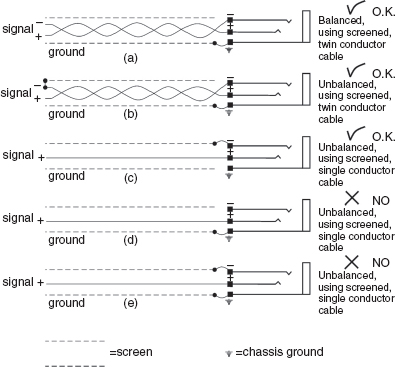
Figure 26.3:
Two and three wire connections to a jackfield.
26.3 Jacks – Two or Three-Pole?
An absolutely ludicrous state of affairs exists in terms of the use of the mixture of two-pole and three-pole jacks. It is frequently the case that much equipment using ¼ in (6.35 mm) jacks gives no information whatsoever as to whether the inputs and outputs are unbalanced or balanced, and whether or not they use 2-pole or 3-pole jacks. Even many instruction manuals give scant information about the terminations. Looking down into the jacks with the aid of a pen-light is one way to find out if it is definitely unbalanced, which it must be if there are only two contacts on the jack. On the other hand, some types of equipment use 3-pole jacks as standard, so even though a circuit appears to be balanced it may still be wired unbalanced. Even removing the top and bottom panels from the equipment may not readily reveal the answer, as double-sided boards are often employed and the jacks may cover the tracks. The difficulty of discerning the precise nature of the jacks inevitably leads many people to a ‘try it and see’ approach.
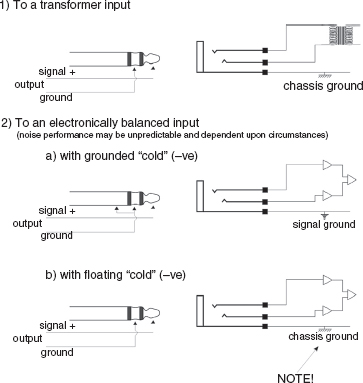
Figure 26.4:
Unbalanced outputs to balanced inputs.
In fact, there would appear to be no reason whatsoever, except for the excuse of saving an outrageously small amount of money, why 2-pole (‘mono’) jacks should ever be used on equipment intended for studio use, or even on musical instruments having line level connections and which are likely to be used in studios. However, this probably all goes back to the electric guitar and amplifier, with the historical standard use of mono jack plugs and high impedance leads. Early electronic keyboard instruments tended to follow the same standard, but the evolution of devices for use in conjunction with them conflicts badly with the professional studio wiring approaches. If only all new equipment used 3-pole jacks, wired in accordance with what was suggested earlier for jackfields, then it would almost all still be mono jack plug compatible, as the mono, 2-pole plug would always short the ring and sleeve together, hence, automatically remaking any separated contacts which needed connecting for unbalanced operation. Of course, this would preclude the use of certain types of electronic output balancing arrangements, though, (the ones which will not accept the cold [–ve] being connected to ground), but as these can often create more problems than they solve, their demise may be no great loss. However, such is still not the case.
26.4 Avoiding Chaos
It is true that for many smaller, low budget studios, jackfields, plus 40 or 50 patch-cords, are not cheap to buy, but nor would it be cheap to buy all the necessary permutations of other connectors and leads which would be necessary to be able to make the optimum interconnections between all likely combinations of analogue equipment patching. If errors were to be avoided when concentration was being applied elsewhere (such as on the musical aspects of the recording), then each piece of equipment would need to be clearly labelled with which configuration of cable it should be connected to. All two- and three-pole inputs and outputs would need to be clearly labelled. Furthermore, each lead would need to be clearly labelled at each end, explaining the pin connections, and a large stock of leads would be needed to allow for all likely combinations of equipment. The biggest problem would come in remembering the optimal grounding system to be used with each set up, and consequently whether the leads should be ones with the shields/screens connected at both ends, or just the input or the output end. In all cases, only balanced-type cable, with a good screen, should be used, and never guitar-lead type cable, with just a single core and screen, as there would be no way in this case of keeping the signal negative separate from the screen. (Incidentally, for non-native English speakers, the words ‘shield’ and ‘screen’ are totally synonymous in this use of the words, screen being the more common word in the UK and shield in the USA.)
Clearly, to do things properly with a discrete lead system is impractical, though the practice is widespread in many smaller studios. Furthermore, it would be unreasonable to expect even an experienced technical person to remember all the differing permutations, especially if work was rapid and/or pressurised. Nevertheless, many mixing console manufacturers produce 30 or 40-channel consoles entirely terminated by individual connectors on the rear panels. This is an unashamed marketing exercise, as they are producing consoles which in almost any serious operation need to be connected to an appropriate jackfield. Their argument is often that if the greater part of the customers for such consoles are too ignorant to realise what is truly necessary, and if the other console manufacturers are selling ‘stripped down’ versions, then they would be unable to compete (and hence to survive) if they produced more expensive products. They do have a valid point; but the real nonsense is that it probably costs the customers twice as much (at least) to fit an external jackfield than it would cost to fit one at the factory during production.
Ben Duncan, in his book High Performance Audio Power Amplifiers (Newnes, 1996, p. 331), referred to the following quotation, which is so apt for this situation. It was from John Ruskin (1819–1900): ‘There is hardly anything in the world that some man can’t make just a little worse and sell just a little cheaper, and the people who buy on price alone are this man’s lawful prey’.
26.5 Multiple Signal Path Considerations
What should also always be remembered is that a studio system is not just a big hi-fi system. A hi-fi system usually consists of a pair of signal channels, with the serial connection of no more than about three active devices. Typically, this would be a source (CD, tape, radio, etc.) a pre-amplifier and a power amplifier: there are usually no auxiliary sends and returns which are in simultaneous use with the main signal channels. There are therefore no parallel signal paths, except the left/right pair itself. Despite this apparent simplicity, many hi-fi enthusiasts go to great lengths to ensure the good quality of interconnect cables and plugs. It may seem strange to many people when they hear of hi-fi enthusiasts paying huge amounts of money for their inter-connect cables for their simple systems whilst many recording studios use only standard cable. Without doubt, there are some nonsenses involved in much of this cable mania, but there is at least one good engineering reason why hi-fi enthusiasts may be driven to pay vast amounts for interconnect cables is that much hi-fi equipment does not have output stages which can adequately drive the poorer quality cables. Top quality studio equipment tends to have output stages of much lower impedance and higher output capability, which are less prone to the limitations that can occur with much domestic hi-fi equipment. Good quality studio equipment is designed to drive long cables of standard quality, hence the ‘benefit’ from using esoteric hi-fi interconnects may not be relevant. Good quality standard cable will usually suffice. This is due to the fact that once we leave the realms of the seemingly simple serial signal paths, and enter the realms of multiple channels and parallel signal paths, a completely different approach needs to be taken to the system interfacing. A studio set-up is much more complicated than a domestic hi-fi system, and the opportunities for interference from mains-borne noise, radio frequency interference and interference induced from digital equipment are enormously greater. The wiring practices for hi-fi and studio systems are thus not necessarily directly applicable to each other. The circumstances of use and the characteristics of the equipment are often quite different.
26.6 Grounding of Signal Screens
Basically, for good interfacing, all equipment should use three-contact connectors, with the screen connection made nowhere else other than the chassis. Neve were doing this with their mixing consoles in the 1960s, and even then the practice was based on 20-year-old literature, so it seems that there are some slow learners around because so much equipment still does not respect this protocol. Neil Muncy outlined what he called ‘The pin 1 problem’ in a classic AES paper,1 in which he clearly threw down the gauntlet to manufacturers. In another paper in the same journal, Stephen Macatee very concisely reinforced the same point, and on some aspects of bad interfacing went even further.2 From that paper the following quotation has been taken:
The ‘pin 1 problem’
Many audio manufacturers, consciously or unconsciously, connect balanced shields (screens) to audio signal ground – pin 1 for three-pin (XLR-type) connectors; the sleeve on ¼ inch (6.35 mm) jacks. Any currents induced into the shield modulate the signal reference to that ground. Normally, great pains are taken by circuit designers to ensure ‘clean and quiet’ audio signal grounds. It is surprising that the practice of draining noisy shield currents to audio signal ground is so widespread. Amazingly enough, acceptable performance in some systems is achievable, further providing confidence for the manufacturers to continue this improper practice – unfortunately for the unwitting user. The hum and buzz problems inherent in the balanced system with signal grounded shields have given balanced equipment a bad reputation. This has created great confusion and apprehension among users, system designers as well as equipment designers.
Similar to the ‘pin 2 is hot’ issue, manufacturers have created the need for users to solve this design inconsistency. Until manufacturers provide a proper form of interconnect uniformity, users will have to continue their struggle for hum-free systems, incorporating previously unthinkable practices.
The ‘unthinkable’ practices to which Stephen Macatee refers no doubt include the ‘lifting’ or removal of safety grounds on equipment for which they are an essential part of the design. Experience has shown that there have been a greater number of studios which violate this legal and sensible requirement than those who completely comply with it. The problem is that with many equipment combinations, even of very well known manufacturers, there can simply be no other way to achieve a hum-free system. Well, it may be possible by fitting correctly configured input and output stages, or by adding separate transformers or line termination amplifiers, but this could double the cost of the installation. The reality is that, human nature and economics being what they are, if the cost is going to significantly increase then the ground comes off; dangerous or illegal as it may be. There is absolutely no doubt where the blame lies for this situation; it is rooted in the ignorance and marketing of equipment manufacturers, together with the users who demand ever-cheaper equipment.
26.7 Balanced versus Unbalanced – No Obvious Choice
Balanced systems have two inherent advantages over unbalanced systems: the ability to reject more noise and interference, and the ability to completely free the signals from a noisy ground. Unfortunately, good balancing arrangements tend to be expensive, and this does not fit in well with the cost-conscious philosophies of most of the more competitively priced recording studios. There are situations where nominally balanced inputs are not very well balanced at all, and their performance can be problematical. There are other situations where the unbalanced inputs are preferable on equipment which has dual inputs, simply because it is easier to make a good unbalanced input than a good balanced one. Frequently, it seems that balanced inputs of dubious quality are installed merely to make equipment look more professional, and hence they are probably no more than a marketing ploy. In many cases, unless there are great induced noise problems, the use of a good unbalanced input will be preferable to the use of a poor balanced one.
Good balancing requires the use of multiple chips, discrete components, or high quality transformers. If an inexpensive piece of equipment offers the option of a balanced input using a single chip, then its quality of performance is to be questioned, and it should not be used as an automatic preference. (Ben Duncan has written much about this subject, and it is worth consulting his work.3) Furthermore, balanced to unbalanced terminations, (in almost all cases except for high-quality, expensive, transformer balanced, floated outputs) do not make happy partnerships. Bearing this fact in mind, it obviously becomes difficult to generalise about which input to a piece of equipment with dual inputs is the ‘best’. It may be that the balanced input is sonically the best one to use with balanced outputs, but the unbalanced input should be used with unbalanced outputs. It is difficult to give absolute advice here. The answer may also depend on cable length or numerous other factors.
The toughest problem to solve is usually the connection of certain types of electronically balanced outputs to unbalanced inputs. In fact, to avoid the possibility of mis-termination when some of the outputs may be connected from time to time to various different inputs, it may be wiser to find the optimum way to unbalance the outputs, then leave them that way. To do this, electronically non-floating outputs should leave the out-of-polarity (–ve, cold) connection disconnected. Electronically pseudo-floating outputs should have the out-of-polarity connection shorted to ground at the output terminals. It is important to ground them at the output, because if they are remotely grounded the low output impedance of the device can sometimes drive ground currents through any wiring loops, and can introduce distortion into the in-polarity side of the system. Equipment wrongly connected in this way can often operate inadequately, but with the problem going unnoticed because unless the clean sound has been heard, the degraded sound may well be taken as the sound, and the equipment may gain a poor reputation due solely to incorrect termination. And perhaps it may not even be reasonable to say ‘gain an unjustified poor reputation’, because the reputation may well be justified by the fact that the manufacturers have chosen an output topology which is prone to this sort of problem in its likely theatres of use. Once again, having balancing transformers available on the jackfield to interface incompatible inputs and outputs when patching-in effects is a very useful facility, though the use of good quality transformers is essential. In fact, this is sometimes the only answer to the problem.
26.8 Sixteen Options for One Cable
In Stephen Macatee’s AES paper2 he listed 16 possibilities for connecting different combinations of balanced and unbalanced inputs and outputs, the number being compounded by the possibilities of the screens (shields) being connected to signal ground, or chassis ground. Of the 16 possibilities only four could be optimally made with ‘off-the-shelf’ cables, and even one of those had exceptions. Of the other 12, one-to-one connection of the three contacts of the plugs on each end of the cable (or to the metal shells of the connectors) could not be made. None of this, incidentally, is referring to pin 2 or pin 3 hot anomalies. These sixteen possibilities all presumed a standard pin 2 hot. Figure 26.5 depicts the different possibilities for interconnections with signal or chassis grounds.
To quote from Macatee’s paper ‘The dashed lines in Figure [26.5] represent the units’ chassis boundaries. Connections between the dashed lines are functions of the cable. Connections outside these lines are the manufacturers’ choosing, whether conscious or unconscious … [They] include the two most common manufacturer shield grounding schemes – signal grounding the shield and chassis grounding the shield. Identifying these schemes for every unit in a system is essential to debug system hum and buzz. This is no simple task since chassis and signal grounds may be connected together.’ This is all contrary to the expectation that one can buy equipment, take it out of its boxes, plug it together with standard cables and expect the system to work, and yet it would appear totally reasonable to expect to do so.
The other great problem with so many different possibilities for the connections is that even when a system is made to work noise-free, it only needs the substitution of one piece of equipment anywhere in the system, even remote from the direct signal chain, to upset the grounding. In such an instance it may be that it would be necessary to begin again, from square one, with the whole problem of noise solving. Even the concepts of ‘source only’ or ‘destination only’ screen grounding, each of which have their disciples, can be very system-specific in terms of which is best. The truly unfortunate thing is that all of these problems are loaded on to the owners and operators of the equipment due to the lack of understanding, care, or determination from the equipment manufacturers to conform to unified standards of wiring. It is actually a disgrace and shame upon the manufacturers who perpetrate much of this nonsense.
26.9 Some Comments
One aspect of a well-interconnected system is how relatively insensitive it is to the grounding (earthing) arrangements used for the power (mains) wiring. Good earthing is mandatory for the safety of the system, and ‘clean’ mains are always preferable to ‘dirty’ (noisy) mains. However, special grounding arrangements such as ‘star’ earthing are much less of a requirement for noise-free performance when the audio interconnections conform to the preferred practices. The subject is huge, and is dealt with in great detail in the book by Philip Giddings, referred to in the Bibliography at the end of this chapter. Five hundred and fifty-one pages on audio systems wiring! The book is mandatory reading for anybody who is seriously studying the problems of audio wiring, but Giddings also calls for a more responsible attitude from the manufacturers in terms of making equipment to agreed standards, and lifting the burdens off the customers who provide their income. Manufacturers are receiving a lot of bad press on these points, and deservedly so.
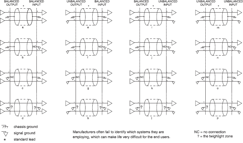
Figure 26.5:
Sixteen different balanced and unbalanced interconnections. Each are the optimised connections for the indicated situations. Note that only four, at the most, can be made with standard 1:1 leads (after Macatee).
The optimisation of sonic purity in many smaller studios is beyond the capacity of many owners, operators and installers of such facilities. This is a reality of the situation in which we find ourselves. Nevertheless, this chapter may not only give some guidance as to how to circumvent many of the common problems, but will also serve to relieve some of the frustration which people may feel when a system which is thought to be relatively simple obstinately refuses to behave correctly. One point to bear in mind at all times is that, in terms of their interconnections, many semi-professional/domestic studios present vastly more complex problems than ultra-expensive studios which use the finest equipment available. When a lesser system fails to operate to perfection, one should not put all of the blame on the technical personnel who installed it, because they may have inherited many intractable problems which have originated in the bad practices of many equipment manufacturers.
It is rather absurd that as a result of this, the most inexpensive equipment tends to require the most expensive installation, but that is what market forces have led to. So many corners have been cut during the manufacturing processes to keep the price of the equipment as low as possible at the point of sale that the problems and extra costs have been passed on to the purchasers in a rather clandestine way. Chaotic marketing free-for-alls are not conducive to good engineering solutions, but for the moment we simply have to live with this reality.
In fact, one of the great driving forces towards all-digital connections is that they leave so many of these problems behind. However, the analogue-to-digital and digital-to-analogue conversions are no easy subject to deal with either, at least where the highest standards of performance are required. The situation seems to be that for as long as microphones and loudspeakers use mechanical diaphragms, and for as long as electric guitars use strings, then these problems are still going to be with us.
26.10 Summary
The analogue audio interfacing of a large studio can be an expensive and complex process.
Much modern recording equipment is not optimally interconnectable.
In many cases, only the use of transformers in the signal path can solve the problems.
Standardisation of compatibility of all the inputs and outputs of a recording system via a 3-pole jackfield/patchbay is an essential feature for flexible and reliable operation.
The sleeve/ground of a 3-pole jack should never carry any signal current. The unbalancing of electronically balanced circuitry may require different treatments depending on circuit design.
The manufacturers should always be referred to before carrying out any unbalancing of electronically balanced circuitry.
Pin 1 of any XLR connector, or the ground/sleeve of a 3-pole jack, should ideally only be connected to the chassis of the equipment, and not to signal ground.
On equipment with dual, balanced and unbalanced inputs and outputs, the most sonically transparent option may not be obvious without experimentation.
Even a ‘standard’ XLR to XLR cable (3-conductors) has been shown to require various different wiring combinations for different grounding configurations. Optimally interfaced audio circuitry will probably be more tolerant of the earthing/grounding of the power supply system.
References
1 Muncy, Neil A., ‘Noise Susceptibility in Analog and Digital Signal Processing Systems’, Journal of the Audio Engineering Society, Vol. 43, No. 6, pp. 435–453, (June 1995)
2 Macatee, Stephen R., ‘Considerations in Grounding and Shielding Audio Devices’, Journal of the Audio Engineering Society, Vol. 43, No. 6, pp. 472–483, (June 1995)
3 Duncan, Ben, ‘The New Age of Radio Defence’, Studio Sound, Vol. 38, No. 10, pp. 85–88, (October 1996)
Bibliography
Giddings, P., Audio System Design and Installation, Focal Press, Boston, USA and Oxford, UK (1995)
Giddings, P., Audio System Design and Installation, Howard W. Sams, Indianapolis, IN, USA (1990)
Journal of the Audio Engineering Society, Vol. 43, No. 6, (June 1995). Issue dedicated to papers on audio system grounding and interconnecting
Davis, D. and Davis, C., Sound System Engineering, Second Edition, Focal Press, Boston, MA, USA (1997)
Davies, D. and Patronis, E., Sound System Engineering, Third Edition, Focal Press, Oxford, UK (2006)