
CHAPTER 2
BUILT-IN INTELLIGENCE
In the previous chapter, you built the Bug Bot, a simple robot that randomly moved in the environment and demonstrated a simple form of bug-like intelligence. In this chapter you will build another robot that is slightly more advanced. This robot will be able to sense the amount of light from a light source in its surroundings and intelligently respond to it. The design of this robot was originally proposed by Valentino Braitenberg; hence we call it the Braitenberg Vehicle Robot or BV-Bot for short. As you will see later, what is special about the BV-Bot is that the source of intelligence in this robot is inherent in its electronic circuitry. In other words, the source of intelligence of the robot—its “brain”—and the robot’s body are inseparable.
The major topics covered in this chapter include the following:
![]() A review of the features and capabilities of BV-Bot
A review of the features and capabilities of BV-Bot
![]() Detailed building instructions for BV-Bot
Detailed building instructions for BV-Bot
![]() Experimenting with BV-Bot
Experimenting with BV-Bot
INTRODUCING THE BRAITENBERG VEHICLE ROBOT (BV-BOT)
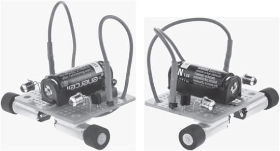
The BV-Bot is a simple robot. It shows that by simply reacting to what is sensed from the environment, a robot can demonstrate intelligent behavior. The BV-Bot consists of two light sensors on the front and two small motors on the sides. Each motor has a wheel on its shaft. Figure 2.1 shows what BV-Bot will look like when it is complete.
Figure 2.1
Two views of BV-Bot: straight connection (left) and crossed connection (right).
© 2014 Behnam Salemi. All Rights Reserved.
With its two light sensors, BV Bot measures the amount of light from a light source in its surroundings. The left and right light sensors generate voltages that are proportional to the amount of light they receive. The output voltage of each sensor is amplified and is applied to each of the two motors on the left and right sides of the robot. The left and right sensors’ output can be connected straight to the left and right motors, respectively, or in a crossed form. The left image in Figure 2.1 shows the straight connection using two patch cords, where the right cable connects the right light sensor to the right motor and the left cable connects the left light sensor to the left motor. The right image in Figure 2.1 shows the crossed form connection. Depending on how the sensors are connected to the motors, the robot will show different behaviors and will either be attracted to the light source or turn away from it.
BV-Bot is easy to build and work with. The components are soldered on a prototyping board, making it robust and lightweight. The battery is placed in a battery holder and is easy to replace. A small switch turns the robot on and off. The patch cords easily plug in and out of the installed pin headers, allowing for a quick change of configuration.
BUILDING BV-BOT
You will create BV-Bot in nine steps:
1. Installing the phototransistors
2. Installing the amplifier transistors
4. Installing the battery holder and on/off switch
5. Connecting the battery holder wiring
6. Installing the wheels
7. Preparing the motors’ assembly
8. Installing the motors’ assembly
9. Installing the caster
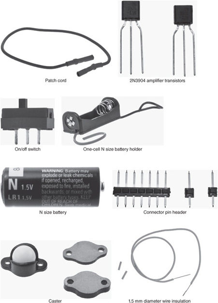
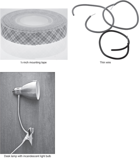
Figure 2.2 provides a complete inventory of the parts needed for building the BV-Bot.
Figure 2.2
The parts inventory list for BV-Bot.

© 2014 Behnam Salemi. All Rights Reserved.
You should be able to purchase these parts online. For detailed information about parts and a list of online vendors who carry them, see Appendix A, “Parts List.”
Installing the Phototransistors
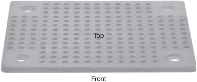
Begin the development of BV-Bot by installing phototransistors on the prototyping board. The prototyping board is rectangular in shape and one of its longer sides will be called the front of the BV-Bot throughout the project. I will refer to the side with copper lamination as the bottom of the board and the other side of the board, without copper lamination, as the top of the board. Figure 2.3 shows the prototyping board and the side selected as the front and the top.
Figure 2.3
The longer side of the prototyping board is selected as the front of the BV-Bot and the side without copper lamination is the top of the board.
© 2014 Behnam Salemi. All Rights Reserved.
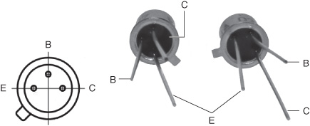
A phototransistor is an electronic component with a glass-covered window on the top to let the light in and three leads called the base (B), emitter (E) and collector (C). The left image in Figure 2.4 shows the schematic and the right image in Figure 2.4 shows a BPW77NA phototransistor that is used in this project. The schematic shows the bottom view of the phototransistor and the tab identifies the emitter. The two other leads are the collector and the base.
Figure 2.4
The schematic and picture of the BPW77NA phototransistor used in the project. The base, emitter, and collector are shown. The metal tab identifies the emitter.
© 2014 Behnam Salemi. All Rights Reserved.
Generally, a phototransistor acts as a switch. When light enters the phototransistor or a voltage is applied to the base, the phototransistor turns on and the collector and emitter, like a switch, are shorted. When there is no light or no voltage applied to the base, the phototransistor is off and the collector and emitter are open. Phototransistors are mainly used for their ability to detect light; usually, their base lead is not used and can be cut. To prepare the phototransistors, follow these steps:
1. Cut the base leads of both phototransistors, as shown in Figure 2.5.
Figure 2.5
The base leads are cut.

© 2014 Behnam Salemi. All Rights Reserved.
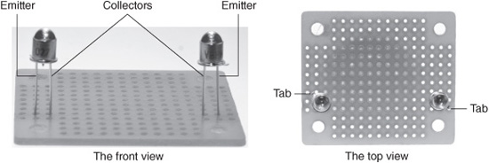
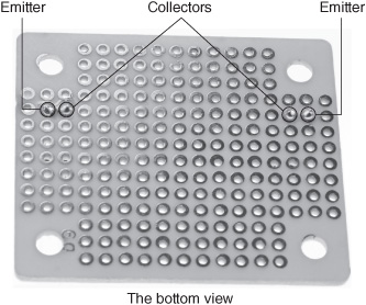
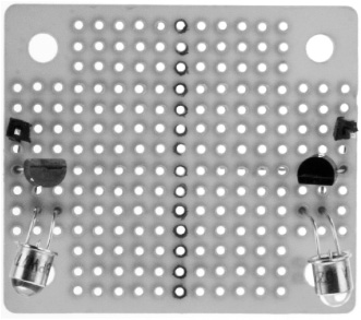
2. Solder the phototransistors to the prototyping board as shown in Figure 2.6. The images in this figure show, from left to right, the front, top, and bottom views of the phototransistors soldered on the prototyping board. As shown by the metal tabs in the top view, the emitters are placed toward the side edges of the board. If you are using a different size prototyping board, the phototransistors should be installed at similar positions relative to the edges of the prototyping board.
Figure 2.6
Different views of how phototransistors are installed on the prototyping board.
© 2014 Behnam Salemi. All Rights Reserved.
Installing the Amplifier Transistors
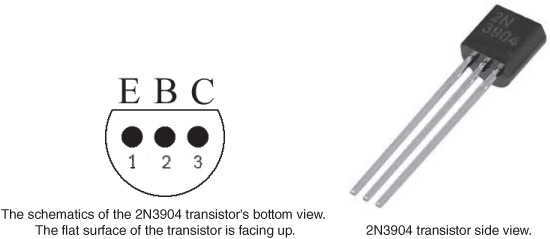
When a phototransistor is turned on in the presence of the light, it is not powerful enough to directly drive a motor. Therefore, it is necessary to use an amplifier to provide enough power to the motor. In this project you will use a transistor as an amplifier. When the phototransistor is turned on, it will turn on an amplifier transistor and the amplifier transistor will drive the motor. The left image in Figure 2.7 is the schematic of the transistor’s bottom view and shows the transistor’s emitter, base, and collector leads. The right image in Figure 2.7 shows the 2N3904 transistor that is used in this project. As you can see, the emitter is on the left when the flat surface of the transistor is facing up. To install the amplifier transistor, follow these steps:
Figure 2.7
Different views of the 2N3904 amplifier transistor.
© 2014 Behnam Salemi. All Rights Reserved.
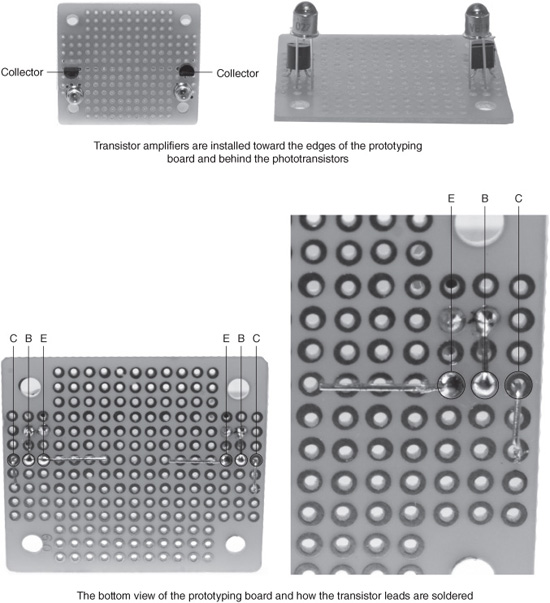
1. Insert the leads of the transistors into the prototyping board as shown in Figure 2.8 such that the collectors are toward the edges of the prototyping board.
2. On the back of the prototyping board, bend the base lead of each transistor toward the emitter of the phototransistor as shown in Figure 2.8. Solder the two leads and cut the extra length of the lead. Note that the phototransistor emitter will be right in front of the base of the amplifier transistor.
Figure 2.8
Installing the transistor amplifier on the prototyping board.
© 2014 Behnam Salemi. All Rights Reserved.
3. On the bottom of the board, bend the emitter of each transistor toward the center line of the prototyping board and solder the lead to the copper circles tabs under the lead as shown in the bottom views of the prototyping board in Figure 2.8. Do not shorten the emitter leads.
4. Bend the collector of each transistor toward the opposite direction as the base and cut the length of the lead such that it reaches over to the second circle tabs down as shown in the bottom views of the prototyping board in Figure 2.8.
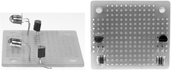
5. Bend the photo transistors 90 degrees toward the front of the BV-Bot as shown in Figure 2.9.
Figure 2.9
Bend the phototransistors 90 degrees toward the front of the robot.
© 2014 Behnam Salemi. All Rights Reserved.
Installing the Pin Headers
To easily change the behavior of the BV-Bot, two pin headers are installed. These allow the phototransistors to connect to either of the motors. To install the pin headers, follow these steps:
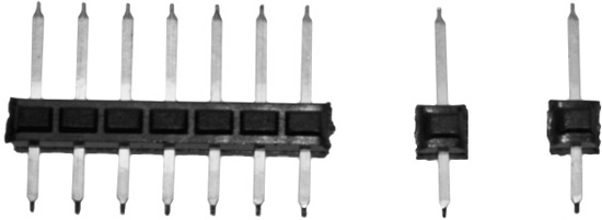
1. Pin headers usually come in rows of 10 or more. Detach two single pin headers with a wire cutter, as shown in Figure 2.10. For this step, make sure you use a pair of safety glasses, as the cut pin headers may become airborne and can be very dangerous!
Figure 2.10
The pin headers. Two pin headers are separated.
© 2014 Behnam Salemi. All Rights Reserved.
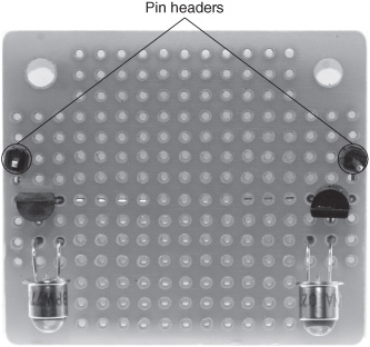
2. Install the pin headers on the prototyping board as shown in Figure 2.11.
Figure 2.11
Install the pin headers on the prototyping board.
© 2014 Behnam Salemi. All Rights Reserved.
3. Figure 2.12 shows the bottom view of the prototyping board where the pin headers are located next to the collectors of the transistor amplifier, as described in step 4 of the previous section. Solder the pin headers to the collectors.
Figure 2.12
The bottom view of the prototyping board, where the pin headers are soldered to the amplifier transistor collectors.

© 2014 Behnam Salemi. All Rights Reserved.
Installing the Battery Holder and On/Off Switch
A suitable battery for the BV-Bot depends on the size and voltage of the selected motors. If the motors are small and low voltage, a small battery will suffice. For larger and higher-voltage motors, a larger battery or two batteries should be used to provide enough power and voltage to run the motors and also last longer. That being said, a too large battery will be heavier as well, which could make the overall robot too heavy for the selected motors to move. Therefore, a balanced approach should be taken. For this project, a single N size battery is used. Depending on the selected battery/batteries, a compatible battery holder should also be selected. To install the battery holder and the on/off switch, follow these steps:
1. Mark the holes on the center line of the board, as shown in Figure 2.13.
Figure 2.13
Mark the center line of the board.
© 2014 Behnam Salemi. All Rights Reserved.
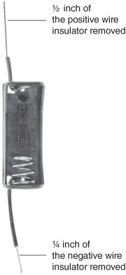
2. Cut the battery holder’s positive (red) and negative (black) wires to about ¾ inch. Then remove ½ inch of the positive wire insulator and ¼ inch of the negative wire insulator, as shown in Figure 2.14.
Figure 2.14
Cut the battery holder’s wires and remove the insulators.
© 2014 Behnam Salemi. All Rights Reserved.
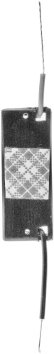
3. Cut a ⅜-inch piece of mounting tape. Remove the cover on one side and stick it on the back of the battery holder at the center, as shown in Figure 2.15.
Figure 2.15
Stick mounting tape on the back of the battery holder.
© 2014 Behnam Salemi. All Rights Reserved.
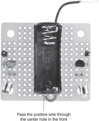
4. Peel off the mounting tape cover. Pass the battery holder positive wire through the first center hole on the front side of the board, which was marked in previous steps, and stick the battery holder to the center of the board, as shown in Figure 2.16.
Figure 2.16
Stick the battery holder onto the center of the board.
© 2014 Behnam Salemi. All Rights Reserved.
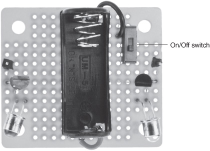
5. Install the on/off switch on the prototyping board and insert the negative wire into a hole next to the switch, as shown in Figure 2.17.
Figure 2.17
Install the on/off switch and insert the negative wire.
© 2014 Behnam Salemi. All Rights Reserved.
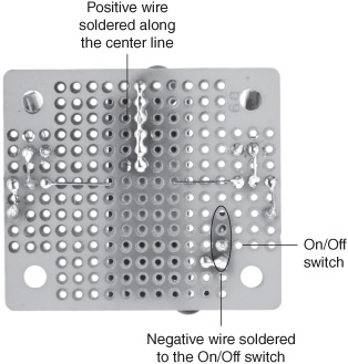
6. Solder the on/off switch and the battery holder’s wires, as shown in Figure 2.18. The negative wire of the battery holder is soldered to a side terminal of the on/off switch and the positive wire is soldered along the center line.
Figure 2.18
Solder the on/off switch and the battery holder’s wires.
© 2014 Behnam Salemi. All Rights Reserved.
Connecting the Battery Holder Wiring
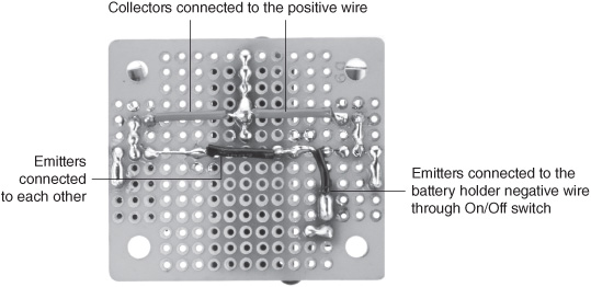
Figure 2.19 shows the wiring connected to the battery holder negative and positive wires. Achieving this consists of the following steps:
Figure 2.19
The battery holder wiring.
© 2014 Behnam Salemi. All Rights Reserved.
1. Connect the transistor amplifiers’ emitters in the middle of the prototyping board to each other by soldering a piece of wire to them.
2. Connect the emitters, which were attached in the previous step, to the negative wire of the battery holder via the on/off switch using a piece of wire.
3. Connect the phototransistors’ collectors to the battery holder positive wire using two pieces of wire.
Installing the Wheels
If the diameter of each motor’s shaft is the same as that of the wheel’scenterhole, installing the wheels on the motor shaft will be very simple. You just need to push the motor shaft into the wheel center hole. In many situations, however, the diameters will not match. The motors selected for this project have a shaft size of 1 mm, while the wheels’ center holes have a diameter of 1½ mm. In this case, a ½ mm thick bushing is required to fill the gap between the motor shaft and the wheel center hole’s inside walls.
Shrink tubes or wire insulators are examples of easy-to-get materials that can be used as the bushing. In this project, a 1½ mm thick wire insulator will be used as the bushing. To use wire insulators as bushing for installing the wheels, follow these steps:
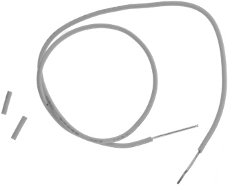
1. Cut two pieces of ⅜-inch insulators and remove them from the wire as shown in Figure 2.20.
Figure 2.20
Using wire insulators as bushing.
© 2014 Behnam Salemi. All Rights Reserved.
2. Push the tip of the insulators into the tip of the motor shaft, as shown in Figure 2.21. It is enough for the insulator to stay on the motor shaft.
Figure 2.21
Pushing the tip of the insulators into the tip of the motor shaft.
© 2014 Behnam Salemi. All Rights Reserved.
3. Insert the wheel into the insulator on the shaft, as shown in Figure 2.22
Figure 2.22
Insert the wheel into the insulator.

© 2014 Behnam Salemi. All Rights Reserved.
4. Gently push the wheel on to the motor shaft, as shown in Figure 2.23. It will pull the insulator as it slides on to the shaft. Make sure a small gap is left between the wheel and the motor wall around the shaft.
Figure 2.23
Gently push the wheel on to the motor shaft.
© 2014 Behnam Salemi. All Rights Reserved.
5. Repeat this process for the other wheel.
Preparing the Motors’ Assembly
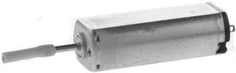
Installing the motors’ assembly of the BV-Bot involves soldering the wires to the motors’ terminals. Two DC motors are used in this project. DC stands for direct current (versus alternating current, or AC), which means these motors work with direct current, the type of current and voltage that batteries provide. DC motors are easy to use. It is possible to change the speed of their rotation by changing the voltage that is applied to them and also change the direction of their rotation by changing the polarity of voltage that is applied to their terminals.
Figure 2.24 shows the schematics of a DC motor where the positive and negative voltage of the battery are connected to the motor’s right and left terminals, respectively, causing the motor to rotate in one direction—for example, left. In Figure 2.25, the polarity of the applied voltage to the motor terminals is reversed. That is, the positive and negative voltage of the battery are connected to the motor’s left and right terminals, respectively, causing the motor to rotate in the opposite direction, which in this example is right.
Figure 2.24
Applying voltage to the motor turns it to the left.

© 2014 Behnam Salemi. All Rights Reserved.
Figure 2.25
Applying the reverse voltage turns the motor to the right.

© 2014 Behnam Salemi. All Rights Reserved.
To prepare the motors’ assembly, follow these steps:
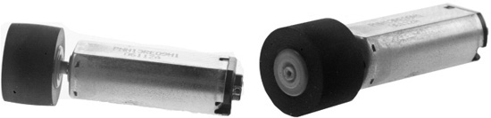
1. Identify the corresponding terminals on the two motors. Usually, at least one of the terminals of the motors is marked with a color or a pattern. Figure 2.26 shows two motors where their positive terminals are marked with a plus sign. If none of the terminals are marked to identify the corresponding terminals, connect each motor to a battery; when both motors turn the same direction, the terminals that are connected to the same battery poles are corresponding terminals. Identifying the corresponding terminals is important to ensure the BV-Bot moves correctly to the right, left, and forward.
Figure 2.26
Identifying corresponding terminals on both motors. The positive terminals are marked with a plus sign.

© 2014 Behnam Salemi. All Rights Reserved.
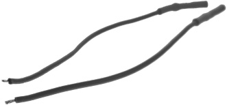
2. Cut the patch cords into two 5-inch pieces, strip the cut ends, and solder them, as shown in Figure 2.27.
Figure 2.27
The patch cords are cut into two 5-inch pieces and the cut ends are stripped and soldered.
© 2014 Behnam Salemi. All Rights Reserved.
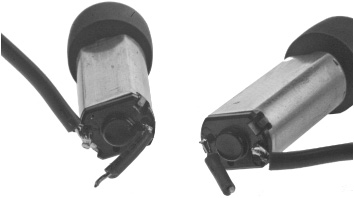
3. Solder the marked terminal of one motor and unmarked terminal of the other motor to a patch cord and solder a ⅜-inch wire to the other terminal, as shown in Figure 2.28.
Figure 2.28
The marked terminal of the right motor and the unmarked terminal of the left motor are attached to the patch cords.
© 2014 Behnam Salemi. All Rights Reserved.
Installing the Motors’ Assembly
The motors’ assembly is now ready to be installed. You will use the ½-inch mounting tape to stick the motors on the prototyping board. The installation consists of the following steps:
1. Cut two ⅜-inch pieces of mounting tape. Remove the cover on one side of each piece and stick both pieces on the prototyping boards, as shown in Figure 2.29.
Figure 2.29
Two ⅜ -inch pieces of mounting tape are attached to the prototyping boards.

© 2014 Behnam Salemi. All Rights Reserved.
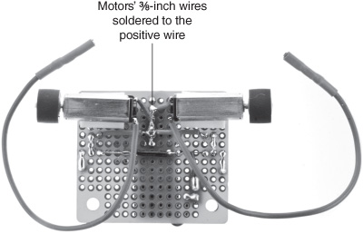
2. Remove the cover on the top of the mounting tape and attach the motors. Then solder the ⅜-inch wires of each motor to the positive wire, as shown in Figure 2.30.
Figure 2.30
Installing the motors’ assembly.
© 2014 Behnam Salemi. All Rights Reserved.
3. Pass the patch cords through the holes on the back of the prototyping board and, for now, plug them in the pin headers as shown in Figure 2.31.
Figure 2.31
Patch cords are passed through the holes on the prototyping board and plugged into the pin headers.
© 2014 Behnam Salemi. All Rights Reserved.
Installing the Caster
The final part that will be added to the BV-Bot is a simple and lightweight caster. To install the caster, follow these steps:
1. Cut a ⅜-inch piece of mounting tape. Remove the cover on one side of the piece and stick it on the back of the center line, on the bottom of the prototyping board, as shown in Figure 2.32.
Figure 2.32
Attach a ⅜ -inch piece of mounting tape on the center line.

© 2014 Behnam Salemi. All Rights Reserved.
2. Peel the cover from the mounting tape and stick the caster centered on the tape, as shown in Figure 2.33.
Figure 2.33
Installing the caster.

© 2014 Behnam Salemi. All Rights Reserved.
EXPERIMENTING WITH BV-BOT
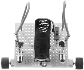
Figure 2.34 shows the BV-Bot in its complete form and in two different configurations. The left image in Figure 2.34 shows the straight configuration, in which the left patch cord connects the left motor to the left phototransistor output and the right patch cord connects the right motor to the right phototransistor output. The right image in Figure 2.34 shows the crossed configuration, in which the left patch cord connects the left motor to the right phototransistor output and the right patch cord connects the right motor to the left phototransistor output.
Figure 2.34
BV-Bot in straight configuration (left) and crossed configuration (right).

© 2014 Behnam Salemi. All Rights Reserved.
In this section, you will perform two experiments that will illustrate how BV-Bot behaves differently in the presence of light with these two configurations. Go ahead and turn on the BV-Bot.
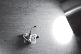
Straight-Configuration BV-Bot Avoids Light
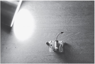
Figure 2.35 shows the top view of a desk lamp shining light at a straight-configuration BV-Bot from the left side. In this position, the left phototransistor receives more light from the desk lamp than the right phototransistor. This will cause the left transistor amplifier connected to the left phototransistor to output more voltage. As a result, the left motor, which in the straight configuration is connected to the left phototransistor, will receive more voltage. The additional voltage will cause the left motor to turn much faster than the right motor, which will drive the BV-Bot toward the right side and away from the light source.
Figure 2.35
The straight-configuration BV-Bot moves to the right and avoids the light.
© 2014 Behnam Salemi. All Rights Reserved.
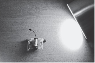
Figure 2.36 shows the top view of the case where the desk lamp is shining light at the same BV-Bot from the right side. In this situation, the right phototransistor receives more light from the desk lamp than the left phototransistor. This causes the right transistor amplifier connected to the right phototransistor to output more voltage. As a result, the right motor, which in the straight configuration is connected to the right phototransistor, will receive more voltage. The additional voltage will cause the right motor to turn much faster than the left motor, which in this case will drive the BV-Bot toward the left side and again away from the light source.
Figure 2.36
The straight-configuration BV-Bot moves to the left and avoids the light.
© 2014 Behnam Salemi. All Rights Reserved.
Crossed-Configuration BV-Bot Is Attracted to the Light
Figure 2.37 shows the top view of a desk lamp shining light at a crossed-configuration BV-Bot from the left side. In this position, the left phototransistor receives more light from the desk lamp than the right phototransistor. This causes the left transistor amplifier connected to the left phototransistor to output more voltage. As a result, the right motor, which in the crossed configuration is connected to the left phototransistor, will receive more voltage. The additional voltage will cause the right motor to turn much faster than the left motor, which will drive the BV-Bot toward the left side and toward the light source.
Figure 2.37
The crossed-configuration BV-Bot moves to the left and toward the light.

© 2014 Behnam Salemi. All Rights Reserved.
Figure 2.38 shows the top view of the case where the desk lamp is shining light at the same BV-Bot from the right side. In this situation, the right phototransistor receives more light from the desk lamp than the left phototransistor. This causes the right transistor amplifier connected to the right phototransistor to output more voltage. As a result, the left motor, which in the crossed configuration is connected to the right phototransistor, will receive more voltage. The additional voltage will cause the left motor to turn much faster than the right motor, which in this case will drive the BV-Bot toward the right side and again toward the light source.
Figure 2.38
The crossed-configuration BV-Bot moves to the right toward the light source.
© 2014 Behnam Salemi. All Rights Reserved.
SUMMARY
In this chapter, you built a robot called the BV-Bot. The original design of this robot was proposed by Valentino Braitenberg. The BV-Bot was more advanced than the Bug Bot. It had two light sensors and two motors, and was configurable to either straight or crossed configurations. The straight-configuration tendency was to avoid light. This is similar to the behavior of some cockroaches that run away from the light and hide in dark corners. In contrast, the crossed-configuration BV-Bot illustrated the tendency of being attracted to the light. This behavior is similar to the behavior of some moths that move toward a light source.
Showing consistent responses to environmental conditions such as the amount of light is an example of an intelligent behavior that we see from cockroaches and moths. BV-Bot showed similar intelligent behavior. An interesting characteristic of BV-Bot was that the source of its intelligence was built into its hardware, and that changing its wiring changed its intelligent behavior.