
CHAPTER 3
SENSING AND ACTING
In Chapter 1, “The Runaway Robot, or Bug-Like Intelligence,” you built the Bug Bot, a straightforward robot that randomly moved in the environment and demonstrated a simple form of bug-like intelligence. In Chapter 2, “Built-in Intelligence,” you built the BV-Bot, which was able to sense the light in its surroundings and, depending on how it was configured, respond by moving either toward the light source or away from it. In this chapter, you will use your imagination to create a “story” that can explain how Bug Bot and BV-Bot work. It also discusses why sensing the surroundings and acting in the environment are important in robotics and looks at a number of different ways robots can sense and act.
The major topics covered in this chapter include the following:
![]() A review of the features and capabilities of Bug Bot and BV-Bot
A review of the features and capabilities of Bug Bot and BV-Bot
![]() Creating a story about how Bug Bot and BV-Bot work
Creating a story about how Bug Bot and BV-Bot work
![]() Examples of different types of sensors for robots
Examples of different types of sensors for robots
![]() Examples of different types of actuators for robots
Examples of different types of actuators for robots
A REVIEW OF BUG BOT AND BV-BOT CAPABILITIES
Without focusing on how Bug Bot and BV-Bot were built, let’s review how they performed and behaved in the environment. You saw how Bug Bot moved. It randomly bounced around in its environment. When it hit an obstacle, sometimes it kept pushing against the obstacle for a while and backed up, and sometimes it quickly changed its direction and randomly turned to the left or right. Also, in some rare occasions, it may have lost its balance and ended up on its belly or fell off the table and you had to put it back on its feet again! Probably anyone who looks at Bug Bot running in its environment will continue to see different combinations of all the above actions, namely moving forward, moving backward, turning left, turning right, and sometimes falling.
BV-Bot was more advanced in the sense that its actions were not purely random. BV-Bot was able to sense the intensity of the light in its surroundings and could be configured into two modes by connecting its patch cords either in a straight or crossed manner. In straight-connection mode, BV-Bot showed an “avoiding the light” behavior, by detecting where the light source was and turning away from it. In crossed-connection mode, BV-Bot showed an “attraction to the light” behavior, again by detecting the light source but this time turning toward it. In cases where the light source was exactly in front of the robot, both light sensors received the same amount of light, causing BV-Bot to move forward. As you saw, BV-Bot motors could turn in only one direction, allowing the robot to move forward, turn left, or turn right, but not move backward.
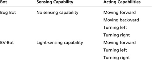
Table 3.1 summarizes the sensing and acting capabilities of Bug Bot and BV-Bot. As you can see, Bug Bot had no sensing capability and was able to perform four actions while BV-Bot had one sensing capability and was able to perform three actions.
Table 3.1 A Summary and Comparison of Bug Bot’s and BV-Bot’s Sensing and Action Capabilities
IMAGINATION CORNER
Now let’s use our imagination to make a “story” about how Bug Bot and BV-Bot work. Scientists also make stories to explain how things work, such as different natural phenomena or newly invented systems like robots—although in science, they are called “theories” rather than “stories.” Usually, stories or theories that are simpler and can explain how more things work are considered “better.” Therefore, the goal here will be to write a simple story that can explain how both Bug Bot and BV-Bot work.
Based on the sensing and acting capabilities of Bug Bot and BV-Bot outlined in the previous section, one possible story could be as follows: An imaginary “decision-maker” is sitting inside the Bug Bot or BV-Bot and its job is to select the next action the robot must perform based on what the robot is sensing.
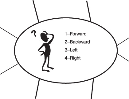
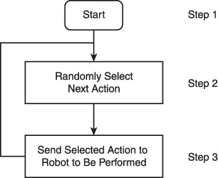
Bug Bot does not have any sensing capabilities; therefore, the imaginary decision-maker keeps selecting a random action from its four possible actions to perform. Figure 3.1 shows the imaginary decision-maker sitting inside Bug Bot randomly selecting from the four possible actions. Figure 3.2 shows the steps that the imaginary decision-maker inside Bug Bot follows to make its decisions. Step 1 is the “start” step. This corresponds to when the robot is turned on. The arrow from the start step shows the next step, step 2. In this step, an action is randomly selected. The arrow going out of step 2 shows the next step, step 3. At the third step, the decision-maker sends the selected action to the robot to be performed. After step 3, the decision-maker goes back to step 2 to select the next random action and continues to loop through steps 2 and 3 as long as the robot is on.
Figure 3.1
The imaginary decision-maker sitting inside Bug Bot, randomly selecting what action the robot must perform.
© 2014 Behnam Salemi. All Rights Reserved.
Figure 3.2
The flowchart of the steps that the imaginary decision-maker follows.
© 2014 Behnam Salemi. All Rights Reserved.
Note
The method of representing a sequence of decision-making steps shown in Figure 3.2 is called a “flowchart.” Flowcharts are diagrams that use arrows, rectangles, and other shapes to specify a sequence of steps and the instructions for going from one step to another. You will see more examples of flowcharts in the coming sections.
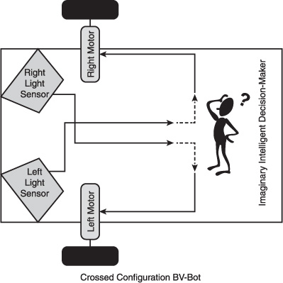
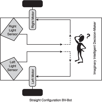
For BV-Bot, which has light-sensing capabilities and three actions, the story will involve the imaginary decision-maker sitting inside BV-Bot, measuring the intensity of light that enters from the left and right light sensors. If light is detected, the decision-maker will engage the motor connected to that sensor; the more light enters the sensor, the faster the motor connected to that sensor will turn. Figure 3.3 and Figure 3.4 show the BV-Bot sensors, motors, and its decision-maker in the crossed and straight configurations, respectively.
Figure 3.3
Light sensors, motors, and the imaginary decision-maker sitting inside the BV-Bot in a crossed configuration.
© 2014 Behnam Salemi. All Rights Reserved.
Figure 3.4
Light sensors, motors, and the imaginary decision-maker sitting inside the BV-Bot in a straight configuration.
© 2014 Behnam Salemi. All Rights Reserved.
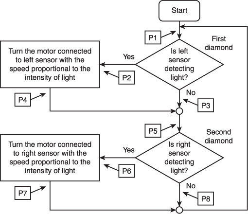
Figure 3.5 shows the flowchart of the steps that the decision-maker in the BV-Bot follows. The starting point of this flowchart is again the start step. There are two diamonds in this flowchart. A diamond in a flowchart shows a point of decision-making based on a question. A diamond has one input arrow and two or more output arrows. The output arrows are labeled with the values of interest resulting from the question.
Figure 3.5
The flowchart of the steps that the BV-Bot imaginary decision-maker follows.
© 2014 Behnam Salemi. All Rights Reserved.
After the start step, the input arrow of the first diamond is reached, which is P1 in Figure 3.5. The question of this diamond is, “Is left sensor detecting light?” If the answer is yes, the exit from the diamond will be the output arrow with the “Yes” label (P2). If the answer is no, the exit from the diamond will be the output arrow with the “No” label (P3). If light is detected, the imaginary decision-maker will enter the rectangle marked “P2” and will turn the motor that is connected to the left light sensor. The more light is detected, the faster the motor will be turned.
After exiting the first diamond either through the “Yes” arrow (from P2 to P4) or the “No” arrow (from P3), the decision-maker reaches the second diamond (P5), which asks the same question for the right light sensor. If the answer is yes, the exit from the diamond will be the output arrow with the “Yes” label (P6). If the answer is no, the exit from the diamond will be the output arrow with the “No” label (P8). If light is detected, the imaginary decision-maker will enter the rectangle marked “P6” and will turn the motor that is connected to the right light sensor. The more light is detected, the faster the motor will be turned.
After leaving the second diamond either through the “Yes” arrow (from P6 to P7) or the “No” arrow (from P8), the decision-maker goes back to enter the first diamond at P1 and continues to loop through as long as the robot is on.
As you can see, the imaginary decision-maker in the BV-Bot follows the same flowchart for both the straight and crossed configurations. In addition, the behavior of the BV-Bot to avoid or to be attracted to the light depends on how its patch cords are configured.
Emergent Actions or Behaviors
You may have noticed that the story of BV-Bot did not talk about the moving-forward action. Likewise, in the BV-Bot flowchart in Figure 3.5, there was no step for moving forward. There were only actions to engage the left motor and the right motor, causing the robot to turn right and turn left, respectively. The moving-forward action does not need to be explicitly part of the story or the flowchart, however. The story and flowchart of BV-Bot can automatically create the moving-forward action when both left and right light sensors receive the same amount of light. In this case, both motors turn at the same speed, causing the robot move straight forward. This is an example of an action that is the result of a combination of a number of other actions, and it is called the “emergent action” or “emergent behavior.” An emergent action is an action that is the result of the interaction or combination of other actions.
Intelligent Robots
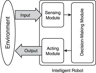
Figure 3.6 shows three main elements of the Bug Bot and BV-Bot story:
![]() The sensing module, to sense some features of the environment
The sensing module, to sense some features of the environment
![]() The decision-making module, to choose an action based on the sensing data
The decision-making module, to choose an action based on the sensing data
![]() The acting module, to execute an action to make an impact on the environment
The acting module, to execute an action to make an impact on the environment
Figure 3.6
A general model of an intelligent robot.
© 2014 Behnam Salemi. All Rights Reserved.
These elements are not tied to the mechanical or electrical hardware of the Bug Bot or BV-Bot. This makes the story of Bug Bot and BV-Bot a general story applicable to many other types of robots that have similar modules. For example, consider a vacuum-cleaning robot. The sensing capabilities of a vacuum-cleaning robot include sensing the floor, walls, and stairs; dust and trash; which room in the house it is cleaning; and so on. The actions of the vacuum-cleaning robot include moving in different directions in the environment, vacuuming trash, making different kinds of beeping noises to announce what it is doing, charging automatically, and so on. The decision-making module decides what action to perform at every moment based on the sensing data.
As another example, let’s try to identify the three modules in a human being. Our five senses—sight, hearing, taste, smell, and touch—are our sensing capabilities. Our actions consist of moving muscles for walking, running, grabbing, and pushing, as well as speaking and making sounds. Our decision-making module consists of our brain and spinal cord.
The general model of an intelligent robot in Figure 3.6 suggests that the source of intelligence in a robot lies in its ability to make intelligent decisions. If the decision-making module of a robot, using input from the sensing module, can select an action that a human being finds reasonable, we call that robot an intelligent robot.
SENSING DEVICES FOR ROBOTS
In this section, you will see examples of different types of devices that can be used as sensing devices in robots. What is common among all these devices is their ability to measure an aspect of the robot itself, such the robot’s speed or the surrounding environment (for example, the room temperature), and convert them into electric signals. Sensors usually need to be accompanied by an electronic circuit to operate. Designing such circuits is mainly specific to each sensor and too advanced a topic for this book. However, sensor manufacturers usually include sample circuits in a sensor’s datasheet, which are good sources of information for using the sensors.
When the values that the sensor is measuring are converted to electric signals by the electronic circuit, the robot can use them in its decision-making. For example, you saw in Chapter 2 how light sensors were used in BV-Bot to convert the light to electric signals, which, after amplification, were used to drive the BV-Bot motors. In the next chapter, you will see more examples of such sensors. The goal of this section is not to give an exhaustive list of all sensing devices, but to give you an understating of what sensors are and to introduce a number of useful sensing devices that you can use in your future projects.
Light Sensors
Light sensors are used to detect or measure the intensity of light in the environment. Light sensors are useful when a robot is programmed to do certain tasks—for example, when there is daylight or to find the location of a light source. You saw an example of light sensors in the previous chapter, where the BV-Bot used two light sensors to move either toward or away from a light source. There are various ways to detect light.
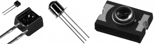
Photodiodes
A photodiode is an electronic component with a glass-covered window to let the light in. It has two leads, called a cathode and an anode. The shorter pin is the cathode and the longer pin is the anode. The more light enters the photodiode, the better conductivity it will have. That means when more light shines on the photodiode, more electricity can go through the photodiode. Figure 3.7 shows examples of photodiodes.
Figure 3.7
Examples of photodiode light sensors.
© 2014 Behnam Salemi. All Rights Reserved.
Phototransistors
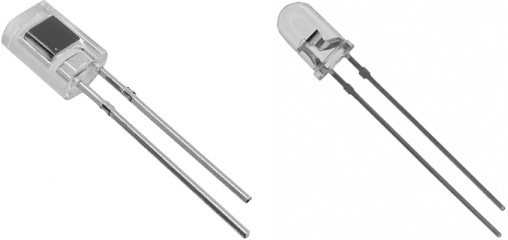
A phototransistor is a special kind of transistor for measuring the intensity of light. Similar to a regular transistor, a phototransistor has three leads: the base (B), emitter (E), and collector (C). It also has a glass-covered window to let the light in. When light enters the phototransistor, the phototransistor turns on, and the resistance between the collector and emitter reduces. If enough light enters the transistor, the transistor will saturate, meaning that the resistance between the emitter and collector will go to zero (will be shorted) and the transistor will act like a closed switch. When there is no light, the phototransistor is off, and the connection between the collector and emitter is open. Phototransistors are mainly used for their ability to detect light, and their base lead is usually not used. Indeed, in some photo transistors, the base lead is missing; these types of phototransistors have only two leads. Figure 3.8 shows examples of phototransistors.
Figure 3.8
Examples of phototransistor light sensors.
© 2014 Behnam Salemi. All Rights Reserved.
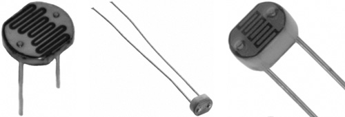
Photo Resistors
Photo resistors are resistors whose resistance changes with the amount of light they get. That is, the amount of current that passes through them varies depending on the amount of light they get. The change in current is what the electronic circuit detects. Photo resistors have two interchangeable leads and a window to receive light. Figure 3.9 shows examples of photo resistors.
Figure 3.9
Examples of photo resistor light sensors.
© 2014 Behnam Salemi. All Rights Reserved.
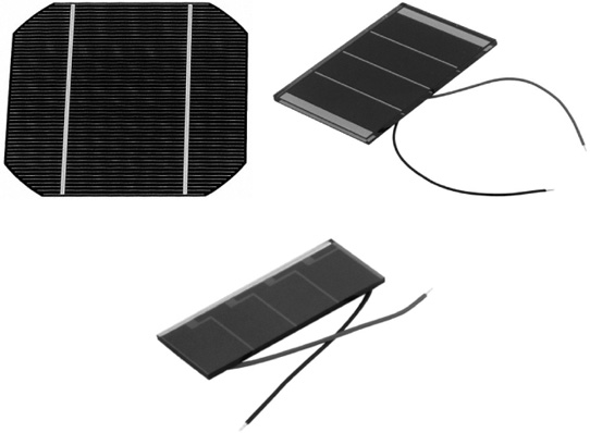
Solar Cells
A solar cell generates electricity in the presence of light; this characteristic can be used to detect light. The amount of generated electricity is proportional to the amount of received light. Figure 3.10 shows examples of solar cells.
Figure 3.10
Examples of solar cell light sensors.
© 2014 Behnam Salemi. All Rights Reserved.
Infrared Sensors
In addition to visible light detectors, there are light sensors for detecting infrared light. Red light has the lowest-frequency light in the visual spectrum, and infrared light has a lower frequency than red light, which is why it is called infra-red. Infrared light is not visible to human eyes. Some photo diodes and phototransistors are made to be sensitive to infrared light instead of visible light, and can be used to detect infrared light. Any hot surface emits infrared light. Other sources of infrared are infrared light bulbs and infrared light emitting diodes (LEDs). Pairs of infrared LEDs and photo-transistors are used in remote-control devices such as traditional TV remote controls and Nintendo Wii remotes. Robots can use infrared emitters and detectors to communicate with each other or to receive commands from a remote controller from short distances—about 30 feet (10 meters).
Bump Sensors
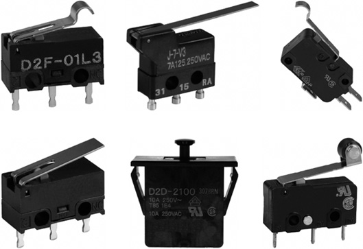
When a robot moves around in an environment, it is highly desirable for it to be able to detect when it collides with a wall or an object. A simple way to achieve this is to install a switch on a face of the robot to serve as a bump sensor. This switch will be turned on when the robot makes contact with an object. Figure 3.11 shows examples of switches called snap-action or limit switches that can be used as bump sensors. As you can see in Figure 3.11, all these switches have an extended arm that turns the switch on when pushed. If they are installed on the robot such that the arm is the first point of contact with an object, the robot can detect when it bumps into an object by checking the status of the switch.
Figure 3.11
Examples of snap-action or limit switches for bump sensors.
© 2014 Behnam Salemi. All Rights Reserved.
Distance Sensors
A robot with only touch sensors can sense the objects in its surrounding only when it bumps into them. This is similar to a person in a room who has his eyes closed, holding his hands in front of him as touch sensors and trying to find the exit door. This person will move around cautiously in random directions until one of his hands touches a wall or, if he is lucky, the door! After finding a wall, the person will probably follow that wall to the left or right and go around the room to find the door. This will be a slow process, requiring lots of walking around. If the room is fairly large it might take quite some time. And if there other objects in the room, such as furniture, finding the door will be even more difficult.
In contrast, if this person opens his eyes, he will be able to look around from where he is without moving, find the door, and then move directly toward it. This will be much faster and safer, and requires the person to expend much less energy. For humans, the ability to see is the ability to detect objects in distance. There are a number of ways the robots can detect objects in distance as well.
Sonar Sensors
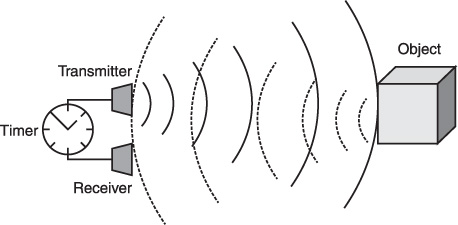
A way of measuring distance is to use sonar. Sonar measures distance by sending pulses of sounds and measuring the duration between when the pulse was sent and the when a reflection of the pulse bouncing off of a nearby object was received. The duration, or travel time, is the time it takes for the pulse to travel at the speed of sound to the object and return back to the sensor. Because the pulse’s travel time and the speed of sound are known, the distance can be calculated by multiplying half of the travel time (the time it took for the pulse to travel to the object) by the speed of sound.
A sonar sensing device consists of a sound pulse transmitter, a sound receiver, and a timer. The timer starts keeping the time when the transmitter sends a pulse and stops when the receiver receives the reflected pulse. Figure 3.12 shows a sonar sensor detecting an object. The solid curved lines show the pulse sent by the transmitter, and the dashed curved lines show the reflection bounced off of the object.
Figure 3.12
A sonar sensor detecting an object.
© 2014 Behnam Salemi. All Rights Reserved.
Laser Range Finders
Laser range finders, or LIDARs, use laser beams to measure the distance to an object. Different laser range finders work using different methods. One type uses the same principle as sonar sensors, but instead of sound pulses they use laser beams. Because the speed of light is much higher than the speed of sound, and because laser beams are more focused than sound waves, LIDARs are faster and measure farther distances than sonar sensors. This makes LIDARs more effective, especially when objects or the robot itself are moving during measurements. LIDARs are usually very expensive. Figure 3.13 shows examples of commercially available laser range finders systems from Sick.
Figure 3.13
Examples of commercially available laser range finders systems from Sick.

© 2014 Sick.com. All Rights Reserved.
Infrared Proximity Sensors
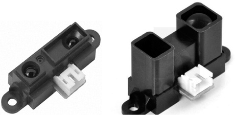
Infrared proximity sensors use an infrared beam to measure the distance to an object. These sensors consist of an infrared transmitter and a receiver. The infrared transmitter sends a beam of infrared light, which reflects off the object and reaches the receiver. The receiver estimates the distance based on the intensity of the reflected infrared light. If the object is far away, the reflection will have a lower intensity; when the object is close, the reflection will have a higher intensity. Figure 3.14 shows commercially available infrared proximity sensors from Sharp. Infrared proximity sensors measure up to around 1 meter (3 feet) and are inexpensive, making them a good choice for measuring distance in low-cost projects.
Figure 3.14
Examples of commercially available infrared proximity sensors from Sharp.
© 2014 Behnam Salemi. All Rights Reserved.
Other Sensors
There are many sensors that can be used in robots. All these sensors convert the value that they measure into an electric signal so that the robot can read and use it in its decision-making. Some other useful sensors include the following:
![]() Microphones, to detect noise or sound in the environment
Microphones, to detect noise or sound in the environment
![]() Temperature sensors, to measure the environment temperature
Temperature sensors, to measure the environment temperature
![]() Motion sensors, to detect motion
Motion sensors, to detect motion
![]() Pressure sensors, to measure pressure
Pressure sensors, to measure pressure
![]() Accelerometers, to measure acceleration
Accelerometers, to measure acceleration
![]() Shaft encoders, to detect the position of a rotating shaft
Shaft encoders, to detect the position of a rotating shaft
Devices such as cameras are also considered sensors. They provide images of the environment, which the robot can use to detect where it is—for example, if it is in the kitchen or the living room. Also, the images can be used for face recognition. The robot can recognize the people around it and consider with whom it is interacting in its decision-making. For example, the robot can react differently to a child than an adult, or a security robot might call the police if it sees an unrecognized face in the house!
ACTING DEVICES FOR ROBOTS
In this section, you will see examples of different types of devices that can be used as acting devices or actuators in robots. What is common among all these devices is their ability to perform an action and make an impact in the environment—for example, to move an object or the robot itself. In the previous chapter, you saw that the two DC motors used in the BV-Bot were driven by two transistors. In the next chapter, you will see more examples of actuators.
For their operation, actuators are also accompanied by electronic circuits called “drivers.” The robot decision-maker will send a command to the driver circuit to perform the action—for example, engage a motor. Then, the driver circuit translates the robot’s command to the right amount of voltage and current to engage the motor. The driver isolates the robot decision-maker from the specifics of the actuators’ operation so that if, for example, a DC motor were replaced by an AC motor, only the driver would need to be changed. The robot could still use the same command.
The goal of this section is not to provide an exhaustive list of all acting devices and a detailed description of how they operate, but to give you an understanding of what actuators are and to introduce a number of useful acting devices that you can use in your future projects.
Motors
Motors are currently the main source of movement in robots. DC motors are motors that work with direct current. There are two types of DC motors:
![]() Brushed DC motors. In brushed DC motors, two brushes are used to provide electricity to the rotating core of the motor (commutator), which is an electric magnet surrounded by a permanent, stationary magnet called a stator.
Brushed DC motors. In brushed DC motors, two brushes are used to provide electricity to the rotating core of the motor (commutator), which is an electric magnet surrounded by a permanent, stationary magnet called a stator.
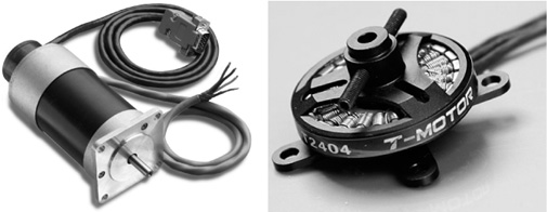
![]() Brushless DC motors. In brushless DC motors, the rotating core (commutator) is a permanent magnet and is surrounded by a stationary electric magnet (stator). Because the electric magnet does not rotate, no brushes are needed.
Brushless DC motors. In brushless DC motors, the rotating core (commutator) is a permanent magnet and is surrounded by a stationary electric magnet (stator). Because the electric magnet does not rotate, no brushes are needed.
By changing the applied voltage to a brushed DC motor, you can change the motor’s rotation speed; by changing the polarity of the applied voltage, you can change the rotation direction. For brushless DC motors, computerized power electronics circuits are used to drive the motors. Figure 3.15 shows examples of brushed DC motors, while Figure 3.16 shows examples of brushless DC motors.
Figure 3.15
Examples of brushed DC motors.
© 2014 Behnam Salemi. All Rights Reserved.
Figure 3.16
Examples of brushless DC motors.
© 2014 Behnam Salemi. All Rights Reserved.
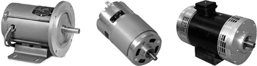
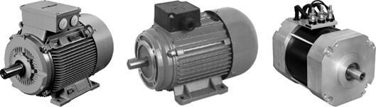
Another type of motor is an AC motor. AC motors use alternating current. Changing the rotation speed of an AC motor requires changing the frequency of the AC voltage applied to the motor. Changing the direction of rotation in an AC motor is not as easy as changing the direction of a DC motor. Figure 3.17 shows examples of AC motors.
Figure 3.17
Examples of AC motors.
© 2014 Behnam Salemi. All Rights Reserved.
RC Servo Motors
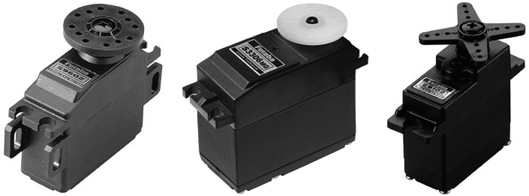
RC servo motors are used by hobbyists in remote control (RC) models to control the position of the steering wheels of RC cars, the flight control surfaces of RC airplanes, and other types of radio-controlled models such as boats, helicopters and so on. RC servos are easy to control and are commercially available in different sizes and strengths, which make them ideal actuators for many robotics projects. Figure 3.18 shows examples of RC servo motors.
Figure 3.18
Examples of RC servo motors.
© 2014 Behnam Salemi. All Rights Reserved.
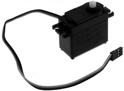
RC servos are controlled by three wires. Figure 3.19 shows the connector and wires that are connected to an RC servo. Two wires supply the positive and negative voltages to the RC servo—usually red and black, respectively. The third wire, which is usually white or yellow, specifies the desired position of the servo arm in the form of an electric pulse.
Figure 3.19
The connector and wires that are connected to an RC servo.
© 2014 Behnam Salemi. All Rights Reserved.
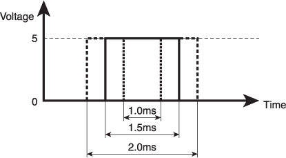
Figure 3.20 shows the electric pulse specifying the position of an RC servo. A pulse with a width of 1.5 milliseconds specifies the center position of the RC servo arm. Reducing the width of the pulse to 1.0 millisecond incrementally moves the RC servo arm all the way to one direction; increasing it to 2.0 milliseconds moves the servo arm position all the way to the other direction. For the RC servo to hold its position, a sequence of such pulses are periodically sent to the RC servo.
Figure 3.20
Timing of the pulse that controls the position of an RC servo arm.
© 2014 Behnam Salemi. All Rights Reserved.
Other Actuators
Many other types of actuators are used to generate movements and actions in robots. Some other useful actuators include the following:
![]() Stepper motors. These are special types of motors that rotate in small steps when triggered by electric pulses. Each step is usually a few degrees, so the motor might make a complete rotation in, for example, 100 to 200 steps. Stepper motors are more effective when the goal is to specifically hold the motor shaft in different positions as opposed to continuously rotating it. Stepper motors hold their current position as long as they are connected to a power supply. Stepper motors are open-loop actuators, meaning that a stepper motor’s controller cannot sense the current position of the motor shaft. These motors are easier to control than servo motors, which require a closed feedback loop that detects the position of the motor shaft at each moment to hold a specific position.
Stepper motors. These are special types of motors that rotate in small steps when triggered by electric pulses. Each step is usually a few degrees, so the motor might make a complete rotation in, for example, 100 to 200 steps. Stepper motors are more effective when the goal is to specifically hold the motor shaft in different positions as opposed to continuously rotating it. Stepper motors hold their current position as long as they are connected to a power supply. Stepper motors are open-loop actuators, meaning that a stepper motor’s controller cannot sense the current position of the motor shaft. These motors are easier to control than servo motors, which require a closed feedback loop that detects the position of the motor shaft at each moment to hold a specific position.
![]() Shape memory alloys (SMAs). An SMA is a wire-shaped actuator whose length is considerably shortened when heated by an external hot object or by passing an electrical current through it. SMAs use this characteristic to simply move a robot part or other object.
Shape memory alloys (SMAs). An SMA is a wire-shaped actuator whose length is considerably shortened when heated by an external hot object or by passing an electrical current through it. SMAs use this characteristic to simply move a robot part or other object.
![]() Solenoids. These are magnetic actuators. A solenoid uses an electromagnet to push or pull a metal core, which in turn is used to move an object such as a robot part.
Solenoids. These are magnetic actuators. A solenoid uses an electromagnet to push or pull a metal core, which in turn is used to move an object such as a robot part.
![]() Linear actuators. These can directly move other objects on a straight line. This is in contrast to the motors that only rotate. Some linear actuators use gears to convert the rotational movement of a motor into linear movement.
Linear actuators. These can directly move other objects on a straight line. This is in contrast to the motors that only rotate. Some linear actuators use gears to convert the rotational movement of a motor into linear movement.
![]() Speakers and LEDs. Speakers and LEDs generate sound and light in their surroundings, respectively, which is considered an action. Robots use actuators such as speakers and LEDs to send information and communicate with their surroundings.
Speakers and LEDs. Speakers and LEDs generate sound and light in their surroundings, respectively, which is considered an action. Robots use actuators such as speakers and LEDs to send information and communicate with their surroundings.
SUMMARY
In this chapter, you learned how to conceptualize the sensing capabilities and actions of a robot and develop general stories/theories about how the robots work. You also looked at representing a sequence of decision-making steps in a flowchart and learned about the concepts of emergent behavior and intelligent robots. Finally, you looked at why sensing the surroundings and acting in the environment are important in robotics, as well as a number of different ways robots can sense and act.