
CHAPTER 6
WHO ELSE IS USING DIGITAL BRAINS?
In this chapter, you will look at examples of the state-of-the-art in robotics technology. All the robotic systems covered in this chapter use a digital brain to implement flexible and powerful robots that are capable of performing complex tasks. Today, many intelligent robots are designed to help people by performing tasks in places in which it could be dangerous or difficult for people to work such as underwater, in the air, in outer space, on the road, or in factories. Others provide services in homes, such as autonomously vacuuming the carpet and providing security.
To perform complex tasks, these robots usually need to collect large amounts of information about their surroundings. Therefore, most of them use numerous sensors to gather different kinds of information—such as video, audio, temperature, pressure, motion, and so on—from their environment. One or more powerful computers and micro-controllers usually process the collected data and decide what action or actions need to be taken. After the action or actions are selected, the robot uses its actuators to perform the action(s). Depending on the complexity of the selected task, performing these actions may require extremely precise and dexterous actuators.
One example of such a robot is a mobile robot that can autonomously drive a vehicle on the road. This robot uses a number of video cameras, laser range finders, speedometers, and GPS sensors to sense the environment. One or multiple powerful computers run the programs to process the video streams from the cameras and distance data from the laser range finders to detect the road, traffic signs, pedestrians, other vehicles, and obstacles. In addition, it uses the GPS sensor and a map to detect where it is and to generate a path from its current location to a given destination. The output of the control program is a sequence of actions such as acceleration, braking, steering, turning, and maybe honking that the robot needs to perform to navigate to its destination. The robot hardware and control software should reliably work at night as well as on sunny and rainy days, should be extra cautious when people are around, and should take an alternate path if there is an accident on the road. There is also the real-time constraint that makes the driving task even more challenging. While the robot is driving—for example, at 60 mph—it has only a fraction of a second to detect and safely avoid an obstacle on the road.
Although some of the robots you will see in this chapter are very complex systems with elaborate hardware and extensive control software, at their core, they generate their intelligent behavior by looping through the same three-step approach that you saw in previous chapters:
1. Sensing the environment
2. Selecting actions based on the sensed data
3. Performing the selected actions in the environment
In the rest of this chapter, each section introduces a state-of-the-art robot, briefly talks about its history and applications, and looks at its sensors, computational power, and actuators.
ASIMO HUMANOID ROBOT
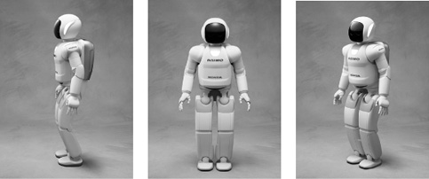
Figure 6.1 shows three views of the Advanced Step in Innovative Mobility (ASIMO) robot. ASIMO is the result of more than two decades of research and development by scientists and engineers at Honda. Early versions of ASIMO models focused on stabilizing biped walking and climbing stairs. Currently, ASIMO is capable of running, walking on uneven surfaces, turning, and climbing stairs. With its two dexterous hands, ASIMO can grab objects, shake hands, and interact with people through hand gestures. ASIMO is also capable of voice recognition and synthesis. It can comprehend and respond to simple voice commands. ASIMO’s camera eyes are capable of mapping the environment, avoiding moving obstacles as it moves through its environment, and object and face recognition.
Figure 6.1
Front and side views of ASIMO.
© Honda, All Rights Reserved.
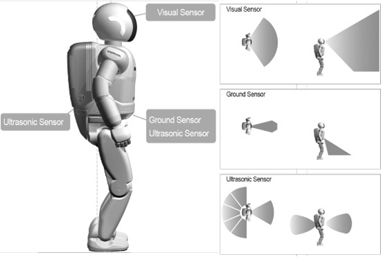
Figure 6.2 shows ASIMO’s visual sensors (cameras), ground sensors (laser and infrared), and ultrasonic sensors. The visual sensors can detect color and are used to recognize objects in the environment. The laser and infrared ground sensors are used to detect the floor and obstacles on the floor, and the ultrasonic sensors are also used to detect objects in the front and back. In addition, ASIMO has a number of other sensors such as touch sensors, gyroscopes, joint angle sensors, and more to measure the force and torque of its motors.
Figure 6.2
ASIMO visual, ground, and ultrasonic sensors.
© Honda, All Rights Reserved.
ASIMO has roughly 20 computers and micro-controllers on board to process the data received from all the sensors and make decisions. ASIMO carries its batteries in a backpack and can run for about an hour on a single charge.
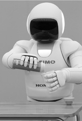
The latest model of ASIMO is 130 cm (51 inches) tall and weighs 48 kg (105 lbs.). Being a child-sized robot helps ASIMO to avoid being intrusive and to be more approachable by the people around it. This enables ASIMO to integrate well in its environment. The running speed of ASIMO is 9 km/hour (5.6 mph). ASIMO has a total of 57 degrees of freedom (DOF) in its body. A joint with one DOF can rotate along one plane, whereas a joint with, say, three DOF can rotate along three different planes. An example would be the human head, which can rotate forward and backward, left and right, and from side to side. ASIMO’s head, hand, arm, hip, and leg have three, seven, 13, two, and six DOF, respectively. Although having more DOF adds to the robot’s flexibility, it also increases the complexity of the control mechanism and algorithms. Figure 6.3 shows ASIMO using its hands to manipulate two objects. As you can see, having 13 DOF in each hand gives ASIMO enough flexibility to smoothly perform this task.
Figure 6.3
ASIMO manipulating two objects.
© Honda, All Rights Reserved.
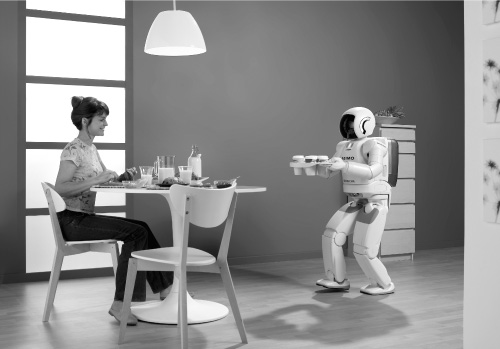
In the future, the biped walking ability of humanoid robots such as ASIMO will allow them to move freely in places that are designed for human use such as elevators, escalators, and stairs. With their dexterous hands, they will be able to manipulate objects that are designed for human use such as tools, utensils, and office products. This will naturally enable the humanoid robots to work and interact closely with people in their everyday normal life in places such as homes, offices, schools, and shopping malls. They will also be able to assist people in performing difficult or dangerous tasks such as firefighting or cleaning up hazardous toxic or nuclear waste. The human-like characteristics of humanoid robots helps them to be accepted and trusted by people to let them into their lives—for example, to be around their children, take care of the elderly, or perform housekeeping services. Figure 6.4 shows ASIMO serving a meal to a person.
Figure 6.4
ASIMO serving a meal to a person.
© Honda, All Rights Reserved.
To fully realize such capabilities, a lot more research and development in the areas of robotic software and hardware, mechanical engineering, and the like are required. The social, psychological, safety, legal, and other aspects of human interaction with humanoid robots must also be resolved. Imagine 50 years from now the world human soccer team playing against a team of humanoid robots to defend their championship!
AUTONOMOUS CARS
In July of 2002, the U.S. Defense Advanced Research Projects Agency (DARPA) announced the first competition for autonomous vehicles, called the DARPA Grand Challenge. The goal of this competition was to create a fully autonomous vehicle capable of completing a 150 mile (240 km) off-road course within a specified time. The prize money for this competition was $1 million.
The competition took place in March of 2004. Fifteen teams were qualified to participate in the final race. However, none of the teams were able to reach the finish line. The Red Team from Carnegie Mellon University, with its Sandstorm vehicle, traveled the farthest. Sandstorm traveled 7.4 miles (11.9 km)—less than 5 percent of the length of the course—before getting stuck on an embankment.
To successfully finish the race, each vehicle’s control software had to solve two problems simultaneously:
![]() Avoiding the obstacles on the road
Avoiding the obstacles on the road
![]() Following the correct path to the planned destination
Following the correct path to the planned destination
Some vehicles were very good at detecting and avoiding obstacles but had difficulty finding their way to the planned destination. Others were able to use the GPS to accurately find the path to the destination but were not able to detect the obstacles ahead.
DARPA repeated the Grand Challenge in October of 2005. This time, five teams completed the 132 mile (212 km) race. Stanley (see Figure 6.5), the vehicle from Stanford University’s Stanford Racing Team, crossed the finish line first and won the $2 million prize. Sandstorm (see Figure 6.6), the vehicle from Carnegie Mellon University’s Red Team, won second place, while H1ghlander, the vehicle from the Red Team Too—another team from Carnegie Mellon—won third place. The prizes for second and third place were $1 million and $500,000, respectively.
Figure 6.5
The Stanley autonomous vehicle.
© Stanford Racing Team, All Rights Reserved.
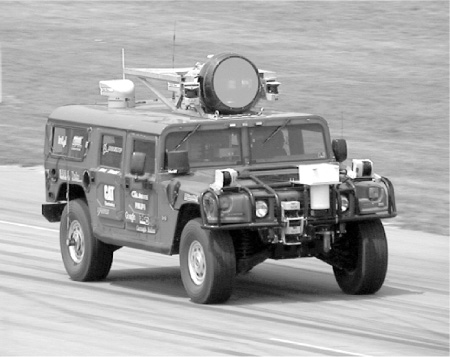
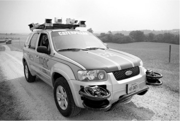
Figure 6.6
The Sandstorm autonomous vehicle.
© Red Team, All Rights Reserved.
The DARPA Urban Challenge was yet another autonomous vehicle competition. For this event, participating teams built autonomous vehicles capable of driving in traffic in an urban environment. The vehicles were required to autonomously perform complex maneuvers such as merging, passing, and parking while interacting with both manned and unmanned vehicle traffic. The DARPA Urban Challenge was held in November of 2007. Twenty teams proceeded to the final, and 11 teams were selected.
Tartan Racing, a collaborative effort by Carnegie Mellon University and General Motors Corporation, won the $2 million first-place prize with its vehicle, Boss (see Figure 6.7). The Stanford Racing Team, with its Junior vehicle (see Figure 6.8), won the $1 million second-place prize, and the team Victor Tango from Virginia Tech, with its Odin vehicle (see Figure 6.9), won the $500,000 third-place prize.
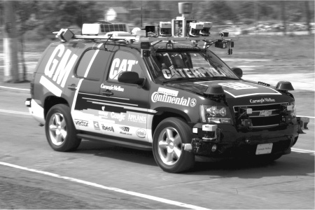
Figure 6.7
The Boss autonomous vehicle.
© Carnegie Mellon Tartan Racing, All Rights Reserved.
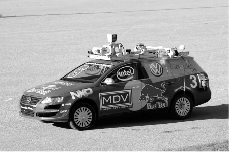
Figure 6.8
The Junior autonomous vehicle.
© Stanford Racing Team, All Rights Reserved.
Figure 6.9
The Odin autonomous vehicle.
© Victor Tango, All Rights Reserved.
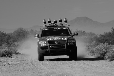
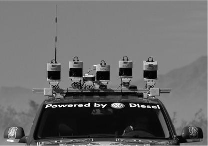
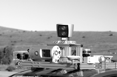
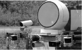
All vehicles used multiple sensors to collect large amounts of data from their surroundings. Laser scanners, or LIDARs (LIght Detection And Ranging), were the most commonly used sensor in these competitions. LIDARs calculate the distance to objects by measuring the time it takes for an emitted beam of laser light to travel to the object and back to the sensor. Based on the distance data, the robot builds a 3D view of the area in front of the vehicle. Many teams used several laser scanners to increase the amount of information from their surroundings. Some teams also used radar sensors, which emit radio waves and measure the time it takes for the wave reflection to return. Radars can see far in the distance through fog and dust. However, radar data is not as precise and accurate as LIDAR data. Some teams used radar as a secondary sensor in conjunction with LIDARs to detect objects in the far distance. The teams also used cameras to detect the edges, texture, and color of the road, and used GPS and odometry sensors to detect their position. Figure 6.10 shows some of the sensors that the teams installed on their vehicles.
Figure 6.10
Sensors on the teams’ autonomous vehicles.
© Stanford Racing Team, All Rights Reserved.
© Stanford Racing Team, All Rights Reserved.
© Carnegie Mellon Tartan Racing, All Rights Reserved.
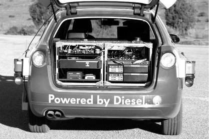
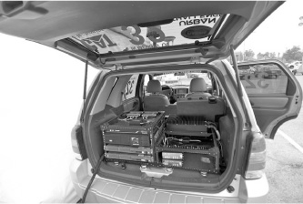
To process the input data from all sensors in real time, these vehicles required extensive computational power. Computers on the vehicles ran the algorithms that processed the sensors’ data to detect the position of the vehicle, the road, and the static and moving obstacles in the vehicles’ path, and based on this information planned where to move and what action to perform. Figure 6.11 and Figure 6.12 show the on-board computers used by Junior and Odin, respectively.
Figure 6.11
Computers on board the Junior autonomous vehicle.
© Stanford Racing Team, All Rights Reserved.
Figure 6.12
Computers on board the Odin autonomous vehicle.
© Victor Tango, All Rights Reserved.
Action commands selected by the computers were then sent to the vehicles to be executed. The vehicles used by the teams in the competition were augmented to be able to translate computer signals into the vehicle operating action. Such capability is usually referred to as a “drive-by-wire system.” The vehicles were able to receive commands such as “turn left” or “accelerate” from the computers and convert them to mechanical actions of turning the steering wheel to the left or pressing the gas pedal.
The DARPA Grand and Urban Challenges stimulated research for developing autonomous cars. Based on the result of these challenges, DARPA decided to pursue plans to utilize driverless cars on U.S. military bases in the future. After these events, many companies also started their own projects to develop autonomous cars. For example, Google started a project to advance this technology. Currently, its fleet of autonomous cars is being tested on the road.
Although there is no plan for autonomous cars to be commercially available anytime soon, there is a great deal of interest in advancing this technology, which will eventually lead to reliable driverless cars in the future.
AUTONOMOUS VACUUM CLEANERS
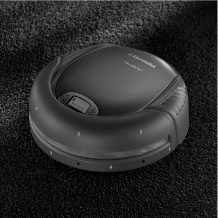
One of the goals of robotic technology has been to free people from doing mundane everyday tasks so they can engage in more creative and fulfilling activities. However, realizing this goal required extensive research to solve numerous problems, such as localization, navigation, and object manipulation. In addition, there were safety issues; for a long time, robots were only used away from people in the controlled industrial settings and research labs because it was not known whether robots could closely and safely interact with people. Indeed, it was only the early 2000s when commercially available robotic home products began to enter the market. In 2001, Electrolux introduced Trilobite, the first commercially available robotic vacuum cleaner (see Figure 6.13). A year later, iRobot introduced the Roomba robotic vacuum cleaner at an affordable price for home use (see Figure 6.14). These robots were able to autonomously move in the environment, vacuuming the floor, while avoiding walls and other obstacles. Later models, after finishing the vacuuming, were also able to find their charging station, return to it, and charge themselves to get ready for their next use. Later, other companies such as Neato Robotics (see Figure 6.15) and Evolution Robotics entered their own similar products into the market.
Figure 6.13
The Trilobite vacuum cleaner robot.
© Electrolux, All Rights Reserved.
Figure 6.14
The Roomba vacuum cleaner robot.
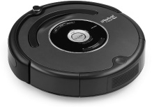
© iRobot, All Rights Reserved.
Figure 6.15
The Neato vacuum cleaner robot.
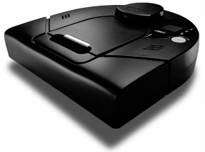
© Neato Robotics, All Rights Reserved.
Roomba has been among the most successful robotic vacuum cleaners on the market. So far, more 10 million units have been sold worldwide. Roomba is a round-shaped robot that is 13 inches (34 cm) in diameter and 3.5 inches (9 cm) tall. It uses a number of sensors for its operation. A large mechanical bump sensor in front of Roomba, shown in Figure 6.16, stops the robot when it comes in contact with obstacles such as walls or furniture and instructs the robot to change direction. Four infrared cliff sensors on the bottom front of the robot detect uneven surfaces and prevent the Roomba from falling down the stairs, as shown in Figure 6.17. An infrared transmitter-receiver couple wall sensor on the front right side of the robot keeps the robot at a constant distance from the wall as it moves along the walls. The black-and-white pattern on the caster wheel on the bottom of the robot is yet another sensor that shows whether the robot is moving or stuck, even if the wheels are turning. When the robot is moving, the alternating black-and-white pattern is detected by a light sensor in the caster wheel housing. If the robot is stuck, however, there will be no such changing pattern. Later Roomba models also have sensors to detect areas with more dirt as well as infrared sensors used for automatic docking to the charging station.
Figure 6.16
The horizontal brush and bump sensor.
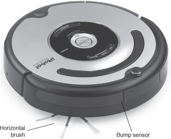
© iRobot, All Rights Reserved.
Figure 6.17
Roomba sensors and actuators.
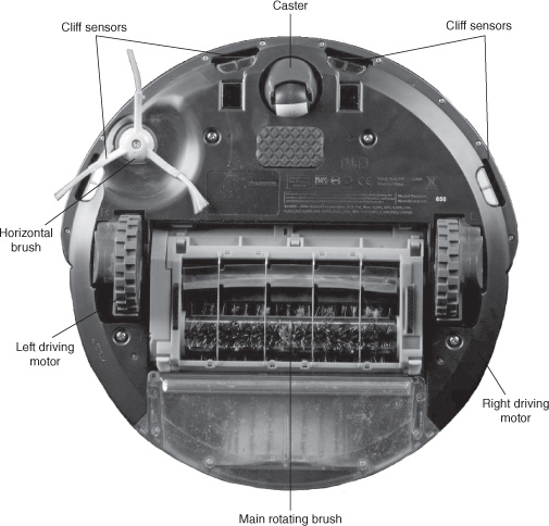
© iRobot, All Rights Reserved.
Based on the data from all sensors, the micro-controller installed inside the robot decides to continue sweeping the floor; turn around to avoid walls, furniture, or stairs; or go back to the charging station.
As shown in Figure 6.17, Roomba’s actuators include two independent electric motors installed on the bottom of the robot on its diameter to move the robot forward and turn it left and right (similar to how the BV-Bot worked). A horizontal brush on the right side of the robot is another actuator that sweeps debris away from the wall. The other actuators are the main rotating brush, the vacuum motor, and a buzzer.
When Roomba is turned on, it starts performing a preprogrammed spiraling motion to sweep the floor. However, once it detects an obstacle, it moves in a random direction while avoiding the obstacles (similar to the DB-Bot Stroll.bas program).
Unlike Roomba, which moves randomly in the environment, the Neato robot uses a laser range finder sensor and a simultaneous localization and mapping (SLAM) algorithm to map the entire room while it is vacuuming the room. Having a map of the room allows the Neato robot to travel in partially overlapped straight lines to vacuum the room, which can shorten the sweeping time. It also allows the Neato robot to detect and remember its current location in the room. Therefore, if its operation is interrupted, the Neato robot can later resume vacuuming from that location. Neato robot also has cliff sensors and can return to its home base for charging.
In addition to vacuuming, washing dishes and windows, doing the laundry, and ironing are examples of other home chores that robots will be able to do in the future. These tasks are more complex than vacuuming and therefore require the robots to have more advanced sensors and actuators and more intelligent software.
MARS ROVERS
Outer-space exploration is essential for advanced scientific research. However, manned space missions are very dangerous and costly. The outer-space conditions are extremely hostile to humans, and any manned mission needs to also plan for bringing back the astronauts, which adds to the complexity and the cost of the mission.
Intelligent robots reduce the complexity of such missions and are reasonable replacements for human astronauts. Rugged robots that can survive the harsh conditions of outer space, such as high levels of radiation and extreme temperature, can be built at a lower cost. They can carry the necessary sensors and equipment to capture and communicate scientific data to the control center on Earth. These space robots can also serve as a pre-cursor to manned missions.
In 1996, the U.S. National Aeronautics and Space Administration (NASA) sent a lightweight wheeled robotic rover named Sojourner to the planet Mars. It carried a series of scientific instruments to analyze the Martian atmosphere, climate, and geology. In 2003, NASA continued its exploration of Mars, sending two larger robotic rovers named Spirit and Opportunity. They worked for many years—well beyond their mission, which was expected to last for 90 days—exploring the Martian surface and geology, and sent back valuable information about Mars. In 2012, another robotic rover, called Curiosity, was sent to Mars. Its mission was to investigate the Martian geology and climate and to assess the planet’s habitability in preparation for future human exploration. Figure 6.18 shows the Spirit, Sojourner, and Curiosity rovers.
Figure 6.18
The Spirit, Sojourner, and Curiosity rovers (from left to right).
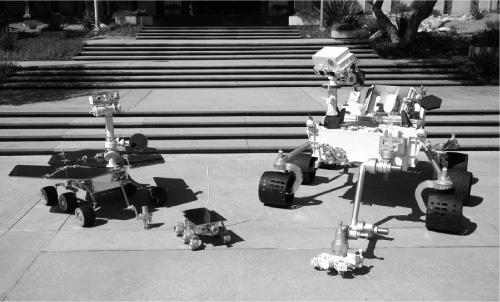
© NASA, All Rights Reserved.
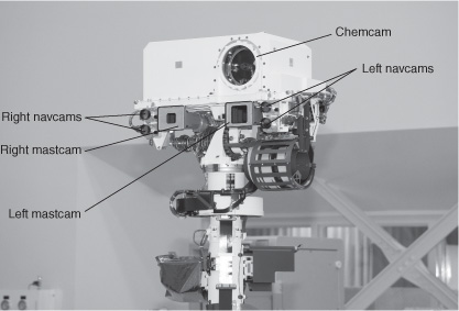
Curiosity, the largest rover that has been sent to Mars, has 17 “eyes.” Six cameras are responsible for the rover navigation and four cameras perform science investigations. Figure 6.19 shows the Curiosity rover’s mastcams, navcams, and chemcam.
Figure 6.19
Some of the Curiosity rover’s cameras.
© NASA, All Rights Reserved.
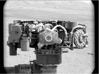
The chemcam analyzes the Martian rocks and soil by firing a laser at the planet’s surface to vaporize the area and studying the light and energy that is radiated from the resulting hot gas with the help of an on-board spectrograph. The chemcam can also use its laser to remove dust from the Martian surface and take detailed images. Figure 6.20 shows the chemcam in action and Figure 6.21 shows the APX spectrometer.
Figure 6.20
The chemcam in action.
© NASA, All Rights Reserved.
Figure 6.21
The APX spectrometer.
© NASA, All Rights Reserved.
In addition to the cameras and the spectrometers, Curiosity has a number of other sensors for radiation detection, environmental sensing, and atmospheric sensing.
Curiosity’s computer, or “brain,” is located inside the rover’s body. The computer can communicate with the rover’s science instruments, sensors, and actuators. The computer also controls the rover’s movements in addition to constantly checking the rover’s essential features such as its temperature, power generation, and storage throughout a Martian day to make sure the rover is in stable condition at all times. The computer is also responsible for communicating with the flight team on Earth and executing the team’s commands. For extra reliability, Curiosity has two computers, one of which is normally in the standby mode. If the first computer fails, the other computer can be instructed to wake up and take over control.
The Curiosity rover has a robotic arm that helps scientists to hold and maneuver the instruments close to the Martian surface. The arm has three joints—shoulder, elbow, and wrist—which allows the scientists’ instruments to be precisely positioned in the same way a human geologist would use the instruments. At the end of the arm is a dexterous actuator that can hold and operate different tools.
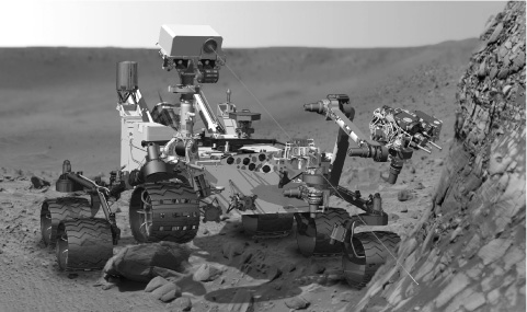
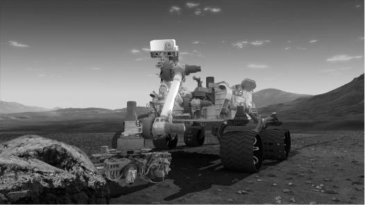
The Curiosity rover has six wheels, which are individually powered by the electric motors. Four additional steering motors on each of the two front and two rear wheels allow the rover to turn a full 360 degrees in place. The Curiosity rover can move at a top speed of 1.5 inches per second (about 4 cm per second) on flat, hard ground. Figure 6.22 shows the rover robotic arm and the driving wheels.
Figure 6.22
The Curiosity rover’s robotic arm and driving wheels.
© NASA, All Rights Reserved.
The Curiosity rover power source is a nuclear reactor that generates electricity from heat. This power source provides greater flexibility to the rover to use its scientific instruments, move, and communicate with Earth compared to the previous solar-powered rovers.
SUMMARY
In this chapter, you saw a few examples of state-of-the-art robotic systems that use a digital brain. The usage of strong computers and advanced sensors and actuators allows these powerful robots to solve difficult, real-world problems. These robots help people in performing difficult and dangerous tasks and allow them to enjoy more creative and fulfilling activities by freeing them from mundane tasks. In the future, robots will continue to improve the quality of life for human beings by expanding their difference-making services. People will use and interact with more robots in their everyday life. This will require that social, safety, psychological, legal, and other aspects of interactions between people and the robots be resolved.