
CHAPTER 7
EXTENDING DB-BOT
In Chapter 4, “Digital Brain,” and Chapter 5, “Programming the DB-Bot,” you built the DB-Bot, which was a simple programmable robot. It had a distance sensor and used two continuous-rotation RC servos to move in the environment. It also had a LED, which was controlled by a micro-controller. The Stroll.bas program enabled the DB-Bot to stroll in the environment while avoiding obstacles.
In this chapter, you will look at different ways of extending the software and hardware of DB-Bot. You will extend the Stroll.bas program to use the LED. You will also extend the DB-Bot hardware by adding a new light sensor and will look at a program that uses this sensor. At the end of this chapter, you will look at some limitations of the DB-Bot and explore ideas on how to extend DB-Bot to overcome these limitations both to perform new tasks and to do what it already does, but better.
The major topics covered in this chapter include the following:
![]() Extending the Stroll.bas program to turn on the LED when obstacles are detected
Extending the Stroll.bas program to turn on the LED when obstacles are detected
![]() Detailed build instructions for adding a light sensor to the DB-Bot
Detailed build instructions for adding a light sensor to the DB-Bot
![]() Exploring ideas on how to make DB-Bot smarter
Exploring ideas on how to make DB-Bot smarter
SIGNALING THE LED WHEN OBSTACLES ARE DETECTED
The Stroll.bas program, discussed in Chapter 4 and Chapter 5, used a distance sensor to detect obstacles in front of DB-Bot. Using this information, it commanded the robot to move forward or to turn right if it was too close to the obstacle. An improvement to this program would be to use the LED to signal to the user when the distance sensor detects an obstacle.
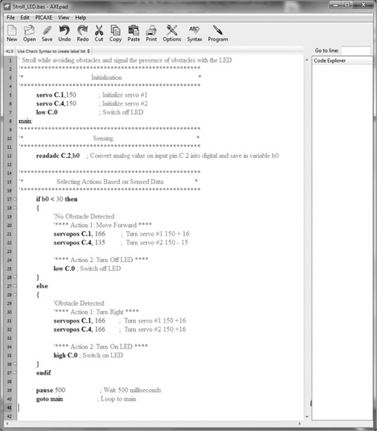
Figure 7.1 shows Stroll_LED.bas. It extends the Stroll.bas program by adding BASIC language LED control commands to turn the LED on or off, depending on the distance of the robot from an obstacle in front. When the value of the b0 variable on line 17 is less than 30, it means no obstacle is detected in front of the robot. In that case, the robot will execute the actions in lines 19–25. These include moving the robot forward (lines 21–22) and turning off the LED (line 25). If the value of b0 is 30 or larger, it means an obstacle has been detected in front of the robot that must be avoided. In that case, the robot will execute the actions in lines 29–35. These include turning the robot to the right (lines 31–32) and turning on the LED (line 35). Note that in the initialization section, the LED is turned off to make sure it is in a known state when the program starts running.
Figure 7.1
The Stroll_LED.bas program.
© 2014 Behnam Salemi, All Rights Reserved.
Observing the on and off states of the LED can be useful for the programmer during the development and testing of the program. Seeing that the LED turns on when an obstacle is detected and off when there is no obstacle shows that the distance sensor is working correctly. Also, if the robot turns to the right when the LED is on and moves forward when the LED is off, it indicates that the RC servos are working correctly.
Download the Stroll_LED.bas program into the micro-controller as described in Chapter 5. Before starting the download, make sure the three-pin header is in the PROG position. You will see that the robot will continue strolling in the environment while avoiding obstacles as before. However, this time the LED will also turn on when an obstacle is detected and turn off when the obstacle is avoided.
MAKING PROGRAMS MORE READABLE
Computer programming languages are designed to be accurate and efficient for computers and to be intuitive and easy-to-use for humans. As you may have already noticed, the BASIC computer programming language is not as intuitive for humans as spoken languages. This is generally the case for computer programming languages. For example, if you look at the command on line 17 of the Stroll_LED.bas program, if b0 < 30 then, it is not inherently obvious that it pertains to the distance of the robot from an obstacle. This is an example of a program lacking readability.
Readability is an important aspect of any program. It simply means how easy it is to understand what the program is doing. All modern programming languages offer tools to improve their readability. For example, most languages enable programmers to add comments to describe what the lines and sections of a program do. This helps programmers and users to understand how the program works. You have already seen examples of comments in the Stroll.bas and Stroll_LED.bas programs.
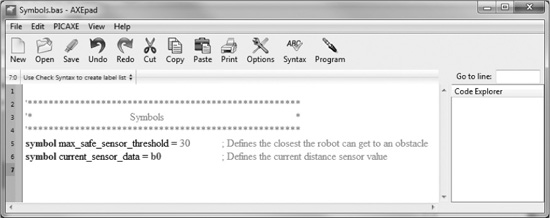
Another way to improve the readability of a program is to give meaningful names to the variables and constants in the program. For example, in the if command on line 17 of the Stroll_LED.bas program, the variable b0 and the number 30 do not specify what they are used for. However, if b0 were changed to current_sensor_data and the number 30 were changed to max_safe_sensor_threshold, for example, then it would be clear that they were being used in relation to the distance sensor. In BASIC, the symbol command allows you to assign names to constants and variables, as shown in Figure 7.2.
Figure 7.2
Assigning names to variables and constants.
© 2014 Behnam Salemi, All Rights Reserved.
On line 5 of Figure 7.2, the symbol command assigns the constant number 30 to the max_safe_sensor_threshold name. On line 6, the variable b0 is assigned the name current_sensor_data. Now these names can be used in the program instead of the original constants and variables to which they are assigned.
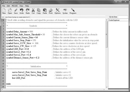
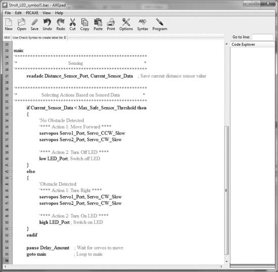
Figure 7.3 shows the “Symbols” and “Initialization” sections of the Stroll_LED_Symbol. bas program, and Figure 7.4 shows its main loop. Stroll_LED_Symbol.bas is the same program as Stroll_LED.bas except that in Stroll_LED_Symbol.bas, the constants and variables are replaced with more meaningful names via the symbol command.
Figure 7.3
Assigning names to the variables and constants in the Stroll_LED_Symbol.bas program.
© 2014 Behnam Salemi, All Rights Reserved.
Figure 7.4
The main loop of the Stroll_LED_Symbol.bas program.
© 2014 Behnam Salemi, All Rights Reserved.
The symbol commands are defined on lines 5–14. These assign names to all constants and variables used in the program. In the “Initialization” section, on lines 19–20, the constants 150, C.1, and C.4 are replaced by their equivalents, which were defined by the symbol command on lines 8, 12, and 13, respectively. Line 21 initializes the LED.
In the main loop of the Stroll_LED_Symbol.bas program shown in Figure 7.4, the symbols have also replaced the variables and constants values originally used in Stroll_LED.bas. As you can see, the lines of the program are now more descriptive, and the function of each line is easier to understand.
As computers improve in high performance, with faster processing power and larger amounts of memory, readability is becoming more desirable in program development. In general, programs that are more readable are preferable to programs that can run slightly faster and require a little less memory but are less readable. Readable programs are more easily understood by programmers and users, and are therefore more reliable and maintainable in the long run.
ADDING A LIGHT SENSOR TO DB-BOT
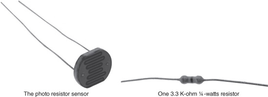
In this section, you will extend the DB-Bot hardware by adding a light sensor to it. The DB-Bot will use this new sensor, along with the distance sensor, to make decisions. The light sensor circuit consists of a resistor and a photo resistor. They will be connected to pin C.3 of the micro-controller, which is a digital input pin. You will add the light sensor to the DB-Bot by following these steps:
1. Detaching the prototyping board from the base
2. Installing the resistor
3. Installing the photo resistor
4. Reattaching the prototyping board to the base
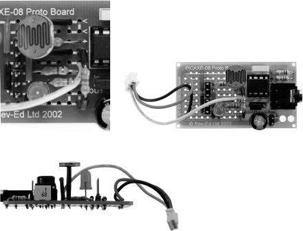
Figure 7.5 provides a complete inventory of the parts needed to extend the DB-Bot. You should be able to purchase these parts online. For detailed information about parts and a list of online vendors who carry them, see Appendix A, “Parts List.”
Figure 7.5
A complete inventory of the parts needed to extend the DB-Bot.
© 2014 Behnam Salemi, All Rights Reserved.
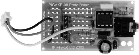
Detaching the Prototyping Board from the Base
During the assembly of the DB-Bot, you attached the prototyping board to the base using two strips of mounting tape. To begin installing the light sensor on the DBBot, detach the prototyping board from the base so that the back of the board is accessible for soldering the new components. To detach the board, follow these steps:
1. Disconnect the power, servo, and distance sensor connectors.
2. Pull the prototyping board away from the base using your fingertips or by wedging a small screwdriver between the board and the base. As always, follow the safety guidelines when working with tools.
3. Carefully remove the mounting tape from the back of the board. Then clean the back of the board with rubbing alcohol. (If the tape is still sticky, you may skip this step, keeping the tape on the board and reusing it to stick the board back onto the base. However, it might be a bit more challenging to solder the board while the mounting tape is still on.)
Installing the Resistor
Because there are other components already on the prototyping board, you must make sure the leads of the newly added components are isolated. Otherwise, they might connect to the rest of the components of the board and inadvertently create a short circuit. To prepare the resistor, follow these steps:
1. Remove the plastic covering of some hook wires, as shown in Figure 7.6. The coverings will be used to isolate the leads of the resistor.
Figure 7.6
Remove the plastic covering of some hook wires.

© 2014 Behnam Salemi, All Rights Reserved.
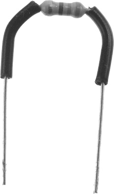
2. Cut two 1 cm pieces of the wire plastic covers and pass them through the resistor leads to isolate the leads, as shown in Figure 7.7.
Figure 7.7
Isolate the leads of the resistor.
© 2014 Behnam Salemi, All Rights Reserved.
3. Bend the leads of the resistor, as shown in Figure 7.8.
© 2014 Behnam Salemi, All Rights Reserved.
4. Connect the resistor between the ground (G) and the input pin C.3 of the micro-controller, as shown in Figure 7.9, and solder it to the board.
Figure 7.9
Connecting the resistor to the board.
© 2014 Behnam Salemi, All Rights Reserved.
Installing the Photo Resistor
A photo resistor is a resistor whose resistance changes depending on the amount of light it receives. This characteristic is used to detect the amount of light in the environment. To install the photo resistor, follow these steps:
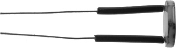
1. Cut two 1.5-cm pieces of the wire plastic covers and pass them through the photo resistor leads to isolate the leads, as shown in Figure 7.10.
Figure 7.10
Isolate the leads of the photo resistor.
© 2014 Behnam Salemi, All Rights Reserved.
2. Connect the photo resistor between the positive voltage (V) and the input pin C.3 of the micro-controller, as shown in Figure 7.11, and solder it to the board.
Figure 7.11
Connecting the photo resistor to the board.
© 2014 Behnam Salemi, All Rights Reserved.
Reattaching the Prototyping Board to the Base
If you kept the mounting tapes on the back of the board, you can use them to reattach the board to the base. Otherwise, cut two pieces of 1-inch mounting tape and attach them to the back of the board. Then peel off the mounting tape covers and attach the prototyping board to its original position.
PROGRAMMING THE LIGHT SENSOR
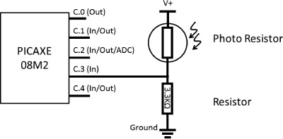
Figure 7.12 shows how the light sensor is connected to the micro-controller. The 3.3 K-ohm resistor connects input pin C.3 of the micro-controller to the ground voltage (G) and the photo resistor connects input pin C.3 to the positive voltage (V). In dim lighting conditions, the photo resistor will have a very high resistance compared to the 3.3 K-ohm resistor. As a result, the photo resistor will act as if it is an open circuit. This brings down the voltage level of input pin C.3 closer to the ground voltage through the 3.3 K-ohm resistor. Hence, the logic level of the input pin C.3 will be zero or low. When the light surrounding the photo resistor increases in brightness, the resistance of the photo resistor will drastically decrease, to an amount less than the 3.3 K-ohm resistor. Therefore, the voltage of input pin C.3 will be closer to the positive voltage (V), which is the logic level one or high.
Tip
In the current setup, the light sensor is connected to a digital input pin and therefore acts as a digital sensor, meaning it sets the logic level of input pin C.3 to either 0 or 1 depending on the amount of light in the surrounding area. Another possible approach for connecting the photo resistor to the micro-controller is to connect the photo resistor to an ADC input instead. This will enable the micro-controller to read a range of values depending on the intensity of the surrounding light and use them in its decision-making.
Figure 7.12
The schematic of the light sensor circuit.
© 2014 Behnam Salemi, All Rights Reserved.
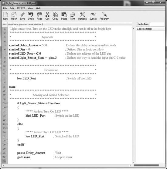
Figure 7.13 shows the Light_Sensor.bas program, which tests the light sensor’s functionality by turning on the LED when the surrounding light is dim and turning it off otherwise. This program also uses the symbol command for better readability. The symbols are defined on lines 5–8. On line 6, the name Dim is defined as the number 0 and on line 8, the command pinc.3, which reads the value of input pin C.3, is defined as Light_Sensor_State.
Figure 7.13
The light sensor test program.
© 2014 Behnam Salemi, All Rights Reserved.
Line 13 initializes the LED by turning it off and line 19 checks to see if the state of input pin C.3 (defined as Light_Sensor_State) is zero (Dim). If Light_Sensor_State is equal to Dim, then line 22 is executed, and the LED is turned on. Otherwise, line 27 will be executed, which turns off the LED. The program then goes to line 31 and, after a pause equal to Delay_Amount, executes the goto main command on line 32 and continues the loop.
THE NIGHT PATROL ROBOT
Combining the stroll behavior and the light-sensing capability gives DB-Bot the ability to perform night patrols. If, as the DB-Bot strolls in the environment, it detects that the light is dim, it can start flashing its LED. Also, if the DB-Bot’s LED is bright white, the DB-Bot can automatically turn on the LED when it detects a dim environment.
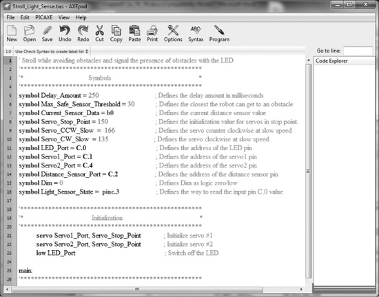
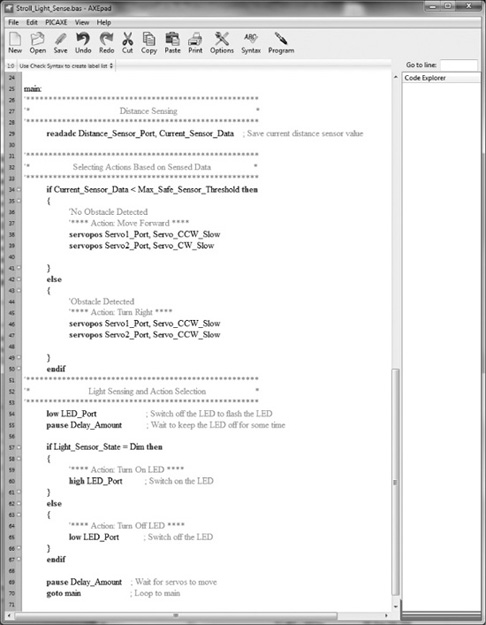
Figure 7.14 and Figure 7.15 show Stroll_Light_Sense.bas, which combines the Stroll.bas and the Light_Sensor.bas programs. Figure 7.14 shows the “Symbols” and “Initialization” sections and Figure 7.15 shows the main loop of the program. All sections of the code in Stroll_Light_Sense.bas were described earlier in the discussions of the Stroll.bas and Light_Sensor.bas programs. Lines 54–55 turn off the LED for Delay_Amount period of time during every iteration of the program right before the light-sensing section. This will cause the LED to show a flashing pattern. This flashing pattern works nicely with colored LEDs. If, however, a bright white LED is used and needs to remain on while the light is dim, lines 54–55 should be removed or commented out.
Figure 7.14
The “Symbols” and “Initialization” sections of the Stroll_Light_Sense.bas program.
© 2014 Behnam Salemi, All Rights Reserved.
Figure 7.15
The main loop of the Stroll_Light_Sense.bas program.
© 2014 Behnam Salemi, All Rights Reserved.
If a bright white LED is used, you need to make sure the light of the LED does not shine on the photo resistor. Otherwise, when the light is dim, the LED will be turned on and the light of the LED shines light on the light sensor and this will cause the micro-controller to turn off the LED and so on. This will create an unintended oscillatory pattern.
IDEAS TO MAKE THE DB-BOT SMARTER
A good way to think of ideas for making DB-Bot smarter is to look at what DB-Bot—or any robot and system, for that matter—does not or cannot do well and try to improve on that. After experimenting with DB-Bot, you might already have pinpointed some of its constraints or limitations. In this section, you will look at some of these constraints and different ideas to resolve them, which can improve the DB-Bot’s capabilities and makes it smarter.
In Chapter 5, you saw that when DB-Bot performed the stroll behavior, it always turned right to avoid obstacles in the environment. That’s how the Stroll.bas program was written. In some situations, turning right was the only correct decision. Sometimes, however, turning left or right would be equally valid decisions. Depending on the shape of the obstacle or the task at hand, there might be situations when turning left or right would not be equally valid; in those cases, the robot needs to make the correct decision to successfully complete the given task
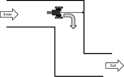
Figure 7.16 illustrates a scenario in which DB-Bot is tasked with strolling down a hallway. In that image, DB-Bot is at the first turn. The arrow in front of the robot shows the distance to the wall in front. At some point, DB-Bot gets too close to the wall and decides to avoid this obstacle. If DB-Bot were running the Stroll.bas program, then according to the program’s logic, DB-Bot would turn right to avoid the wall in front, as shown in Figure 7.16. In this case, this action happens to be the right decision. DBBot turns right and continues along the hallway.
Figure 7.16
Here, turning right is the correct maneuver for DB-Bot.
© 2014 Behnam Salemi, All Rights Reserved.
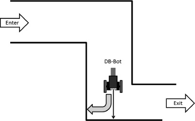
Figure 7.17 shows the DB-Bot in the hallway’s second turn, which is a left turn. The robot continues to go forward until it detects the wall in front. According to the Stroll.bas program, to avoid the wall, DB-Bot again turns right—but this time, this is the wrong decision. It guides the robot back toward the hallway entrance. Soon, it will wind up in an endless loop, as shown in Figure 7.18. The conclusion is that Stroll.bas cannot take the DB-Bot through a hallway with turns to the left.
Figure 7.17
Here, turning right is the incorrect decision.
© 2014 Behnam Salemi, All Rights Reserved.
Figure 7.18
The Stroll.bas program cannot take DB-Bot through a hallway with left turns.

© 2014 Behnam Salemi, All Rights Reserved.
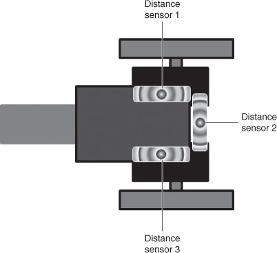
To resolve this problem, one approach is to add more distance sensors to DB-Bot. Figure 7.19 shows an extended version of the DB-Bot with three distance sensors.
Figure 7.19
The extended DB-Bot with three distance sensors.
© 2014 Behnam Salemi, All Rights Reserved.
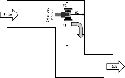
Figure 7.20 shows the extended DB-Bot in the position as in Figure 7.16, in the first turn of the hallway. In this situation, the extended DB-Bot checks the front distance sensor, sensor 2, to avoid obstacles as before. However, when an obstacle is detected in the front, instead of blindly turning to the right, DB-Bot checks the side distance sensors, sensors 1 and 3. It then turns in the direction with the farthest obstacle. So in this example, the robot will turn to the right, as the wall on the right is much farther away, causing distance sensor 3 to return a much smaller value.
Figure 7.20
The extended DB-Bot in the first turn of the hallway.
© 2014 Behnam Salemi, All Rights Reserved.
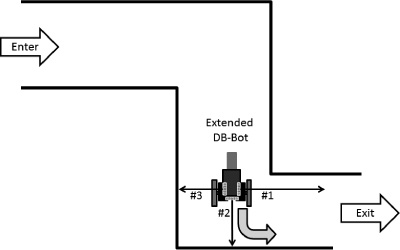
At the second turn, shown in Figure 7.21, the approach used at the first turn will again select the correct action. In this situation, when distance sensor 2 detects the front wall, the robot checks the side sensors (sensors 1 and 3). Because distance sensor 1 shows a smaller value, indicating a farther obstacle, the robot will turn left and successfully navigate the hallway.
Figure 7.21
Extended DB-Bot can successfully navigate the hallway.
© 2014 Behnam Salemi, All Rights Reserved.
Extending the robot’s hardware adds to the cost and complexity of the robot. For example, if you add two more distance sensors to the DB-Bot, not only do you need to purchase the sensors, you must also replace the micro-controller, as all the pins of the current 08M2 micro-controller are already being used. A bigger micro-controller, such as the PICAXE 14M2—which has more I/O pins—will be required. As a result, extending the robot’s software capabilities should also be considered. For example, you could solve the problem of navigating the hallway by extending the software such that anytime the DB-Bot detects an obstacle, it performs a 180-degree scan with a single distance sensor to decide which way to turn.
SUMMARY
In this chapter, you extended the software and hardware of DB-Bot. You modified the Stroll.bas program to turn on the LED when an obstacle is detected and turn it off otherwise. You also extended the DB-Bot hardware. You installed a light sensor on the DB-Bot and wrote software programs that used this sensor. Finally, you looked at some limitations of the DB-Bot and explored ideas on how to extend the DB-Bot software and hardware to overcome these limitations. In the next chapter, you will look at a number of advanced applications of the robotic technology.