
CHAPTER 1
THE RUNAWAY ROBOT, OR BUG-LIKE INTELLIGENCE
In this chapter, you will build a simple bug-like robot, called Bug Bot. What you will learn from Bug Bot is that a very simple mechanism can demonstrate some level of intelligence. As you will see, the source of intelligence in this robot is inherent in its mechanical structure. Bug Bot moves randomly in the environment, and its behavior is influenced by the characteristics of its environment such as the obstacles nearby, the slope of the surfaces surrounding the robot, friction, and so on.
The major topics covered in this chapter include the following:
![]() A review of the features and capabilities of Bug Bot
A review of the features and capabilities of Bug Bot
![]() Detailed building instructions for Bug Bot
Detailed building instructions for Bug Bot
INTRODUCING BUG-LIKE ROBOT (BUG BOT)
Bug Bot is a very simple robot that shows you how a simple mechanical system can demonstrate some level of intelligence. Bug Bot is a four-legged bug-like robot with antennae and a tail. Its pager motor generates a vibrating motion that bounces the robot in its environment. Bug Bot may move on a straight path and at some point may decide to turn left or right. Sometimes, when the robot hits an obstacle, it bounces back, turns around, and takes a new direction, as if it has a sense of purpose in its behavior!
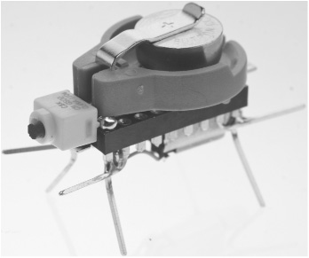
Figure 1.1 shows how Bug Bot will look when it is complete. The design of the robot is quite robust. It is easy to build, and should last a long time for your experiments. Its button cell battery is placed in a battery holder, making the battery easy to replace. A small switch turns the robot on and off.
Figure 1.1
How Bug Bot will look when it is complete.
© 2014 Behnam Salemi, All Rights Reserved.
BUILDING BUG BOT
You will create Bug Bot in five steps:
1. Preparing the antennae and legs on the base
2. Attaching the on/off switch to the base
3. Attaching the battery holder mounting tape
4. Attaching the battery holder and resistor
5. Attaching the motor and wiring
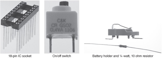
Figure 1.2 provides a complete inventory of the parts needed for building the Bug Bot.
Figure 1.2
The parts inventory list for Bug Bot.
© 2014 Behnam Salemi, All Rights Reserved.
You should be able to purchase these parts online. For detailed information about parts and a list of online vendors who carry them, see Appendix A, “Parts List.”
Preparing the Antennae and Legs on the Base
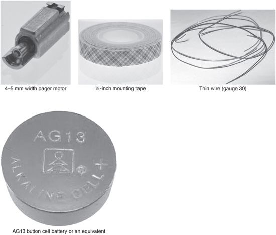
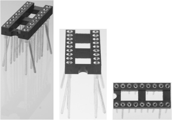
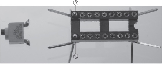
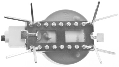
Begin the development of Bug Bot by preparing its legs and antennae. This involves bending and cutting the pins of the 18-pin IC socket that serves as the base for the project. Start by assigning a number to each pin so you can identify them later. Figure 1.3 shows the numbering you will use throughout the project. When the half circle cut is on the left side, the lower pins from left to right are pins 1 to 9 and the upper pins from right to left are pins 10 to 18. The side where the half circle cut is located will be the back of the Bug Bot.
Figure 1.3
The numbering of the 18-pin IC socket pins.
© 2014 Behnam Salemi, All Rights Reserved.
To prepare the antennae and legs, follow these steps:
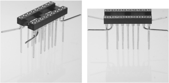
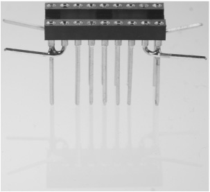
1. Bend pins 2, 8, 11 and 17 a few degrees to the sides, as shown in Figure 1.4. Then bend those pins toward the two ends of the robot such that they become parallel to the ground, as shown in Figure 1.5. Make sure that as you bend the pins, they go over their adjacent pins. For example, pin 2 should go over pin 1.
Note
Note that the pins are brittle. Applying too much pressure might break them. To get the best result, hold the tip of each pin with your fingertip or a nose plier to bend them. Do your best to bend the pins the same way such that the final shape is symmetric. They will serve as the robot’s antennae and tail.
Figure 1.4
Bend pins 2, 8, 11 and 17 a few degrees to the sides.
© 2014 Behnam Salemi, All Rights Reserved.
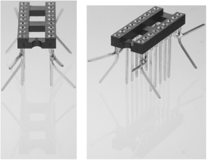
Figure 1.5
Bend pins 2, 8, 11 and 17 toward the two ends of the robot such that they become parallel to the ground toward the two ends of the base. The final shape is symmetrical.
© 2014 Behnam Salemi, All Rights Reserved.
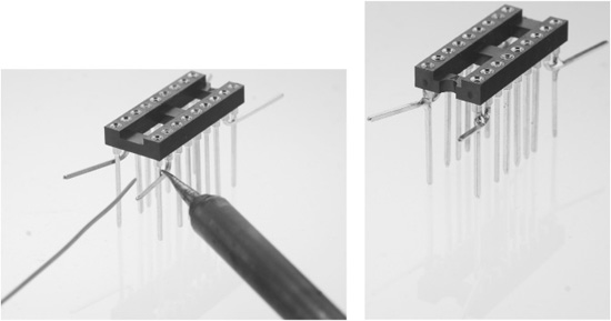
2. You may have noticed that the antennae and tail pins from the previous step can rotate. In this step, you will fix them in place. This will strengthen the antennae, tails, and the legs. Turn each of the pins fully toward their adjacent pins such that they touch each other. Then use a soldering iron to solder them together, as shown in Figure 1.6.
Figure 1.6
The antennae and tails are soldered to their adjacent pins.
© 2014 Behnam Salemi, All Rights Reserved.
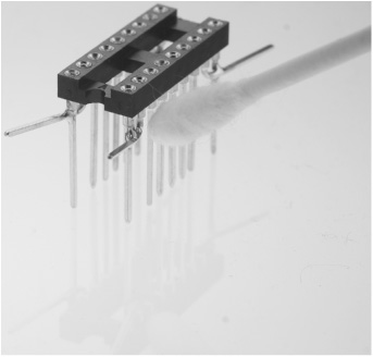
3. After soldering, clean the joints by using an alcohol-doused cotton swab to wipe the soldering flux from the joints, as shown in Figure 1.7. Figure 1.8 shows the base after soldering and cleaning. If you need to learn about soldering and required tools, do a search on the Internet for videos on “How to Solder” or “Introduction to Soldering.”
Figure 1.7
Use an alcohol-doused cotton swab to clean the soldered joints.
© 2014 Behnam Salemi, All Rights Reserved.
Figure 1.8
The base after soldering and cleaning.
© 2014 Behnam Salemi, All Rights Reserved.
4. Pins 1, 9, 10 and 18, which are the pins to which the antennae and tails are soldered, will be the legs of Bug Bot. Bend these pins 45 degrees toward the sides, as shown in Figure 1.9.
Figure 1.9
The legs are bent 45 degrees outward diagonally.
© 2014 Behnam Salemi, All Rights Reserved.
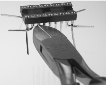
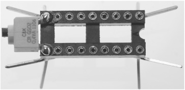
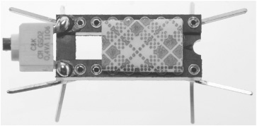
5. The rest of the pins are not needed and should be cut. Cut pins 3 to 7 on one side and pins 12 to 16 on the other side of the base with a wire cutter, as shown in Figure 1.10. For this step, make sure you follow safety guidelines and use a pair of safety glasses, as the cut pins may become airborne and can be very dangerous! Alternatively, you may cover the pins with a towel to prevent this. Figure 1.11 shows the base after the extra pins are cut.
Figure 1.10
Cut the rest of the pin. Be cautious; the cut pin may become airborne and could be dangerous. Use safety glasses.
© 2014 Behnam Salemi, All Rights Reserved.
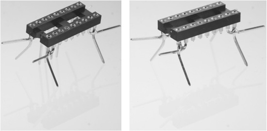
Figure 1.11
The base after the extra pins are cut.
© 2014 Behnam Salemi, All Rights Reserved.
Attaching the On/Off Switch to the Base
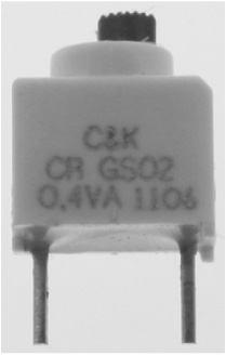
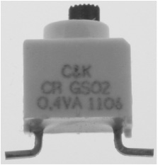
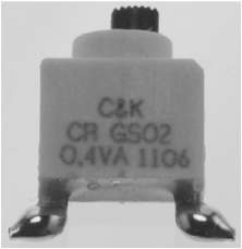
To be able to turn the Bug Bot on and off, you must add an on/off switch to the robot. Figure 1.12 shows the switch used in this project.
Figure 1.12
The on/off switch used in the robot.
© 2014 Behnam Salemi, All Rights Reserved.
To attach the on/off switch to the base, follow these steps:
1. Bend the leads of the switch using nose pliers or a similar tool. (See Figure 1.13.)
Figure 1.13
Bend the leads of the switch.
© 2014 Behnam Salemi, All Rights Reserved.
2. Use the soldering iron to put solder on the leads. (See Figure 1.14.)
Figure 1.14
Put solder on the leads.
© 2014 Behnam Salemi, All Rights Reserved.
3. Put solder on the top part of pins 9 and 10, which are the front legs of the robot, as shown in Figure 1.15.
Figure 1.15
Put solder on the top part of pins 9 and 10.
© 2014 Behnam Salemi, All Rights Reserved.
4. Solder the on/off switch to the robot base, as shown in Figure 1.16.
Figure 1.16
Attaching the on/off switch to the robot base.
© 2014 Behnam Salemi, All Rights Reserved.
Attaching the Battery Holder Mounting Tape
Cut ⅜ inch of the mounting tape. Peel off one side and stick the tape on top of the base, toward the back, as shown in Figure 1.17.
Figure 1.17
Stick the mounting tape on top of the base, toward the back.
© 2014 Behnam Salemi, All Rights Reserved.
Attaching the Battery Holder and Resistor
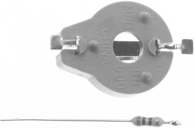
Bug Bot uses an AG13 button cell battery and a battery holder to—not surprisingly—hold the battery. Figure 1.18 shows the Bug Bot battery holder. Also, to slow down the speed of the Bug Bot pager motor, a series ¼-watt, 10 ohm resistor is used to limit the current drawn from the battery, as shown in Figure 1.19.
Figure 1.18
The Bug Bot’s battery holder.
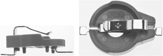
© 2014 Behnam Salemi, All Rights Reserved.
Figure 1.19
The 10 ohm resistor to slow down the Bug Bot’s pager motor.
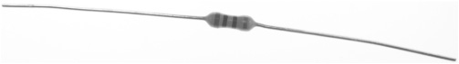
© 2014 Behnam Salemi, All Rights Reserved.
To attach the battery holder and resistor, follow these steps:
1. Cut one of the leads of the resistor to about ¼ inch (either side is fine), as shown in Figure 1.20.
Figure 1.20
Cut one of the leads of the resistor.
© 2014 Behnam Salemi, All Rights Reserved.
2. Put solder on the shortened lead and on the right side battery holder tab, as shown in Figure 1.21.
Figure 1.21
Put solder on the shortened lead and on the right side battery holder tab.
© 2014 Behnam Salemi, All Rights Reserved.
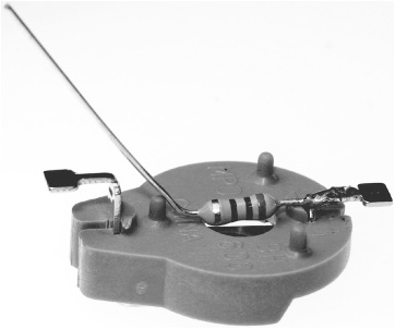
3. Solder them together, as shown in Figure 1.22. Make sure after soldering that the resistor is positioned at the center of the battery holder above the center hole, as shown in the figure.
Figure 1.22
Solder the resistor to the right side battery holder tab. The resistor should be positioned at the center of the battery holder above the center hole.
© 2014 Behnam Salemi, All Rights Reserved.
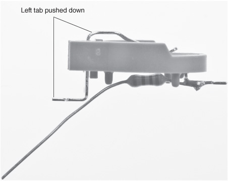
4. Push the battery holder tab on the left all the way down, as shown in Figure 1.23.
Figure 1.23
The left tab, pushed all the way down.
© 2014 Behnam Salemi, All Rights Reserved.
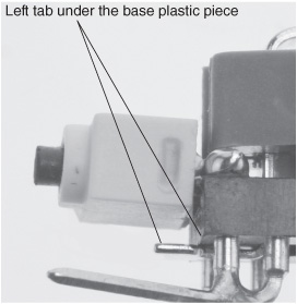
5. Peel off the other cover of the mounting tape that was installed in the previous steps and attach the battery-holder assembly to the base, as shown in Figure 1.24. The long resistor lead goes through the opening on the base plastic piece. The left tab, from the previous step, goes under the base plastic piece, as shown in Figure 1.25. You attach the battery-holder assembly to the base by pressing the battery-holder assembly to the mounting tape that was previously attached to the base, as shown in Figure 1.26. Next, cut the long resistor lead to about ¼ inch, as shown in Figure 1.27. Figure 1.28 shows what the Bug Bot looks like up to this point.
Figure 1.24
Attaching the battery-holder assembly to the base.
© 2014 Behnam Salemi, All Rights Reserved.
Figure 1.25
The left tab goes under the base plastic piece.
© 2014 Behnam Salemi, All Rights Reserved.
Figure 1.26
Attach the battery-holder assembly to the base by pressing the battery-holder assembly to the mounting tape.
© 2014 Behnam Salemi, All Rights Reserved.
Figure 1.27
Cut the long resistor lead to about ¼ inch.
© 2014 Behnam Salemi, All Rights Reserved.
Figure 1.28
What the Bug Bot looks like up to this point.
© 2014 Behnam Salemi, All Rights Reserved.
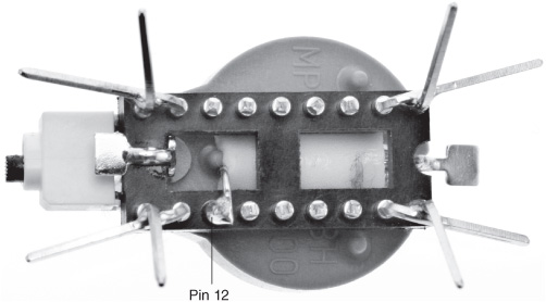
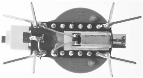
6. Figure 1.29 shows the bottom view of the Bug Bot. Use a nose plier to bend the resistor lead to a 90-degree angle toward pin 12 and solder them together, as shown in Figure 1.30. Pin 12 is one of the pins that were cut earlier.
Figure 1.29
The bottom view of Bug Bot.
© 2014 Behnam Salemi, All Rights Reserved.
Figure 1.30
Soldering the resistor lead to pin 12.
© 2014 Behnam Salemi, All Rights Reserved.
7. Solder the battery-holder tab under the on/off switch to pins 10 and 11. These pins were previously soldered together. For this step, you may use the resistor lead that was cut earlier as the connecting wire and trim the extra length after soldering, as shown in Figure 1.31. The resistor lead is metal, so when soldered, it quickly gets hot. Make sure you hold it with a plier or heat-resistant material.
Figure 1.31
Soldering battery holder tab to pins 10 and 11.
© 2014 Behnam Salemi, All Rights Reserved.
Attaching the Motor and Wiring
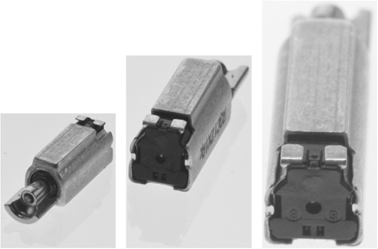
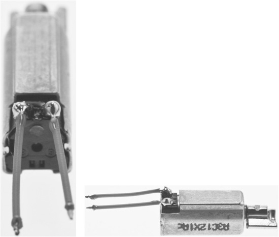
Bug Bot uses a pager motor to move. The pager motor generates a vibrating motion by a small electric motor that rotates an off-center weight attached to its drive shaft. Figure 1.32 shows the pager motor used in the project.
Figure 1.32
Different views of the pager motor used in the project.
© 2014 Behnam Salemi, All Rights Reserved.
To attach the motor and wiring, follow these steps:
1. Cut two ⅜-inch long thin wires (gauge 30) and remove about ![]() inch of the insulators on both ends. Solder the wires to the pager motor electric terminals, as shown in Figure 1.33. If your pager motor already comes with wires attached, you may skip this step.
inch of the insulators on both ends. Solder the wires to the pager motor electric terminals, as shown in Figure 1.33. If your pager motor already comes with wires attached, you may skip this step.
Figure 1.33
Two wires soldered to the pager motor electric terminals.
© 2014 Behnam Salemi, All Rights Reserved.
2. Cut ¼ inch of the mounting tape. Peel off one side and attach the tape under the base, as shown in Figure 1.34. Then, peel off the other side cover, as shown in Figure 1.35.
Figure 1.34
¼-inch mounting tape is attached under the base to hold the pager motor.
© 2014 Behnam Salemi, All Rights Reserved.
Figure 1.35
Peel off the mounting tape cover.
© 2014 Behnam Salemi, All Rights Reserved.
3. Attach the pager-motor assembly to the mounting tape, as shown in Figure 1.36. Make sure the pager motor off-centered weight can rotate freely and is not blocked by other parts of the base.
Figure 1.36
The pager-motor assembly is attached to the base.
© 2014 Behnam Salemi, All Rights Reserved.
4. Next, solder the motor wires to pins 8 and 12, as shown in Figure 1.37.
Figure 1.37
Solder the motor wires to pins 8 and 12.
© 2014 Behnam Salemi, All Rights Reserved.
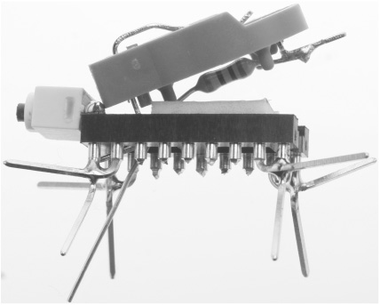
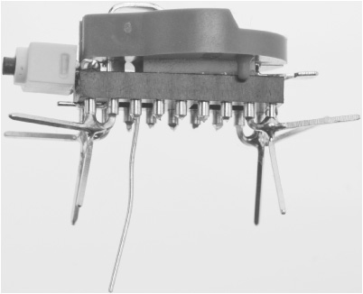
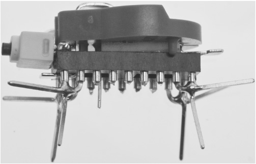
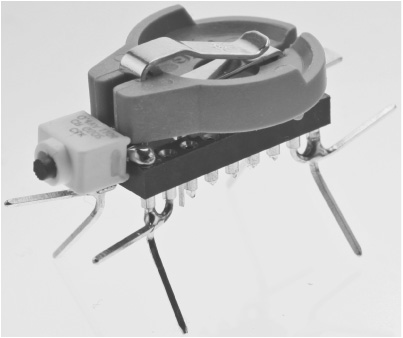
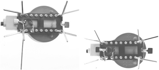
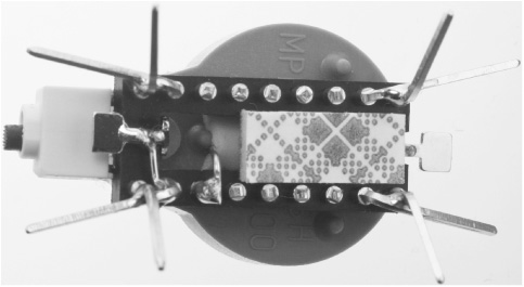
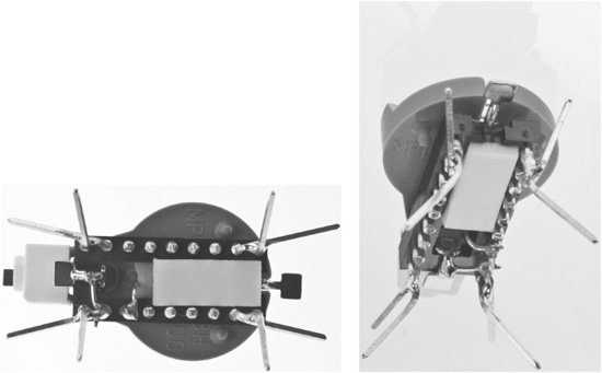
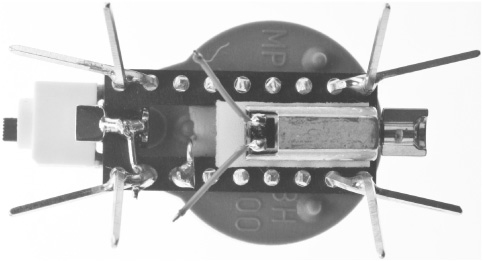
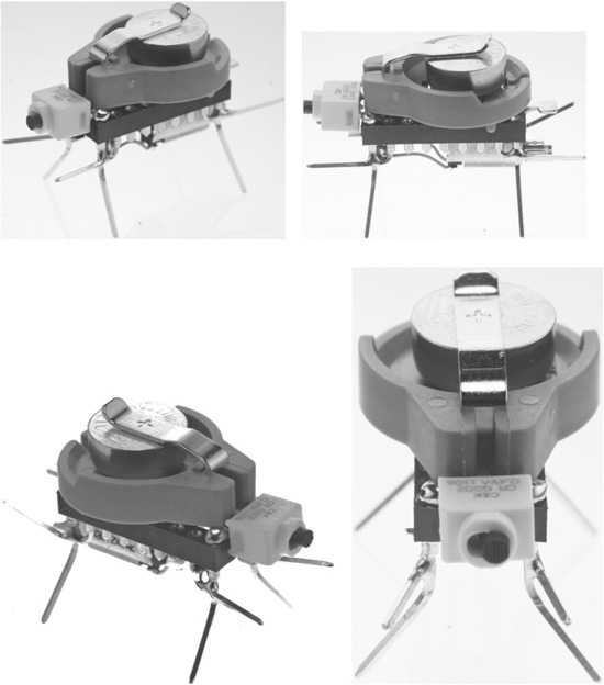
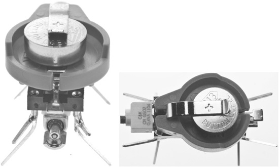
At this point, you have completed the Bug Bot assembly. Figure 1.38 shows different views of the completed Bug Bot with the battery installed.
Figure 1.38
Different views of Bug Bot with the battery installed.
© 2014 Behnam Salemi, All Rights Reserved.
SUMMARY
In this chapter, you learned that simple mechanical systems can show some simple forms of intelligence and built a Bug Bot to illustrate this concept. Bug Bot randomly moves in the environment and demonstrates a sense that its behaviors are purposeful, similar to a live creature.