
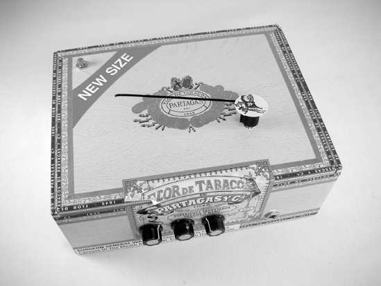
The Cigar-Box Synthesizer is an honest-to-God analog monosynth, not unlike the early synthesizers from Korg, Roland, and Robert Moog. Our simple little synthesizer is analog in that it abuses plain old integrated circuits into directly producing continuously variable musical notes and a monosynth because it makes one note at a time and thus can play melodies and bass lines but not chords. The Cigar-Box Synthesizer builds its thick tone by layering three octaves of each note and offers a musically useful range of about two-and-a-half octaves, with raw punky squeals above the high end and thunky mellow clicks below the low end. The resulting space-age theremin sound is harnessed with a dial-based pitch controller, which is much easier to master than the precise gestures of Leon Theremin and Clara Rockmore.
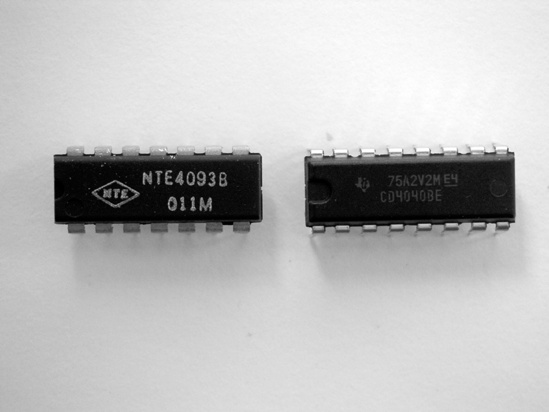
The Cigar-Box Synthesizer is based on misusing two over-the-counter integrated circuits: a CD4093 Quad NAND Schmitt Trigger and a CD4040 12-Bit Binary/Ripple Counter. We’re going to feed the first chip back on itself in order to make it function as an oscillator, producing a musically useful tone. If you’re unfamiliar with the term oscillator, think of a metronome, which produces a click at regular intervals (remember that old-timey metronome with the pyramidal wooden case and oscillating pendulum click-click-clicking on Grandma’s piano?). Run the metronome fast enough and your ear slurs those clicks together into a single burring tone. As the oscillator speeds up, the pitch of the tone increases.
The second chip functions as an octave divider; it will take the oscillator’s tone and give back the same pitch one octave (or several octaves) lower. Since the oscillator is binary, it’s actually producing a series of pulses, not a continuous tone. Slow them down and you hear them as discrete clicks. We feed that stream of pulses to the divider on its input, and at each output it generates one pulse for every two it receives, or one for every four, or one for every eight, and so on, thus producing ever-lower pitches exactly in tune with the input.
As with all ICs, references to the chips in this project assume you are looking at them from the top, with their dimples or half-circle notches to the left. In this position, the bottom left pin is number 1, the one to the immediate right is 2, then 3, all the way to the end of the row and wrapping around counterclockwise, as shown in Figure 17-2.
a standard soldering kit (See the appendix.)
an electric drill with 3/8″ and 1/2″ bits
Gorilla Glue
coarse-grit sandpaper and a sanding block
an amp, such as the Dirt-Cheap Amp built in Chapter 12