Start by making the barrel. Cut an 18″ length of CPVC.
Warning
Wear safety goggles or a face shield when cutting CPVC, because flecks of the material are sharp and can get in your eyes. The friction from your saw can also break down the polyvinyl chloride, releasing toxic fumes—flip to Chapter 11, the Electro-Didgeridoo, for more info on the dangers of heating PVC and its relatives.
Use your finger to clear away all the burrs and sharp edges from the ends, as these will ultimately tear up the marshmallows and annoy you.
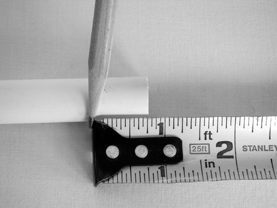
Measure 3/4″ from one end and mark it, as shown in Figure 24-4. This end of the barrel is the breech, where the explosion happens. The other end is the muzzle, where the marshmallow flies out.
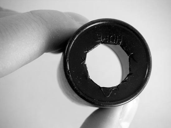
To make the chamber, use your utility knife to cut a roughly 1/2″ hole in the bottom of a film canister, as in Figure 24-5. These are devilishly hard to cut, so don’t beat yourself up if you make a mess of it; Gorilla Glue will conceal a multitude of sins.
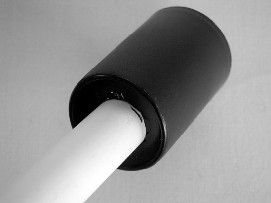
Slide the breech of the barrel into the hole, aligning the bottom of the canister with the line you drew in Step 3, so that the last 3/4″ of the breech is inside the film canister.
Smear the entire bottom of the canister’s exterior with glue. Slide the canister about 1/8″ up and down the barrel to spread the glue into the seam. As the Gorilla Glue cures, it will expand quite a bit, sealing the chamber.
Wipe up any excess glue, immobilize the barrel and chamber with a strip of duct tape, and set it aside to dry overnight. (Incidentally, once this is dry, it makes a pretty nifty mini-marshmallow blowgun. Give it a try.)
While the barrel and chamber are drying, you can start building the gun’s grip and firing mechanism. Start with the grip, which is easy. Use a miter box to guide you in cutting off the top of the grip at a 22.5-degree angle.
Whittle down the sharp edges of the grip (just to round it a bit, making it easier on the hand), and then sand these and the cut edges smooth, first with medium-grit sandpaper and finishing up with fine-grit. Sand any rough edges off the 5″ piece of trim while you’re at it.
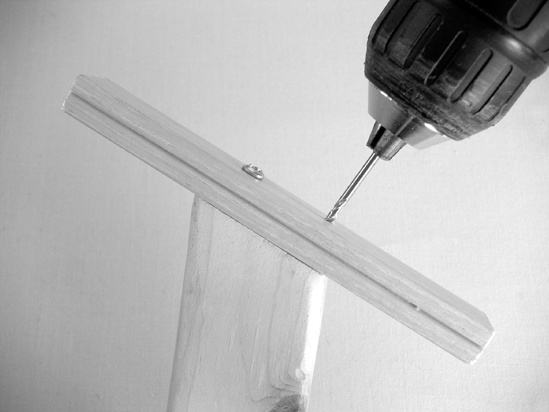
Center the handle on the piece of trim, drill a pair of guide holes through the trim and into the handle (as in Figure 24-6), and then screw the two together with the 1″ screws.
Now for the firing mechanism, which is definitely the trickiest part of this project. Put on your safety goggles; they might seem like overkill right now, but keep them on. Pull the cardboard packaging off the disposable camera. You’ll probably find a latch on the end of the camera, which easily opens the body. If not, take a flathead screwdriver to the camera body and pop it open.
Remove the battery (a standard AA).
Warning
Do not touch any of the contacts on the circuit board! This is very important!
Pull out the film and set it aside. (It’s still perfectly usable and can be loaded into any 35mm camera. Or you can use up all of the film before opening the camera, and then take it in for processing; you might lose the last couple pictures to light exposure, but most of the roll should print up fine.)
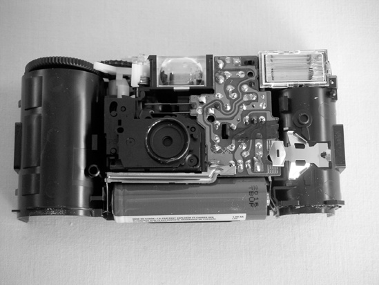
You should be able to access the circuit board (Figure 24-7). A disposable camera includes only one circuit, which is dedicated to running the flash unit. (The picture-taking portion of the camera is entirely mechanical.)
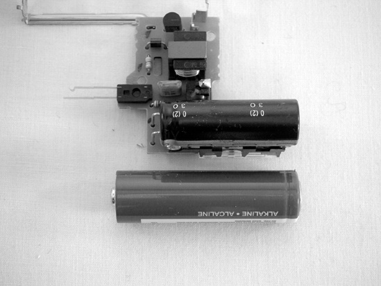
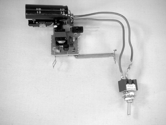
Figure 24-7. On the left is an open disposable camera. On this model, the big capacitor is tucked behind the flash (the flash is in the upper-right corner of the unit shown in the left picture). The right photo shows the back of the flash circuit; the AA battery gives a sense of how large that capacitor is—be careful! The two springy strips of copper on the left of the unit in the right photo (circled) form a rudimentary switch that triggers the flash. Remember this for later.
Warning
A camera flash relies on a large electrolytic capacitor, which can hold its charge for a long time. These capacitors are usually unmarked. Camera flash specs call for a capacitor around 470 μF—which is pretty hefty as is—but many of these look much larger to me, perhaps 1,000–3,000 μ. In any case, the camera uses a step-up transformer to charge this capacitor to upward of 300 volts. This wouldn’t necessarily be so bad by itself: a 470 μ capacitor charged to 300 volts holds 0.12 coulomb of electric charge, which isn’t life-threatening. A coulomb is equivalent to discharging 1 amp for 1 second,[18] and 1 amp is a hefty current (household wall current is 10–15 amps). Since it is difficult to predict how much resistance a finger will offer, we can’t know how quickly a clumsy brush of your thumb will discharge a large capacitor; it will take under a second, perhaps a tenth or hundredth of a second, which means that the 0.12 coulomb in the flash-unit capacitor might end up being 1.2, or even 12 amps. (If this is confusing, just remember this: With capacitors, faster discharge = higher current.)
Fortunately, the capacitor’s legs are so close together that it is unlikely this current will go through an important internal organ if you do get shocked—but it will hurt. A lot. If you scrape the capacitor’s leads with a screwdriver, it will let out a big fat spark that can blast little flecks of solder off the board (and into your eye; hence the required goggles).
On top of all of this, disposable camera flash circuits are cheap and a little unpredictable: Sometimes they ship charged, and even with the battery removed the capacitor will hold that charge. Always assume that a large capacitor is fully charged—even if you’re working with a device that’s factory new and that you’ve never powered up. Big capacitors are the handguns of electronics: Always assume they are loaded.
Start by making sure that capacitor won’t hurt you. If you have a multimeter, you can check how much voltage the capacitor is holding; otherwise, skip directly to bleeding the circuit in Step 17.
While your soldering iron is warming up, turn on your multimeter and set it to the thousands of DC volts range. Being sure to hold your probes by their insulated handles and careful not to touch anything but a single leg with each, touch one probe to either leg (or to the solder pad where each leg is connected to the circuit board—whichever is easiest to reach). A fully charged capacitor will read upward of 300 volts. (A negative sign means you’ve inadvertently reversed the probes—but it doesn’t matter: in this context, −300 volts is just as bad as 300 volts.) Anything larger than a few volts can give you a painful jolt. If the voltage is near zero, you can skip to Step 18—although I urge you to bleed the circuit (as described in the next step), just to be safe.
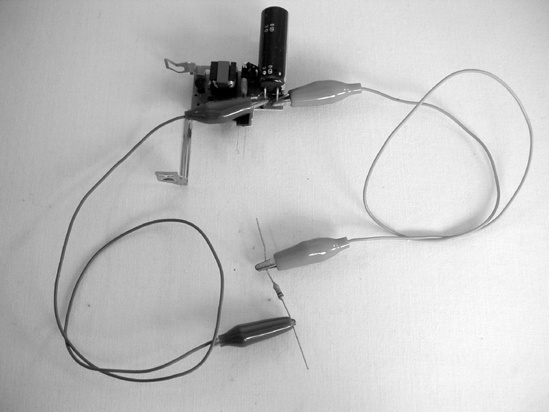
To bleed the capacitor, clip one end of each jumper to either leg of the 10k resistor. Then, taking pains to touch only the insulated part of the clips, connect each jumper to one leg of the capacitor, being very careful not to short the two legs of the capacitor or touch any other exposed metal (Figure 24-8). This will safely drain the capacitor in just a few seconds. (If you have a multimeter, check the capacitor again or even watch it drain.) You can then remove the clip jumpers.
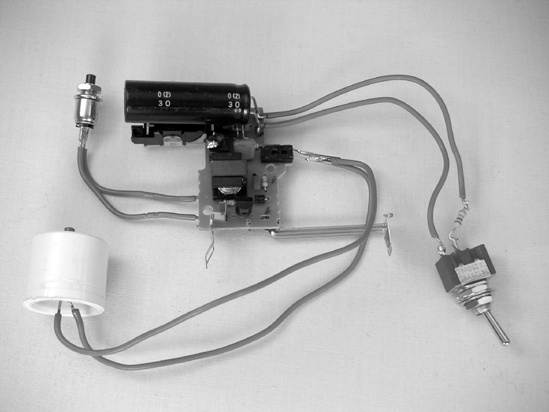
Now you can add a bleeder circuit to the flash (which will function as the gun’s safety—the finished circuit is shown in Figure 24-9). Start by making sure your SPST toggle switch is off (either using the continuity setting on your multimeter or by rigging up a little LED-resistor-battery-switch circuit, such as those featured in Chapter 2, the Switchbox).
After you are sure the switch is off, solder the 10k resistor to one terminal of the SPST toggle switch. Strip the ends of two 4″ or 5″ lengths of insulated wire (depending on the size of your enclosure), and solder one to the remaining switch terminal and the other to the open leg of the resistor. Then carefully solder the wires to each leg of the capacitor.
Test the bleeder circuit. If your multimeter has clip leads (probes that end in tiny alligator or hooked clips), clip one to each capacitor leg now, and you can monitor the capacitor’s charge-discharge cycle.
Replace the battery and charge the flash as normal; you’ll hear a high-pitched whine. After about 30 seconds, the indicator light will come on. (The multimeter will read upward of 250 volts when the light comes on; you’ll notice that even after the indicator lights up, the whine’s pitch continues to rise and the capacitor charges until it exceeds 300 volts.)
Trigger the flash and it will fire. Some flash models automatically begin recharging—you’ll hear the whine again. Otherwise, recharge the capacitor to its full 300 volts. Being careful not to touch any exposed wires, flick the bleeder switch; you’ll hear the whine drop in pitch, and the multimeter will fall to 50 volts or less. The trigger switch will not be able to make the flash fire. (Closing the trigger will likely drop the voltage back to zero, at which time some flash models will again try to recharge it. As long as the bleeder switch is closed, the capacitor won’t be able to go over 50 volts.)
After you know you can safely bleed the cap, keep the bleeder switch engaged, remove the battery, and then take out whatever screws are holding down the circuit board. (A tiny jeweler’s screwdriver is handy here, but an eyeglass screwdriver or the blade of a pocket knife will work, provided you don’t care about nicking up the blade.)
At this time, you might decide you want to add an AA battery holder and power switch (depending on how your camera is laid out). You’ll likely want to replace the charging button with a heartier SPST push button (again, depending on how your board is laid out). If you decide to do the latter, cut two 2″ pieces of insulated wire, strip the ends, solder one of each of the ends to each terminal of a push-button switch and the other ends to the copper pads corresponding to the charging switch.
You need to add a usable trigger (since the camera’s built-in trigger is usually just a pair of flexible copper tongues sticking off the edge of the board; see Figure 24-7) and build a trigger housing. Start by wiring the new trigger switch: cut two 6″ pieces of wire, strip the ends, and solder one wire to each of the two terminals of the push-button switch.
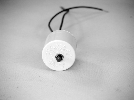
For the housing, take the 1/2″ CPVC cap and drill a small hole through the bottom. (A 3/16″ bit will create a tight fit for the RadioShack push-button switch, as shown in Figure 24-10.) Install the switch inside the cap, and then solder the two insulated wires to the two sides of the original trigger switch on the flash-unit circuit board; the camera flash with its new bleeder circuit, charging switch, and trigger is shown in Figure 24-11. (Because most enclosures will require threading the trigger wires through a hole, you might want to hold off on soldering the trigger connections until the end.) Reinstall the battery and test all of your new switches before moving on to the next step.
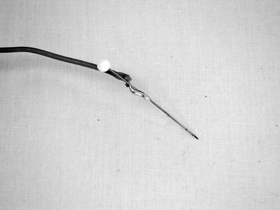
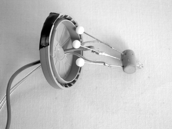
Now to build the spark plug. You’re basically re-creating the internal structure of the flashbulb in the open air so that the spark can ignite the propellant and fling the marshmallow toward heaven or foe. Start by building electrodes from the three pins: Cut three 9″ lengths of wire and strip both ends. Solder each wire to one pin, 5/8″ from the pin’s sharp tip (as shown in Figure 24-12).
Now pull the eraser off a new pencil, and drive one pin through the middle of the eraser’s side.
Insert the other pins about 1/4″ to either side, and at an angle. Slide the three back and forth until the spark gap between the tips of the middle pin and either side pin is less than 1/16″ (see Figure 24-13). This is your three-electrode spark plug, where the ignition spark will actually form.
Pop a hole in the middle of the film canister lid, and thread the wires through so that the spark plug is on the inside of the lid.
To connect the spark plug to the flash unit, remove the battery, engage the bleeder circuit, and use your multimeter to confirm that no voltage remains in the capacitor.
Carefully remove the camera’s flash bulb; notice which wire goes to the center of the reflector on the back of the bulb (the other two are interchangeable—see Figure 24-14).
Twist together the middle wire from the flash bulb and the lead to the middle pin in the spark plug, and wrap the connection with a little electrical tape. Do likewise with each of the two outer wires from the flash bulb and each of the two outer wires on the spark plug. (You’ll solder all of these later, after installing the firing unit in its enclosure.)
Test the sparker: Put on goggles, load the battery back into the camera flash, deactivate the bleeder, and charge the flash circuit. After it is fully charged, hit the trigger. You’ll see a very bright spark, accompanied by a loud crack! and possibly the smell of brimstone. If the spark doesn’t jump (and don’t be disappointed if it doesn’t; it’s normal to need to fine-tune the spark gap), check to make sure that
the battery is installed properly
the flash circuit whines as it’s charging
the capacitor is getting its full 300-plus volts
no bare wires are shorting the circuit.
If these are all okay and you still don’t get a spark, you should cut the power, bleed the capacitor, and carefully push the pins further into the eraser, getting the tips as close to each other as possible without touching.
Once you’ve gotten a few good sparks, set aside the firing unit and take out the wooden grip and the barrel (provided the glue is dry). Use the two hose clamps to bind together the grip, trigger, and barrel, as shown in Figure 24-15.
Decide how best to orient the firing unit’s plastic enclosure (probably just in front of the film-canister chamber is best, so it doesn’t obstruct access to the trigger). Drill holes in the enclosure’s lid for the charging button and bleeder switch. (I like to orient the switch so that when it’s pointed toward the end of the barrel, the firing circuit is live, and when it is pointed back, the safety is engaged.) If you’re using the RadioShack switches, then a 3/16″ or 1/4″ bit is about right for these holes.
Drill a hole for the power switch (if you added one) and the wires going to the spark plug (I suggest running the spark plug wires out of the back of the enclosure, as show in Figure 24-16, rather than the lid).
Drill a hole so you can see the “ready” LED on your flash unit (unless your enclosure has a handy window, as mine does).
Finally, drill guide holes through the bottom of the enclosure and into the piece of 1/2″ trim running along the top of the grip. Then attach the enclosure to the grip using two 1/2″ wood screws.
Detach the spark unit, thread its wires into the enclosure, solder them permanently to the old flash bulb wires, and wrap them in a little electrical tape, insulating them from each other and the rest of the circuit. Now is the time to look for any other potential short circuits as you mount the remaining switches and circuit board in the enclosure. (You can use double-sided tape or glue to secure the board.)
Slide the film canister lid up the wires so that it rests just behind the spark plug, and use a little piece of electrical tape to cover the hole (Figure 24-17).
Retest everything, adjusting the spark gap or other wiring as needed.
[18] As a formula, Q=C×V, where Q is the coulombs of charge, C is the capacitor’s value in farads, and V is the voltage it’s holding. Also note that Q=A×s—in other words a coulomb equals 1 amp times 1 second. This means that if the cap takes more than a second to discharge, the current is reduced, but the faster the discharge, the more the current is amplified. This fact is important to Taser and defibrillator manufacturers, as well as tinkerers messing with camera flashes.