My freedom will be so much the greater and more meaningful the more narrowly I limit my field of action and the more I surround myself with obstacles. Whatever diminishes constraint diminishes strength. The more constraints one imposes, the more one frees one’s self of the chains that shackle the spirit.
—Igor Stravinsky
Russian composer (1882–1971)
In the remainder of this book, I use metamodeling as the formalism to specify software languages: that is, one metamodel to specify the abstract syntax (see Chapter 6), one metamodel to specify (parts of) the concrete syntax (see Chapter 7), and in some cases, an extra metamodel to specify (parts of) the semantics (see Chapter 9). Because metamodeling is such an important technique, this chapter explains the underlying mathematical foundations of metamodeling. When you are familiar with metamodeling or if you are not interested in its precise definition, you can skip Section 5.1 and read only Section 5.2. Parts of this chapter were developed in cooperation with Arend Rensink (University of Twente, Netherlands).
To use metamodeling properly, we need to know the meaning of the words metamodel, model, invariant, and instance. In fact, we need to define a formalism in which to write metamodels. This section gives a mathematical foundation, based on graphs, for metamodels, models, and instances and explores the concept of model transformation in the context of this mathematical foundation. To summarize: A model is a type graph similar to a UML class diagram together with a number of constraints; an instance of a model is an indexed, labeled graph similar to a UML object diagram; an invariant is an extra constraint, such as an OCL invariant; and a metamodel is a model that is a part of a language specification and that specifies a certain aspect of a mogram, such as its concrete form, its abstract form, or its semantics. If you feel comfortable with these informal descriptions, you can skip this section, but if you really want to know what a model is, read on. (You can find even more detailed information and the precise mathematical definitions in Kleppe and Rensink [2008a, and 2008b].
Graphs are mathematical constructs that consist of a set of nodes (or vertices) and a set of edges between the nodes. Graphs have many variations. Here, two forms of directed graphs are used. In directed graphs, the edges have a direction; that is, every edge has a source and a target node.
The first type of directed graph that we need is a labeled, indexed graph, or simply a labeled graph. In a labeled graph, every node and every edge has a label, and every edge has an index number. Two different edges cannot have the same source, target, label, and index. These four characteristics uniquely identify an edge. The following is a rather informal definition of a labeled graph.
Definition 5-1 (Labeled Graph) A labeled graph is a combination of
• A set of nodes, which may include data values
• A set of edges
• A source function from edges to nodes, which gives the source node of an edge
• A target function from edges to nodes, which gives the target node of an edge
• A labeling function from nodes and edges to identifiers
• An indexing function from edges to positive natural numbers
To simplify the following explanation, we introduce the concept of the set of outgoing edges from a node with the same label.
Definition 5-2 (Outgoing edges) The set Out(n, l) is the set of edges that have node n as source and label l as label.
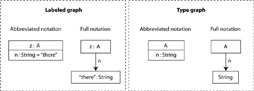
Figure 5-1 shows an example of a labeled graph in which the grayed-out text explains the various parts. Some comments on the notation are required. The figure contains symbolic identifiers. A symbolic id is not part of the underlying mathematical construct but is a convenience to indicate a certain part of the figure and can be used only within that figure. You will also find that most labels are preceded by a colon (:). The colon separates the label from the symbolic id in the case of nodes or from the index when it is a label of an edge. Furthermore, we have used the UML attribute notation as an abbreviation. Figure 5-2 shows what this abbreviation means. A node in a labeled graph can be a data value, in which case it may be shown before its label. Usually, its label will be the type of the data value.

The second type of graph that we use is a type graph with inheritance, or simply type graph. In this directed graph, all nodes represent types, and all edges represent relationship types. For instance, a type graph may contain the nodes {String, Integer, House, Person, Car} and the directed edges {<Person, String>, <House, Integer>, <Person, House>, <Car, Person>}, which represent, respectively, the name of a person, the number of a house, the house where a person is living, and the person owning a car. In this kind of graph, nodes can be related to each other by inheritance, meaning that some types may inherit from others. Following is a rather informal definition.
Definition 5-3 (Type Graph) A type graph is a combination of
• A set of nodes which may include data types
• A set of edges
• A source function from edges to nodes, which gives the source node of an edge
• A target function from edges to nodes, which gives the target node of an edge
• An inheritance relationship between nodes (a reflexive partial ordering)
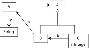
Figure 5-3 shows an example of a type graph. It looks very much like a UML class diagram and needs no further comments except that we use an abbreviation here as well (shown in Figure 5-2). Note that the names shown are the identities of the nodes and edges. We use them in the same way we use the data values in the labeled graph.
In our graph theoretical approach, a model is a type graph combined with a number of constraints. As we will see, constraints of several types can be part of a model. Thus, we use the following definition.
Definition 5-4 (Model) A model is a combination of a type graph and a set of constraints of various types.
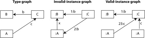
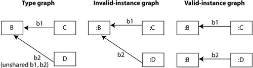
An instance of a model is a labeled graph in which every node and edge is of a type defined by the type graph. We say that an instance is typed over the type graph. The type of a node in the instance is a node in the model. More specifically, this means that the label of every node in the instance is equal to a node in the type graph. The type of an edge in the instance is an edge in the model. For edges, the typing is a bit more complex because we have to take the source and target nodes into account. An edge in an instance is properly typed only when its source and target are typed over the source and target of the edge’s type in the type graph. Figure 5-4 shows a type graph together with a valid and an invalid instance. Edge 2:b in this figure cannot be typed over the given type graph, because its target is not of node type B. Note that both the valid and invalid instances are correct labeled graphs.
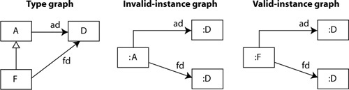
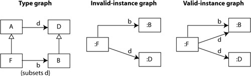
Inheritance is taken into account in the edge typings. Take, for instance, the situation in Figure 5-5. In this case, the type graph contains an edge, ad, from node A to node D, while node F inherits from node A. This means that an instance that has an edge from an F-typed node to a D-typed node is valid. The type of this edge is the edge ad in the type graph.
Instances of a model should not only be valid with regard to the type graph but also obey all the constraints in the model. This is expressed in the following definition.
Ten types of constraints have been identified. The first and best-known constraint type is an invariant, which is a logical expression over the type graph. But there are also a number of constraint types that are not invariants. These constraint types are well known from UML class diagrams, but this book takes a slightly different approach. The following subsections define each constraint type and explain how each type of constraint is satisfied by an instance.
Multiplicities regulate how many edges with the same source and the same label may be present in an instance. Multiplicities are defined in the type graph in the same form as in a class diagram: a..b, where a and b are positive numbers, and a is smaller than or equal to b. The upper-bound b may also be *, which means that the maximum number of edges is not constrained. An explicit multiplicity that is not present in the diagram is assumed to be 1..1. Figure 5-6 gives an example.

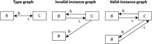
Bidirectionality constraints indicate that edges in an instance are always paired and are shown in the type graph by a line with two arrowheads, which is an abbreviation. In the type graph, two edges oppose each other: The source of the one is the target of the other. This is why the line has two labels. When an edge in the instance is typed over one of the edges in the type graph, there should also be an edge typed over the opposing type edge. Figure 5-7 shows an example.
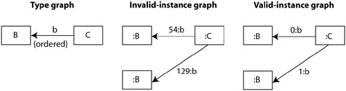
Ordering constraints specify that the index numbers of all edges from an outgoing set of edges (see Definition 5-2) are subsequent numbers starting with 0. Ordering is shown by the text {ordered} next to an edge in the type graph. Figure 5-8 shows an example.
A labeled graph may not have two edges with the same source, target, label, and index. A uniqueness constraint indicates such a case, disregarding the index. A uniqueness constraint is denoted with the text {unique} next to an edge in the type graph. Figure 5-9 shows an example.

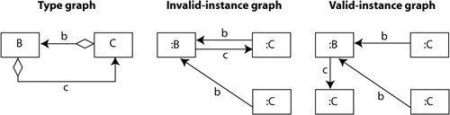
The acyclic constraint is defined on a number of edges in the type graph. Each edge in this set is marked with an open diamond shape at the source end. An instance is valid according to the acyclic constraint if its subgraph, consisting of edges typed over the edges in the acyclic constraint, is an acyclic graph. In an acyclic graph, you cannot get back to the same node by traversing edges. Figure 5-10 gives an example.
Like the acyclic constraint, the unshared constraint is defined on a set of edges in the type graph. The acyclic constraint is shown by the text {unshared ...}, with the names of the edges in the set on the dots. This constraint specifies that all edges in the instance that are typed over edges in the unshared constraint must have a different target. Figure 5-11 shows an example.
The last three constraint types all deal with specialization/generalization. The redefines constraint is applied to two edges where the one edge is defined between nodes that are the supertypes of the source and target nodes of the other edge. This constraint indicates that the first type edge is hidden by the second. The first type edge may not be used as the type of an edge in an instance when that edge has the subnode as source. Figure 5-12 shows an example.

The subset constraint is applied to two edges where the one edge (d) is defined between nodes that are the supertypes of the source and target nodes of the other edge (b). Thus, the set of outgoing edges of every node of the subtype must contain a d-typed edge for every b-typed edge. Figure 5-13 shows an example.
The union constraint is the reverse of the subset constraint but involves more than two edges in the type graph. Figure 5-14 gives an example.

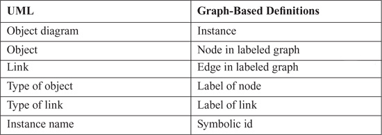
The remainder of this book uses the familiar notation of UML class and object diagrams to represent models and instances as defined in this section. Table 5-1 shows the mapping we use for class diagrams, which may optionally be combined with OCL invariants, and Table 5-2 shows the mapping for object diagrams.
Table 5-1. Mapping of UML Class Diagram Concepts to Graphs
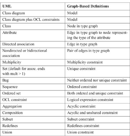
Table 5-2. Mapping of UML Object Diagram Concepts to Graphs
Now that it is clear what model and instance mean, it is time to focus on the concept of metamodel, which is usually defined as a model of a model. But this view is too simplistic. What is meant is that where a model defines a system, a metamodel defines a mogram. (For modeling languages, each mogram is a model; that is where the model-of-model idea comes from.) The relationship between model and system is an instance-of relationship, just like the relationship between metamodel and mogram.
However, Section 4.1.2 introduced two models that are part of a language specification: the concrete syntax model and the abstract syntax model. In Section 9.3.1, you will see that we can also build a model of the semantic domain. Which of these is the metamodel? Usually, a metamodel is a model of the abstract syntax of a language. But I define the term in a broader sense. My definition is the following.
In my view, any model that is part of a language specification can be regarded as a metamodel. Therefore, I do not use the term metamodel often. Instead, I speak of abstract syntax model, concrete syntax model, and semantic domain model, all of which are models used to specify a language and are therefore metamodels. The term metaclass indicates a class in a metamodel, which according to our definitions is a node in the type graph of the model.
Section 5.1.2 explained the relationship between a model and the instances of that model, a relationship based on constraining the set of all labeled graphs to those that are valid according to the model. For a metamodel, the same relationship between model and instances holds: The metamodel restricts the set of possible mograms to a set of valid mograms. Not any combination of letters that I write is a valid English sentence; it is the constraints that specify which ones are and which are not. Thus, a concrete syntax model restricts the number of valid mograms to the ones that have a valid concrete representation. An abstract syntax model restricts the number of valid mograms to the ones that have valid abstract forms. A semantic domain model determines what is and what is not a valid semantic domain.
This section explains how the way languages are specified relates to the concepts identified in model-driven approaches to software development.
As defined by the Object Management Group (OMG), model-driven architecture has always regarded the notion of platform as central. There are platform-independent models and platform-specific models. However, people who do model-driven development in practice do not use these terms, because they are rather useless. Nevertheless, I owe you an explanation of what a platform is with regard to languages and language specifications.
Fortunately, Atkinson and Kühne [2005] have provided a useful notion of platform. In the following definition, I use my own words to describe this concept.
Definition 5-7 (Platform) A platform is the combination of a language specification, predefined types, predefined instances, and patterns, which are the additional concepts and rules needed to use the capabilities of the other three elements.
Using Atkinson’s definition, each mogram is bound to a certain platform. The mogram is completely specific to the language it is written in and to the types, instances, and patterns associated with that language. In the same manner, the mogram is more or less independent of any other platform—language—insofar as this language differs from the original one.
Although at the first glance it looks as though this definition of platform completely destroys the way the OMG looks at things, it is in fact very compatible. According to the OMG, “the term platform is used to refer to technological and engineering details that are irrelevant to the fundamental functionality of a software component” [OMG-MDA 2001, p. 5]. Note the use of the word fundamental. The platform is relevant for the functionality of the software component but not fundamentally. To a language user, the language specification, predefined types, predefined instances, and patterns—the platform—are indeed technological and engineering details that are necessary for the implementation of the software but are not fundamental to it. The language is a means, not a goal. Another language with other predefined elements might do just as well. (A similar difference is made in Brooks [1995]: essential and accidental parts of software construction. There is more on this in Section 8.1.)
The only concept that Atkinson and Kühne discard is the notion of platform-independent model. No model is platform independent, because all models/mograms need to be expressed in some sort of language. Instead, the only thing we can say is that some models are expressed in a language/platform that has a higher level of abstraction than others. In fact, we can compare a platform to the virtual zero line from Section 3.2. Everything below the platform is hidden from view to the users of the platform.
Another concept central to model-driven approaches is model transformation, or the translation of one model written in one language into another model that is usually written in another language.
What are model transformations in a context of models and instances being graphs? The obvious answer would be that model transformations are graph transformations, but this is not completely true. Graph transformations can be defined on any graph, and a model is not just any graph.
To understand model transformations, you must first realize that the meaning of the word model in this context is mogram. Model transformations transform mograms but are defined over the mogram’s ASM. Thus, I consider a model transformation to be a function from one ASM to another that works on instances of these ASMs. This is similar to the function plus(Integer, Integer): Integer, which is defined on the type Integer and executed on individual instances, as in plus(2, 53).
The situation for model transformations is a bit more complex, because a model transformation may have both multiple inputs and/or multiple outputs. Therefore, the complete definition is the following.
A taxonomy of transformations based on the elements in a language specification is presented in Kleppe [2006]. Figure 5-15 provides an overview of the relation between kinds of transformations and elements of a language specification. The figure shows the concrete syntax model (C1) and abstract syntax model (A1) of one language (L1) in the upper part and the concrete syntax model (C2) and abstract syntax model (A2) of another language (L2) in the lower part, as well as the various types of transformations that can exist among these four elements.
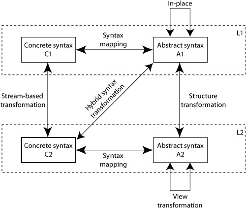
To understand the figure correctly, you must realize that some transformations are defined to transform a mogram in one language into a mogram in another language (the stream-based, hybrid syntax, and structure transformations), and some are defined to change a single mogram written in one language (the in-place and view transformation). The figure also includes the language’s syntax mapping as a transformation. Another possibility, not shown in this figure, is a structure transformation defined to transform a mogram to another mogram written in the same language.
Note that although the arrows in the figure indicate a bidirectionality, not all transformations need to be defined bidirectional. The arrows indicate that transformations in both directions are possible. The following transformation types are recognized.
• In-place transformations are transformations that change the source mogram. Formally, an in-place transformation is a mapping from the abstract syntax model Ai of language Li to the same abstract syntax model Ai. Refactorings are in-place transformations.
• View transformations, like in-place transformations, are mappings from abstract syntax model Ai of language Li to the same abstract syntax model Ai, but they serve a different purpose. Views present the same system from a different viewpoint, using different criteria. Views are always dependent on their source mogram. If the source mogram changes, the view should change. If the source mogram is removed, the view should be removed. We therefore consider the view to be part of the original source mogram.
• Stream-based transformations are mappings from a concrete syntax model of one language to the concrete syntax model of another. This is very well known in practice: namely, the change of a textual representation of a mogram into another textual format. The name indicates that these transformations are focused on textual, one-dimensional languages, which are handled sequentially, that is, one token after another. Examples of this type of transformation are templates written in such languages as AWK, but some XSLT programs also fall into this category.
• Structure transformations are mappings from an abstract syntax model to an abstract syntax model. These abstract syntax models may be the same or may be different. This means that a structure transformation may transform a mogram of one language into a mogram of either the same language or another language. In-place and structure transformations differ, even when the language source and target mograms have the same language. An in-place transformation makes changes in a single mogram; the input and output mograms are the same item. A structure transformation produces a new mogram; the source and target mograms are two separate items. This might seem a minor difference from a theoretical viewpoint, but from the point of tool interoperability, it is important. In essence, the latest version of the Query/View/Transformation (QVT) standard [OMG-QVT 2007] focuses on structure transformations, although, as its name suggests, it should also provide a solution for defining views.
• Hybrid syntax transformations take an abstract from of a mogram in one language as source and produce text, that is concrete syntax, in another language as output. Examples are transformations implemented in Velocity [Velocity 2008] or JET [JET 2008] templates. In this case, the source mogram is available in the form of an abstract syntax graph, but the output is a character stream. These transformations map the abstract syntax of one language on the concrete syntax of another.
Metamodeling is the formalism for specifying languages; therefore, we need to be clear about what a model and a metamodel are. For this, we use the mathematical construct known as a graph, which is a set of nodes and a set of edges that go from one node to another.
A model is a type graph with a set of constraints. Models are depicted as UML class diagrams with OCL constraints. An instance of a model is also a graph. This instance graph has labels on its nodes and edges, as well as indexes on its edges. An instance is a valid instance only when all the constraints are met.
A metamodel is a model that is used to define a language. A language specification will have an abstract syntax model (ASM), a concrete syntax model (CSM), and a semantic domain model (SDM), each of which is a model used to define a language and therefore is a metamodel. Mograms are instances of the abstract syntax model.
In our terminology, model transformations are mogram transformations, transforming one mogram into another. Model transformations are defined on the metamodels that deal with syntax (structure) and can be considered to be mathematical functions. There are several types of transformations:
• Structure transformations: from the ASM of the source language to the ASM of another language
• Syntax transformations: from the ASM of a language to the CSM of the same language
• Hybrid syntax transformations: from the ASM of a language to the CSM of another language
• In-place transformations: from the ASM of a language to the ASM of the same language, changing the same mogram
• View transformations: from the ASM of a language to the ASM of the same language, creating a different, dependent mogram
• Stream-based transformations: from the CSM of a language to the CSM of another language